Capacitor
.jpg) | |
| Type | Passive |
|---|---|
| Invented | Ewald Georg von Kleist |
| Electronic symbol | |
 | |
A capacitor is a passive two-terminal electrical component that stores electrical energy in an electric field.[1] The effect of a capacitor is known as capacitance. While capacitance exists between any two electrical conductors of a circuit in sufficiently close proximity, a capacitor is specifically designed to provide and enhance this effect for a variety of practical applications by consideration of size, shape, and positioning of closely spaced conductors, and the intervening dielectric material. A capacitor was therefor historically first known as an electric condenser.[2]
The physical form and construction of practical capacitors vary widely and many capacitor types are in common use. Most capacitors contain at least two electrical conductors often in the form of metallic plates or surfaces separated by a dielectric medium. The conductors may be foils, thin films, or sintered beads of metal or conductive electrolyte. The nonconducting dielectric acts to increase the capacitor's charge capacity. Materials commonly used as dielectrics include glass, ceramic, plastic film, paper, mica, and oxide layers. Capacitors are widely used as parts of electrical circuits in many common electrical devices. Unlike a resistor, an ideal capacitor does not dissipate energy.
When two conductors experience a potential difference, for example, when a capacitor is attached across a battery, an electric field develops across the dielectric, causing a net positive charge to collect on one plate and net negative charge to collect on the other plate. No current actually flows through the dielectric, instead, the effect is a displacement of charges through the source circuit. If the condition is maintained sufficiently long, this displacement current through the battery seizes. However, if a time-varying voltage is applied across the leads of the capacitor, the source experiences an ongoing current due to the charging and discharging cycles of the capacitor.
Capacitance is defined as the ratio of the electric charge Q on each conductor to the potential difference V between them. The unit of capacitance in the International System of Units (SI) is the farad (F), which is equal to one coulomb per volt (1 C/V). Capacitance values of typical capacitors for use in general electronics range from about 1 pF (10−12 F) to about 1 mF (10−3 F).
The capacitance of a capacitor is proportional to the surface area of the plates (conductors) and inversely related to the gap between them. In practice, the dielectric between the plates passes a small amount of leakage current and also has an electric field strength limit, known as the breakdown voltage. The conductors and leads introduce an undesired inductance and resistance.
Capacitors are widely used in electronic circuits for blocking direct current while allowing alternating current to pass. In analog filter networks, they smooth the output of power supplies. In resonant circuits they tune radios to particular frequencies. In electric power transmission systems, they stabilize voltage and power flow.[3] The property of energy storage in capacitors was exploited as dynamic memory in early digital computers.[4]
History

In October 1745, Ewald Georg von Kleist of Pomerania, Germany, found that charge could be stored by connecting a high-voltage electrostatic generator by a wire to a volume of water in a hand-held glass jar.[5] Von Kleist's hand and the water acted as conductors, and the jar as a dielectric (although details of the mechanism were incorrectly identified at the time). Von Kleist found that touching the wire resulted in a powerful spark, much more painful than that obtained from an electrostatic machine. The following year, the Dutch physicist Pieter van Musschenbroek invented a similar capacitor, which was named the Leyden jar, after the University of Leiden where he worked.[6] He also was impressed by the power of the shock he received, writing, "I would not take a second shock for the kingdom of France."[7]
Daniel Gralath was the first to combine several jars in parallel into a "battery" to increase the charge storage capacity. Benjamin Franklin investigated the Leyden jar and came to the conclusion that the charge was stored on the glass, not in the water as others had assumed. He also adopted the term "battery",[8][9] (denoting the increasing of power with a row of similar units as in a battery of cannon), subsequently applied to clusters of electrochemical cells.[10] Leyden jars were later made by coating the inside and outside of jars with metal foil, leaving a space at the mouth to prevent arcing between the foils. The earliest unit of capacitance was the jar, equivalent to about 1.11 nanofarads.[11]
Leyden jars or more powerful devices employing flat glass plates alternating with foil conductors were used exclusively up until about 1900, when the invention of wireless (radio) created a demand for standard capacitors, and the steady move to higher frequencies required capacitors with lower inductance. More compact construction methods began to be used, such as a flexible dielectric sheet (like oiled paper) sandwiched between sheets of metal foil, rolled or folded into a small package.
Early capacitors were known as condensers, a term that is still occasionally used today, particularly in high power applications, such as automotive systems. The term was first used for this purpose by Alessandro Volta in 1782, with reference to the device's ability to store a higher density of electric charge than was possible with an isolated conductor.[12][2]
Since the beginning of the study of electricity non conductive materials like glass, porcelain, paper and mica have been used as insulators. These materials some decades later were also well-suited for further use as the dielectric for the first capacitors. Paper capacitors made by sandwiching a strip of impregnated paper between strips of metal, and rolling the result into a cylinder were commonly used in the late 19century; their manufacture started in 1876,[13] and they were used from the early 20th century as decoupling capacitors in telecommunications (telephony).
Porcelain was used in the first ceramic capacitors. In the early years of Marconi`s wireless transmitting apparatus porcelain capacitors were used for high voltage and high frequency application in the transmitters. On the receiver side smaller mica capacitors were used for resonant circuits. Mica dielectric capacitors were invented in 1909 by William Dubilier. Prior to World War II, mica was the most common dielectric for capacitors in the United States.[13]
Charles Pollak (born Karol Pollak), the inventor of the first electrolytic capacitors, found out that the oxide layer on an aluminum anode remained stable in a neutral or alkaline electrolyte, even when the power was switched off. In 1896 he was granted U.S. Patent No. 672,913 for an "Electric liquid capacitor with aluminum electrodes." Solid electrolyte tantalum capacitors were invented by Bell Laboratories in the early 1950s as a miniaturized and more reliable low-voltage support capacitor to complement their newly invented transistor.
With the development of plastic materials by organic chemists during the Second World War, the capacitor industry began to replace paper with thinner polymer films. One very early development in film capacitors was described in British Patent 587,953 in 1944.[13]
Last but not least the electric double-layer capacitor (now Supercapacitors) were invented. In 1957 H. Becker developed a "Low voltage electrolytic capacitor with porous carbon electrodes".[13][14][15] He believed that the energy was stored as a charge in the carbon pores used in his capacitor as in the pores of the etched foils of electrolytic capacitors. Because the double layer mechanism was not known by him at the time, he wrote in the patent: "It is not known exactly what is taking place in the component if it is used for energy storage, but it leads to an extremely high capacity."
Theory of operation
Overview


A capacitor consists of two conductors separated by a non-conductive region.[16] The non-conductive region can either be a vacuum or an electrical insulator material known as a dielectric. Examples of dielectric media are glass, air, paper, and even a semiconductor depletion region chemically identical to the conductors. A capacitor is assumed to be self-contained and isolated, with no net electric charge and no influence from any external electric field. The conductors thus hold equal and opposite charges on their facing surfaces,[17] and the dielectric develops an electric field. In SI units, a capacitance of one farad means that one coulomb of charge on each conductor causes a voltage of one volt across the device.[18]
An ideal capacitor is wholly characterized by a constant capacitance C, defined as the ratio of charge ±Q on each conductor to the voltage V between them:[16]

Because the conductors (or plates) are close together, the opposite charges on the conductors attract one another due to their electric fields, allowing the capacitor to store more charge for a given voltage than if the conductors were separated, giving the capacitor a large capacitance.
Sometimes charge build-up affects the capacitor mechanically, causing its capacitance to vary. In this case, capacitance is defined in terms of incremental changes:

Hydraulic analogy

In the hydraulic analogy, charge carriers flowing through a wire are analogous to water flowing through a pipe. A capacitor is like a rubber membrane sealed inside a pipe. Water molecules cannot pass through the membrane, but some water can move by stretching the membrane. The analogy clarifies a few aspects of capacitors:
- The current alters the charge on a capacitor, just as the flow of water changes the position of the membrane. More specifically, the effect of an electric current is to increase the charge of one plate of the capacitor, and decrease the charge of the other plate by an equal amount. This is just as when water flow moves the rubber membrane, it increases the amount of water on one side of the membrane, and decreases the amount of water on the other side.
- The more a capacitor is charged, the larger its voltage drop; i.e., the more it "pushes back" against the charging current. This is analogous to the fact that the more a membrane is stretched, the more it pushes back on the water.
- Charge can flow "through" a capacitor even though no individual electron can get from one side to the other. This is analogous to water flowing through the pipe even though no water molecule can pass through the rubber membrane. The flow cannot continue in the same direction forever; the capacitor experiences dielectric breakdown, and analogously the membrane will eventually break.
- The capacitance describes how much charge can be stored on one plate of a capacitor for a given "push" (voltage drop). A very stretchy, flexible membrane corresponds to a higher capacitance than a stiff membrane.
- A charged-up capacitor is storing potential energy, analogously to a stretched membrane.
Energy of electric field
Work must be done by an external influence to "move" charge between the conductors in a capacitor. When the external influence is removed, the charge separation persists in the electric field and energy is stored to be released when the charge is allowed to return to its equilibrium position. The work done in establishing the electric field, and hence the amount of energy stored, is[19]

Here Q is the charge stored in the capacitor, V is the voltage across the capacitor, and C is the capacitance.
In the case of a fluctuating voltage V(t), the stored energy also fluctuates and hence power must flow into or out of the capacitor. This power can be found by taking the time derivative of the stored energy:

A real capacitor with loss may be modeled as an ideal capacitor that has an Equivalent Series Resistance (ESR) which dissipates power as the capacitor is charged or discharged. For an sinusoidal input voltage the power dissipated due to the ESR is given as:

Current–voltage relation
The current I(t) through any component in an electric circuit is defined as the rate of flow of a charge Q(t) passing through it, but actual charges—electrons—cannot pass through the dielectric layer of a capacitor. Rather, one electron accumulates on the negative plate for each one that leaves the positive plate, resulting in an electron depletion and consequent positive charge on one electrode that is equal and opposite to the accumulated negative charge on the other. Thus the charge on the electrodes is equal to the integral of the current as well as proportional to the voltage, as discussed above. As with any antiderivative, a constant of integration is added to represent the initial voltage V(t0). This is the integral form of the capacitor equation:[20]

Taking the derivative of this and multiplying by C yields the derivative form:[21]

The dual of the capacitor is the inductor, which stores energy in a magnetic field rather than an electric field. Its current-voltage relation is obtained by exchanging current and voltage in the capacitor equations and replacing C with the inductance L.
DC circuits

A series circuit containing only a resistor, a capacitor, a switch and a constant DC source of voltage V0 is known as a charging circuit.[22] If the capacitor is initially uncharged while the switch is open, and the switch is closed at t0, it follows from Kirchhoff's voltage law that

Taking the derivative and multiplying by C, gives a first-order differential equation:

At t = 0, the voltage across the capacitor is zero and the voltage across the resistor is V0. The initial current is then I(0) =V0/R. With this assumption, solving the differential equation yields

where τ0 = RC is the time constant of the system. As the capacitor reaches equilibrium with the source voltage, the voltages across the resistor and the current through the entire circuit decay exponentially. The case of discharging a charged capacitor likewise demonstrates exponential decay, but with the initial capacitor voltage replacing V0 and the final voltage being zero.
AC circuits
Impedance, the vector sum of reactance and resistance, describes the phase difference and the ratio of amplitudes between sinusoidally varying voltage and sinusoidally varying current at a given frequency. Fourier analysis allows any signal to be constructed from a spectrum of frequencies, whence the circuit's reaction to the various frequencies may be found. The reactance and impedance of a capacitor are respectively

where j is the imaginary unit and ω is the angular frequency of the sinusoidal signal. The −j phase indicates that the AC voltage V = ZI lags the AC current by 90°: the positive current phase corresponds to increasing voltage as the capacitor charges; zero current corresponds to instantaneous constant voltage, etc.
Impedance decreases with increasing capacitance and increasing frequency. This implies that a higher-frequency signal or a larger capacitor results in a lower voltage amplitude per current amplitude—an AC "short circuit" or AC coupling. Conversely, for very low frequencies, the reactance is high, so that a capacitor is nearly an open circuit in AC analysis—those frequencies have been "filtered out".
Capacitors are different from resistors and inductors in that the impedance is inversely proportional to the defining characteristic; i.e., capacitance.
A capacitor connected to a sinusoidal voltage source causes a displacement current to flow through it. In the case that the voltage source is V0cos(ωt), the displacement current can be expressed as:

At sin(ωt) = -1, the capacitor has a maximum (or peak) current whereby I0 = ωCV0. The ratio of peak voltage to peak current is due to capacitive reactance (denoted XC).

XC approaches zero as ω approaches infinity. If XC approaches 0, the capacitor resembles a short wire that strongly passes current at high frequencies. XC approaches infinity as ω approaches zero. If XC approaches infinity, the capacitor resembles an open circuit that poorly passes low frequencies.
The current of the capacitor may be expressed in the form of cosines to better compare with the voltage of the source:

In this situation, the current is out of phase with the voltage by +π/2 radians or +90 degrees, i.e. the current leads the voltage by 90°.
Laplace circuit analysis (s-domain)
When using the Laplace transform in circuit analysis, the impedance of an ideal capacitor with no initial charge is represented in the s domain by:

where
- C is the capacitance, and
- s is the complex frequency.
Parallel-plate model

The simplest model capacitor consists of two thin parallel conductive plates separated by a dielectric with permittivity ε . This model may also be used to make qualitative predictions for other device geometries. The plates are considered to extend uniformly over an area A and a charge density ±ρ = ±Q/A exists on their surface. Assuming that the length and width of the plates are much greater than their separation d, the electric field near the centre of the device is uniform with the magnitude E = ρ/ε. The voltage is defined as the line integral of the electric field between the plates

Solving this for C = Q/V reveals that capacitance increases with area of the plates, and decreases as separation between plates increases.

The capacitance is therefore greatest in devices made from materials with a high permittivity, large plate area, and small distance between plates.
A parallel plate capacitor can only store a finite amount of energy before dielectric breakdown occurs. The capacitor's dielectric material has a dielectric strength Ud which sets the capacitor's breakdown voltage at V = Vbd = Udd. The maximum energy that the capacitor can store is therefore

The maximum energy is a function of dielectric volume, permittivity, and dielectric strength. Changing the plate area and the separation between the plates while maintaining the same volume causes no change of the maximum amount of energy that the capacitor can store, so long as the distance between plates remains much smaller than both the length and width of the plates. In addition, these equations assume that the electric field is entirely concentrated in the dielectric between the plates. In reality there are fringing fields outside the dielectric, for example between the sides of the capacitor plates, which increase the effective capacitance of the capacitor. This is sometimes called parasitic capacitance. For some simple capacitor geometries this additional capacitance term can be calculated analytically.[23] It becomes negligibly small when the ratios of plate width to separation and length to separation are large.

Networks
- For capacitors in parallel
- Capacitors in a parallel configuration each have the same applied voltage. Their capacitances add up. Charge is apportioned among them by size. Using the schematic diagram to visualize parallel plates, it is apparent that each capacitor contributes to the total surface area.

- For capacitors in series
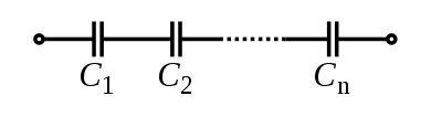
- Connected in series, the schematic diagram reveals that the separation distance, not the plate area, adds up. The capacitors each store instantaneous charge build-up equal to that of every other capacitor in the series. The total voltage difference from end to end is apportioned to each capacitor according to the inverse of its capacitance. The entire series acts as a capacitor smaller than any of its components.

- Capacitors are combined in series to achieve a higher working voltage, for example for smoothing a high voltage power supply. The voltage ratings, which are based on plate separation, add up, if capacitance and leakage currents for each capacitor are identical. In such an application, on occasion, series strings are connected in parallel, forming a matrix. The goal is to maximize the energy storage of the network without overloading any capacitor. For high-energy storage with capacitors in series, some safety considerations must be applied to ensure one capacitor failing and leaking current does not apply too much voltage to the other series capacitors.
- Series connection is also sometimes used to adapt polarized electrolytic capacitors for bipolar AC use. See electrolytic capacitor#Designing for reverse bias.
- Voltage distribution in parallel-to-series networks.
- To model the distribution of voltages from a single charged capacitor connected in parallel to a chain of capacitors in series :


- Note: This is only correct if all capacitance values are equal.
- The power transferred in this arrangement is:

Non-ideal behavior
Capacitors deviate from the ideal capacitor equation in a number of ways. Some of these, such as leakage current and parasitic effects are linear, or can be analyzed as nearly linear, and can be dealt with by adding virtual components to the equivalent circuit of an ideal capacitor. The usual methods of network analysis can then be applied. In other cases, such as with breakdown voltage, the effect is non-linear and ordinary (normal, eg, linear) network analysis cannot be used, the effect must be dealt with separately. There is yet another group, which may be linear but invalidate the assumption in the analysis that capacitance is a constant. Such an example is temperature dependence. Finally, combined parasitic effects such as inherent inductance, resistance, or dielectric losses can exhibit non-uniform behavior at variable frequencies of operation.
Breakdown voltage
Above a particular electric field, known as the dielectric strength Eds, the dielectric in a capacitor becomes conductive. The voltage at which this occurs is called the breakdown voltage of the device, and is given by the product of the dielectric strength and the separation between the conductors,[24]

The maximum energy that can be stored safely in a capacitor is limited by the breakdown voltage. Due to the scaling of capacitance and breakdown voltage with dielectric thickness, all capacitors made with a particular dielectric have approximately equal maximum energy density, to the extent that the dielectric dominates their volume.[25]
For air dielectric capacitors the breakdown field strength is of the order 2 to 5 MV/m; for mica the breakdown is 100 to 300 MV/m; for oil, 15 to 25 MV/m; it can be much less when other materials are used for the dielectric.[26] The dielectric is used in very thin layers and so absolute breakdown voltage of capacitors is limited. Typical ratings for capacitors used for general electronics applications range from a few volts to 1 kV. As the voltage increases, the dielectric must be thicker, making high-voltage capacitors larger per capacitance than those rated for lower voltages. The breakdown voltage is critically affected by factors such as the geometry of the capacitor conductive parts; sharp edges or points increase the electric field strength at that point and can lead to a local breakdown. Once this starts to happen, the breakdown quickly tracks through the dielectric until it reaches the opposite plate, leaving carbon behind and causing a short (or relatively low resistance) circuit. The results can be explosive as the short in the capacitor draws current from the surrounding circuitry and dissipates the energy.[27]
The usual breakdown route is that the field strength becomes large enough to pull electrons in the dielectric from their atoms thus causing conduction. Other scenarios are possible, such as impurities in the dielectric, and, if the dielectric is of a crystalline nature, imperfections in the crystal structure can result in an avalanche breakdown as seen in semi-conductor devices. Breakdown voltage is also affected by pressure, humidity and temperature.[28]
Equivalent circuit

An ideal capacitor only stores and releases electrical energy, without dissipating any. In reality, all capacitors have imperfections within the capacitor's material that create resistance. This is specified as the equivalent series resistance or ESR of a component. This adds a real component to the impedance:

As frequency approaches infinity, the capacitive impedance (or reactance) approaches zero and the ESR becomes significant. As the reactance becomes negligible, power dissipation approaches PRMS = VRMS² /RESR.
Similarly to ESR, the capacitor's leads add equivalent series inductance or ESL to the component. This is usually significant only at relatively high frequencies. As inductive reactance is positive and increases with frequency, above a certain frequency capacitance is canceled by inductance. High-frequency engineering involves accounting for the inductance of all connections and components.
If the conductors are separated by a material with a small conductivity rather than a perfect dielectric, then a small leakage current flows directly between them. The capacitor therefore has a finite parallel resistance,[18] and slowly discharges over time (time may vary greatly depending on the capacitor material and quality).
Q factor
The quality factor (or Q) of a capacitor is the ratio of its reactance to its resistance at a given frequency, and is a measure of its efficiency. The higher the Q factor of the capacitor, the closer it approaches the behavior of an ideal, lossless, capacitor.
The Q factor of a capacitor can be found through the following formula:

where is angular frequency, is the capacitance, is the capacitive reactance, and is the series resistance of the capacitor.


Ripple current
Ripple current is the AC component of an applied source (often a switched-mode power supply) whose frequency may be constant or varying. Ripple current causes heat to be generated within the capacitor due to the dielectric losses caused by the changing field strength together with the current flow across the slightly resistive supply lines or the electrolyte in the capacitor. The equivalent series resistance (ESR) is the amount of internal series resistance one would add to a perfect capacitor to model this.
Some types of capacitors, primarily tantalum and aluminum electrolytic capacitors, as well as some film capacitors have a specified rating value for maximum ripple current.
- Tantalum electrolytic capacitors with solid manganese dioxide electrolyte are limited by ripple current and generally have the highest ESR ratings in the capacitor family. Exceeding their ripple limits can lead to shorts and burning parts.
- Aluminum electrolytic capacitors, the most common type of electrolytic, suffer a shortening of life expectancy at higher ripple currents. If ripple current exceeds the rated value of the capacitor, it tends to result in explosive failure.
- Ceramic capacitors generally have no ripple current limitation and have some of the lowest ESR ratings.
- Film capacitors have very low ESR ratings but exceeding rated ripple current may cause degradation failures.
Capacitance instability
The capacitance of certain capacitors decreases as the component ages. In ceramic capacitors, this is caused by degradation of the dielectric. The type of dielectric, ambient operating and storage temperatures are the most significant aging factors, while the operating voltage has a smaller effect. The aging process may be reversed by heating the component above the Curie point. Aging is fastest near the beginning of life of the component, and the device stabilizes over time.[29] Electrolytic capacitors age as the electrolyte evaporates. In contrast with ceramic capacitors, this occurs towards the end of life of the component.
Temperature dependence of capacitance is usually expressed in parts per million (ppm) per °C. It can usually be taken as a broadly linear function but can be noticeably non-linear at the temperature extremes. The temperature coefficient can be either positive or negative, sometimes even amongst different samples of the same type. In other words, the spread in the range of temperature coefficients can encompass zero.
Capacitors, especially ceramic capacitors, and older designs such as paper capacitors, can absorb sound waves resulting in a microphonic effect. Vibration moves the plates, causing the capacitance to vary, in turn inducing AC current. Some dielectrics also generate piezoelectricity. The resulting interference is especially problematic in audio applications, potentially causing feedback or unintended recording. In the reverse microphonic effect, the varying electric field between the capacitor plates exerts a physical force, moving them as a speaker. This can generate audible sound, but drains energy and stresses the dielectric and the electrolyte, if any.
Current and voltage reversal
Current reversal occurs when the current changes direction. Voltage reversal is the change of polarity in a circuit. Reversal is generally described as the percentage of the maximum rated voltage that reverses polarity. In DC circuits, this is usually less than 100%, often in the range of 0 to 90%, whereas AC circuits experience 100% reversal.
In DC circuits and pulsed circuits, current and voltage reversal are affected by the damping of the system. Voltage reversal is encountered in RLC circuits that are under-damped. The current and voltage reverse direction, forming a harmonic oscillator between the inductance and capacitance. The current and voltage tends to oscillate and may reverse direction several times, with each peak being lower than the previous, until the system reaches an equilibrium. This is often referred to as ringing. In comparison, critically damped or over-damped systems usually do not experience a voltage reversal. Reversal is also encountered in AC circuits, where the peak current is equal in each direction.
For maximum life, capacitors usually need to be able to handle the maximum amount of reversal that a system may experience. An AC circuit experiences 100% voltage reversal, while under-damped DC circuits experience less than 100%. Reversal creates excess electric fields in the dielectric, causes excess heating of both the dielectric and the conductors, and can dramatically shorten the life expectancy of the capacitor. Reversal ratings often affect the design considerations for the capacitor, from the choice of dielectric materials and voltage ratings to the types of internal connections used.[30]
Dielectric absorption
Capacitors made with any type of dielectric material show some level of "dielectric absorption" or "soakage". On discharging a capacitor and disconnecting it, after a short time it may develop a voltage due to hysteresis in the dielectric. This effect is objectionable in applications such as precision sample and hold circuits or timing circuits. The level of absorption depends on many factors, from design considerations to charging time, since the absorption is a time-dependent process. However, the primary factor is the type of dielectric material. Capacitors such as tantalum electrolytic or polysulfone film exhibit relatively high absorption, while polystyrene or Teflon allow very small levels of absorption.[31] In some capacitors where dangerous voltages and energies exist, such as in flashtubes, television sets, and defibrillators, the dielectric absorption can recharge the capacitor to hazardous voltages after it has been shorted or discharged. Any capacitor containing over 10 joules of energy is generally considered hazardous, while 50 joules or higher is potentially lethal. A capacitor may regain anywhere from 0.01 to 20% of its original charge over a period of several minutes, allowing a seemingly safe capacitor to become surprisingly dangerous.[32][33][34][35][36]
Leakage
Leakage is equivalent to a resistor in parallel with the capacitor. Constant exposure to heat can cause dielectric breakdown and excessive leakage, a problem often seen in older vacuum tube circuits, particularly where oiled paper and foil capacitors were used. In many vacuum tube circuits, interstage coupling capacitors are used to conduct a varying signal from the plate of one tube to the grid circuit of the next stage. A leaky capacitor can cause the grid circuit voltage to be raised from its normal bias setting, causing excessive current or signal distortion in the downstream tube. In power amplifiers this can cause the plates to glow red, or current limiting resistors to overheat, even fail. Similar considerations apply to component fabricated solid-state (transistor) amplifiers, but owing to lower heat production and the use of modern polyester dielectric barriers this once-common problem has become relatively rare.
Electrolytic failure from disuse
Aluminum electrolytic capacitors are conditioned when manufactured by applying a voltage sufficient to initiate the proper internal chemical state. This state is maintained by regular use of the equipment. If a system using electrolytic capacitors is unused for a long period of time it can lose its conditioning. Sometimes they fail with a short circuit when next operated.
Capacitor types
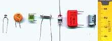
Practical capacitors are available commercially in many different forms. The type of internal dielectric, the structure of the plates and the device packaging all strongly affect the characteristics of the capacitor, and its applications.
Values available range from very low (picofarad range; while arbitrarily low values are in principle possible, stray (parasitic) capacitance in any circuit is the limiting factor) to about 5 kF supercapacitors.
Above approximately 1 microfarad electrolytic capacitors are usually used because of their small size and low cost compared with other types, unless their relatively poor stability, life and polarised nature make them unsuitable. Very high capacity supercapacitors use a porous carbon-based electrode material.
Dielectric materials
Most capacitors have a dielectric spacer, which increases their capacitance compared to air or a vacuum. In order to maximise the charge that a capacitor can hold, the dielectric material needs to have as high a permittivity as possible, while also having as high a breakdown voltage as possible. The dielectric also need to have as lower loss with frequency as possible
However, low value capacitors are available with a vacuum between their plates to allow extremely high voltage operation and low losses. Variable capacitors with their plates open to the atmosphere were commonly used in radio tuning circuits. Later designs use polymer foil dielectric between the moving and stationary plates, with no significant air space between the plates.
Several solid dielectrics are available, including paper, plastic, glass, mica and ceramic.
Paper was used extensively in older capacitors and offers relatively high voltage performance. However, paper absorbs moisture, and has been largely replaced by plastic film capacitors.
Most of the plastic films now used offer better stability and ageing performance than such older dielectrics such as oiled paper, which makes them useful in timer circuits, although they may be limited to relatively low operating temperatures and frequencies, because of the limitations of the plastic film being used. Large plastic film capacitors are used extensively in suppression circuits, motor start circuits, and power factor correction circuits.
Ceramic capacitors are generally small, cheap and useful for high frequency applications, although their capacitance varies strongly with voltage and temperature and they age poorly. They can also suffer from the piezoelectric effect. Ceramic capacitors are broadly categorized as class 1 dielectrics, which have predictable variation of capacitance with temperature or class 2 dielectrics, which can operate at higher voltage. Modern multilayer ceramics are usually quite small, but some types have inherently wide value tolerances, microphonic issues, and are usually physically brittle.
Glass and mica capacitors are extremely reliable, stable and tolerant to high temperatures and voltages, but are too expensive for most mainstream applications.
Electrolytic capacitors and supercapacitors are used to store small and larger amounts of energy, respectively, ceramic capacitors are often used in resonators, and parasitic capacitance occurs in circuits wherever the simple conductor-insulator-conductor structure is formed unintentionally by the configuration of the circuit layout.
Electrolytic capacitors use an aluminum or tantalum plate with an oxide dielectric layer. The second electrode is a liquid electrolyte, connected to the circuit by another foil plate. Electrolytic capacitors offer very high capacitance but suffer from poor tolerances, high instability, gradual loss of capacitance especially when subjected to heat, and high leakage current. Poor quality capacitors may leak electrolyte, which is harmful to printed circuit boards. The conductivity of the electrolyte drops at low temperatures, which increases equivalent series resistance. While widely used for power-supply conditioning, poor high-frequency characteristics make them unsuitable for many applications. Electrolytic capacitors suffer from self-degradation if unused for a period (around a year), and when full power is applied may short circuit, permanently damaging the capacitor and usually blowing a fuse or causing failure of rectifier diodes. For example, in older equipment, this may cause arcing in rectifier tubes. They can be restored before use by gradually applying the operating voltage, often performed on antique vacuum tube equipment over a period of thirty minutes by using a variable transformer to supply AC power. The use of this technique may be less satisfactory for some solid state equipment, which may be damaged by operation below its normal power range, requiring that the power supply first be isolated from the consuming circuits. Such remedies may not be applicable to modern high-frequency power supplies as these produce full output voltage even with reduced input.
Tantalum capacitors offer better frequency and temperature characteristics than aluminum, but higher dielectric absorption and leakage.[37]

Polymer capacitors (OS-CON, OC-CON, KO, AO) use solid conductive polymer (or polymerized organic semiconductor) as electrolyte and offer longer life and lower ESR at higher cost than standard electrolytic capacitors.
A feedthrough capacitor is a component that, while not serving as its main use, has capacitance and is used to conduct signals through a conductive sheet.
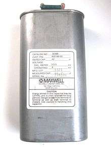
Several other types of capacitor are available for specialist applications. Supercapacitors store large amounts of energy. Supercapacitors made from carbon aerogel, carbon nanotubes, or highly porous electrode materials, offer extremely high capacitance (up to 5 kF as of 2010) and can be used in some applications instead of rechargeable batteries. Alternating current capacitors are specifically designed to work on line (mains) voltage AC power circuits. They are commonly used in electric motor circuits and are often designed to handle large currents, so they tend to be physically large. They are usually ruggedly packaged, often in metal cases that can be easily grounded/earthed. They also are designed with direct current breakdown voltages of at least five times the maximum AC voltage.
Voltage-dependent capacitors
The dielectric constant for a number of very useful dielectrics changes as a function of the applied electrical field, for example ferroelectric materials, so the capacitance for these devices is more complex. For example, in charging such a capacitor the differential increase in voltage with charge is governed by:

where the voltage dependence of capacitance, C(V), suggests that the capacitance is a function of the electric field strength, which in a large area parallel plate device is given by ε = V/d. This field polarizes the dielectric, which polarization, in the case of a ferroelectric, is a nonlinear S-shaped function of the electric field, which, in the case of a large area parallel plate device, translates into a capacitance that is a nonlinear function of the voltage.[38][39]
Corresponding to the voltage-dependent capacitance, to charge the capacitor to voltage V an integral relation is found:

which agrees with Q = CV only when C does not depend on voltage V.
By the same token, the energy stored in the capacitor now is given by
![dW =Q \, dV =\left[ \int_0^V\ dV' \ C(V') \right] \ dV \ .](../I/m/9cb57d174cb25b1859fa5a57390ef7a517d13ffc.svg)
Integrating:

where interchange of the order of integration is used.
The nonlinear capacitance of a microscope probe scanned along a ferroelectric surface is used to study the domain structure of ferroelectric materials.[40]
Another example of voltage dependent capacitance occurs in semiconductor devices such as semiconductor diodes, where the voltage dependence stems not from a change in dielectric constant but in a voltage dependence of the spacing between the charges on the two sides of the capacitor.[41] This effect is intentionally exploited in diode-like devices known as varicaps.
Frequency-dependent capacitors
If a capacitor is driven with a time-varying voltage that changes rapidly enough, at some frequency the polarization of the dielectric cannot follow the voltage. As an example of the origin of this mechanism, the internal microscopic dipoles contributing to the dielectric constant cannot move instantly, and so as frequency of an applied alternating voltage increases, the dipole response is limited and the dielectric constant diminishes. A changing dielectric constant with frequency is referred to as dielectric dispersion, and is governed by dielectric relaxation processes, such as Debye relaxation. Under transient conditions, the displacement field can be expressed as (see electric susceptibility):

indicating the lag in response by the time dependence of εr, calculated in principle from an underlying microscopic analysis, for example, of the dipole behavior in the dielectric. See, for example, linear response function.[42][43] The integral extends over the entire past history up to the present time. A Fourier transform in time then results in:

where εr(ω) is now a complex function, with an imaginary part related to absorption of energy from the field by the medium. See permittivity. The capacitance, being proportional to the dielectric constant, also exhibits this frequency behavior. Fourier transforming Gauss's law with this form for displacement field:

![=\left[ G(\omega) + j \omega C(\omega)\right] V(\omega) = \frac {V(\omega)}{Z(\omega)} \ ,](../I/m/22e60618abd65765cadbbd80aba0e20bb6914ec7.svg)
where j is the imaginary unit, V(ω) is the voltage component at angular frequency ω, G(ω) is the real part of the current, called the conductance, and C(ω) determines the imaginary part of the current and is the capacitance. Z(ω) is the complex impedance.
When a parallel-plate capacitor is filled with a dielectric, the measurement of dielectric properties of the medium is based upon the relation:

where a single prime denotes the real part and a double prime the imaginary part, Z(ω) is the complex impedance with the dielectric present, Ccmplx(ω) is the so-called complex capacitance with the dielectric present, and C0 is the capacitance without the dielectric.[44][45] (Measurement "without the dielectric" in principle means measurement in free space, an unattainable goal inasmuch as even the quantum vacuum is predicted to exhibit nonideal behavior, such as dichroism. For practical purposes, when measurement errors are taken into account, often a measurement in terrestrial vacuum, or simply a calculation of C0, is sufficiently accurate.[46])
Using this measurement method, the dielectric constant may exhibit a resonance at certain frequencies corresponding to characteristic response frequencies (excitation energies) of contributors to the dielectric constant. These resonances are the basis for a number of experimental techniques for detecting defects. The conductance method measures absorption as a function of frequency.[47] Alternatively, the time response of the capacitance can be used directly, as in deep-level transient spectroscopy.[48]
Another example of frequency dependent capacitance occurs with MOS capacitors, where the slow generation of minority carriers means that at high frequencies the capacitance measures only the majority carrier response, while at low frequencies both types of carrier respond.[49][50]
At optical frequencies, in semiconductors the dielectric constant exhibits structure related to the band structure of the solid. Sophisticated modulation spectroscopy measurement methods based upon modulating the crystal structure by pressure or by other stresses and observing the related changes in absorption or reflection of light have advanced our knowledge of these materials.[51]
Structure

The arrangement of plates and dielectric has many variations depending on the desired ratings of the capacitor. For small values of capacitance (microfarads and less), ceramic disks use metallic coatings, with wire leads bonded to the coating. Larger values can be made by multiple stacks of plates and disks. Larger value capacitors usually use a metal foil or metal film layer deposited on the surface of a dielectric film to make the plates, and a dielectric film of impregnated paper or plastic – these are rolled up to save space. To reduce the series resistance and inductance for long plates, the plates and dielectric are staggered so that connection is made at the common edge of the rolled-up plates, not at the ends of the foil or metalized film strips that comprise the plates.
The assembly is encased to prevent moisture entering the dielectric – early radio equipment used a cardboard tube sealed with wax. Modern paper or film dielectric capacitors are dipped in a hard thermoplastic. Large capacitors for high-voltage use may have the roll form compressed to fit into a rectangular metal case, with bolted terminals and bushings for connections. The dielectric in larger capacitors is often impregnated with a liquid to improve its properties.

Capacitors may have their connecting leads arranged in many configurations, for example axially or radially. "Axial" means that the leads are on a common axis, typically the axis of the capacitor's cylindrical body – the leads extend from opposite ends. Radial leads might more accurately be referred to as tandem; they are rarely actually aligned along radii of the body's circle, so the term is inexact, although universal. The leads (until bent) are usually in planes parallel to that of the flat body of the capacitor, and extend in the same direction; they are often parallel as manufactured.
Small, cheap discoidal ceramic capacitors have existed since the 1930s, and remain in widespread use. Since the 1980s, surface mount packages for capacitors have been widely used. These packages are extremely small and lack connecting leads, allowing them to be soldered directly onto the surface of printed circuit boards. Surface mount components avoid undesirable high-frequency effects due to the leads and simplify automated assembly, although manual handling is made difficult due to their small size.
Mechanically controlled variable capacitors allow the plate spacing to be adjusted, for example by rotating or sliding a set of movable plates into alignment with a set of stationary plates. Low cost variable capacitors squeeze together alternating layers of aluminum and plastic with a screw. Electrical control of capacitance is achievable with varactors (or varicaps), which are reverse-biased semiconductor diodes whose depletion region width varies with applied voltage. They are used in phase-locked loops, amongst other applications.
Capacitor markings
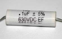
Most capacitors have numbers printed on their bodies to indicate their electrical characteristics. Larger capacitors like electrolytics usually display the actual capacitance together with the unit, for example, 220 μF. Smaller capacitors like ceramics, however, use a shorthand-notation consisting of three digits and a letter, where the digits indicate the capacitance in pF, calculated as XY × 10Z for digits XYZ, and the letter indicates the tolerance. Common tolerance indications are J, K, and M for ±5%, ±10%, and ±20%, respectively.
Additionally, the capacitor may be labeled with its working voltage, temperature and other relevant characteristics.
For typographical reasons, some manufacturers print MF on capacitors to indicate microfarads (μF).[52]
Example
A capacitor labeled or designated as 473K 330V has a capacitance of 47 × 103 pF = 47 nF (±10%) with a maximum working voltage of 330 V. The working voltage of a capacitor is nominally the highest voltage that may be applied across it without undue risk of breaking down the dielectric layer.
Historical
In the past, alternate capacitance subunits were used in historical electronic books; "mfd" and "mf" for microfarad (µF); "mmfd", "mmf", "µµF" for picofarad (pF); but are rarely used any more.[53][54]
Applications

Energy storage
A capacitor can store electric energy when disconnected from its charging circuit, so it can be used like a temporary battery, or like other types of rechargeable energy storage system.[55] Capacitors are commonly used in electronic devices to maintain power supply while batteries are being changed. (This prevents loss of information in volatile memory.)
Conventional capacitors provide less than 360 joules per kilogram of specific energy, whereas a conventional alkaline battery has a density of 590 kJ/kg. There is an intermediate solution: Supercapacitors, which can accept and deliver charge much faster than batteries, and tolerate many more charge and discharge cycles than rechargeable batteries. They are however 10 times larger than conventional batteries for a given charge.
In car audio systems, large capacitors store energy for the amplifier to use on demand. Also for a flash tube a capacitor is used to hold the high voltage.
Digital memory
In the 1930s, John Atanasoff applied the principle of energy storage in capacitors to construct dynamic digital memories for the first binary computers that used electron tubes for logic.[4]
Pulsed power and weapons
Groups of large, specially constructed, low-inductance high-voltage capacitors (capacitor banks) are used to supply huge pulses of current for many pulsed power applications. These include electromagnetic forming, Marx generators, pulsed lasers (especially TEA lasers), pulse forming networks, radar, fusion research, and particle accelerators.
Large capacitor banks (reservoir) are used as energy sources for the exploding-bridgewire detonators or slapper detonators in nuclear weapons and other specialty weapons. Experimental work is under way using banks of capacitors as power sources for electromagnetic armour and electromagnetic railguns and coilguns.
Power conditioning
Reservoir capacitors are used in power supplies where they smooth the output of a full or half wave rectifier. They can also be used in charge pump circuits as the energy storage element in the generation of higher voltages than the input voltage.
Capacitors are connected in parallel with the power circuits of most electronic devices and larger systems (such as factories) to shunt away and conceal current fluctuations from the primary power source to provide a "clean" power supply for signal or control circuits. Audio equipment, for example, uses several capacitors in this way, to shunt away power line hum before it gets into the signal circuitry. The capacitors act as a local reserve for the DC power source, and bypass AC currents from the power supply. This is used in car audio applications, when a stiffening capacitor compensates for the inductance and resistance of the leads to the lead-acid car battery.
Power factor correction

In electric power distribution, capacitors are used for power factor correction. Such capacitors often come as three capacitors connected as a three phase load. Usually, the values of these capacitors are given not in farads but rather as a reactive power in volt-amperes reactive (var). The purpose is to counteract inductive loading from devices like electric motors and transmission lines to make the load appear to be mostly resistive. Individual motor or lamp loads may have capacitors for power factor correction, or larger sets of capacitors (usually with automatic switching devices) may be installed at a load center within a building or in a large utility substation.
Suppression and coupling
Signal coupling
Because capacitors pass AC but block DC signals (when charged up to the applied dc voltage), they are often used to separate the AC and DC components of a signal. This method is known as AC coupling or "capacitive coupling". Here, a large value of capacitance, whose value need not be accurately controlled, but whose reactance is small at the signal frequency, is employed.
Decoupling
A decoupling capacitor is a capacitor used to protect one part of a circuit from the effect of another, for instance to suppress noise or transients. Noise caused by other circuit elements is shunted through the capacitor, reducing the effect they have on the rest of the circuit. It is most commonly used between the power supply and ground. An alternative name is bypass capacitor as it is used to bypass the power supply or other high impedance component of a circuit.
Decoupling capacitors need not always be discrete components. Capacitors used in these applications may be built into a printed circuit board, between the various layers. These are often referred to as embedded capacitors.[56] The layers in the board contributing to the capacitive properties also function as power and ground planes, and have a dielectric in between them, enabling them to operate as a parallel plate capacitor.
High-pass and low-pass filters
Noise suppression, spikes, and snubbers
When an inductive circuit is opened, the current through the inductance collapses quickly, creating a large voltage across the open circuit of the switch or relay. If the inductance is large enough, the energy may generate a spark, causing the contact points to oxidize, deteriorate, or sometimes weld together, or destroying a solid-state switch. A snubber capacitor across the newly opened circuit creates a path for this impulse to bypass the contact points, thereby preserving their life; these were commonly found in contact breaker ignition systems, for instance. Similarly, in smaller scale circuits, the spark may not be enough to damage the switch but may still radiate undesirable radio frequency interference (RFI), which a filter capacitor absorbs. Snubber capacitors are usually employed with a low-value resistor in series, to dissipate energy and minimize RFI. Such resistor-capacitor combinations are available in a single package.
Capacitors are also used in parallel to interrupt units of a high-voltage circuit breaker in order to equally distribute the voltage between these units. In this case they are called grading capacitors.
In schematic diagrams, a capacitor used primarily for DC charge storage is often drawn vertically in circuit diagrams with the lower, more negative, plate drawn as an arc. The straight plate indicates the positive terminal of the device, if it is polarized (see electrolytic capacitor).
Motor starters
In single phase squirrel cage motors, the primary winding within the motor housing is not capable of starting a rotational motion on the rotor, but is capable of sustaining one. To start the motor, a secondary "start" winding has a series non-polarized starting capacitor to introduce a lead in the sinusoidal current. When the secondary (start) winding is placed at an angle with respect to the primary (run) winding, a rotating electric field is created. The force of the rotational field is not constant, but is sufficient to start the rotor spinning. When the rotor comes close to operating speed, a centrifugal switch (or current-sensitive relay in series with the main winding) disconnects the capacitor. The start capacitor is typically mounted to the side of the motor housing. These are called capacitor-start motors, that have relatively high starting torque. Typically they can have up-to four times as much starting torque than a split-phase motor and are used on applications such as compressors, pressure washers and any small device requiring high starting torques.
Capacitor-run induction motors have a permanently connected phase-shifting capacitor in series with a second winding. The motor is much like a two-phase induction motor.
Motor-starting capacitors are typically non-polarized electrolytic types, while running capacitors are conventional paper or plastic film dielectric types.
Signal processing
The energy stored in a capacitor can be used to represent information, either in binary form, as in DRAMs, or in analogue form, as in analog sampled filters and CCDs. Capacitors can be used in analog circuits as components of integrators or more complex filters and in negative feedback loop stabilization. Signal processing circuits also use capacitors to integrate a current signal.
Tuned circuits
Capacitors and inductors are applied together in tuned circuits to select information in particular frequency bands. For example, radio receivers rely on variable capacitors to tune the station frequency. Speakers use passive analog crossovers, and analog equalizers use capacitors to select different audio bands.
The resonant frequency f of a tuned circuit is a function of the inductance (L) and capacitance (C) in series, and is given by:

where L is in henries and C is in farads.
Sensing
- Main article: capacitive sensing
- Main article: Capacitive displacement sensor
Most capacitors are designed to maintain a fixed physical structure. However, various factors can change the structure of the capacitor, and the resulting change in capacitance can be used to sense those factors.
Changing the dielectric:
- The effects of varying the characteristics of the dielectric can be used for sensing purposes. Capacitors with an exposed and porous dielectric can be used to measure humidity in air. Capacitors are used to accurately measure the fuel level in airplanes; as the fuel covers more of a pair of plates, the circuit capacitance increases. Squeezing the dielectric can change a capacitor at a few tens of bar pressure sufficiently that it can be used as a pressure sensor.[57] A selected, but otherwise standard, polymer dielectric capacitor, when immersed in a compatible gas or liquid, can work usefully as a very low cost pressure sensor up to many hundreds of bar.
Changing the distance between the plates:
- Capacitors with a flexible plate can be used to measure strain or pressure. Industrial pressure transmitters used for process control use pressure-sensing diaphragms, which form a capacitor plate of an oscillator circuit. Capacitors are used as the sensor in condenser microphones, where one plate is moved by air pressure, relative to the fixed position of the other plate. Some accelerometers use MEMS capacitors etched on a chip to measure the magnitude and direction of the acceleration vector. They are used to detect changes in acceleration, in tilt sensors, or to detect free fall, as sensors triggering airbag deployment, and in many other applications. Some fingerprint sensors use capacitors. Additionally, a user can adjust the pitch of a theremin musical instrument by moving their hand since this changes the effective capacitance between the user's hand and the antenna.
Changing the effective area of the plates:
- Capacitive touch switches are now used on many consumer electronic products.
Oscillators
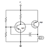
A capacitor can possess spring-like qualities in an oscillator circuit. In the image example, a capacitor acts to influence the biasing voltage at the npn transistor's base. The resistance values of the voltage-divider resistors and the capacitance value of the capacitor together control the oscillatory frequency.
Producing light
A light-emitting capacitor is made from a dielectric that uses phosphorescence to produce light. If one of the conductive plates is made with a transparent material, the light is visible. Light-emitting capacitors are used in the construction of electroluminescent panels, for applications such as backlighting for laptop computers. In this case, the entire panel is a capacitor used for the purpose of generating light.
Hazards and safety
The hazards posed by a capacitor are usually determined, foremost, by the amount of energy stored, which is the cause of things like electrical burns or heart fibrillation. Factors such as voltage and chassis material are of secondary consideration, which are more related to how easily a shock can be initiated rather than how much damage can occur.[36]
Capacitors may retain a charge long after power is removed from a circuit; this charge can cause dangerous or even potentially fatal shocks or damage connected equipment. For example, even a seemingly innocuous device such as a disposable-camera flash unit, powered by a 1.5 volt AA battery, has a capacitor which may contain over 15 joules of energy and be charged to over 300 volts. This is easily capable of delivering a shock. Service procedures for electronic devices usually include instructions to discharge large or high-voltage capacitors, for instance using a Brinkley stick. Capacitors may also have built-in discharge resistors to dissipate stored energy to a safe level within a few seconds after power is removed. High-voltage capacitors are stored with the terminals shorted, as protection from potentially dangerous voltages due to dielectric absorption or from transient voltages the capacitor may pick up from static charges or passing weather events.[36]
Some old, large oil-filled paper or plastic film capacitors contain polychlorinated biphenyls (PCBs). It is known that waste PCBs can leak into groundwater under landfills. Capacitors containing PCB were labelled as containing "Askarel" and several other trade names. PCB-filled paper capacitors are found in very old (pre-1975) fluorescent lamp ballasts, and other applications.
Capacitors may catastrophically fail when subjected to voltages or currents beyond their rating, or as they reach their normal end of life. Dielectric or metal interconnection failures may create arcing that vaporizes the dielectric fluid, resulting in case bulging, rupture, or even an explosion. Capacitors used in RF or sustained high-current applications can overheat, especially in the center of the capacitor rolls. Capacitors used within high-energy capacitor banks can violently explode when a short in one capacitor causes sudden dumping of energy stored in the rest of the bank into the failing unit. High voltage vacuum capacitors can generate soft X-rays even during normal operation. Proper containment, fusing, and preventive maintenance can help to minimize these hazards.
High-voltage capacitors may benefit from a pre-charge to limit in-rush currents at power-up of high voltage direct current (HVDC) circuits. This extends the life of the component and may mitigate high-voltage hazards.
-

Swollen caps of electrolytic capacitors – special design of semi-cut caps prevents capacitors from bursting
-
This high-energy capacitor from a defibrillator can deliver over 500 joules of energy. A resistor is connected between the terminals for safety, to allow the stored energy to be released.
-

Catastrophic failure
See also
References
- ↑ Alexander, Charles; Sadiku, Matthew. Fundamentals of Electric Circuits (3 ed.). McGraw-Hill. p. 206.
- 1 2 Duff, Wilmer (1908–1916). A Text-Book of Physics (4 ed.). Philadelphia: P. Blakiston's Son & Co. p. 361. Retrieved 1 December 2016.
- ↑ Bird, John (2010). Electrical and Electronic Principles and Technology. Routledge. pp. 63–76. ISBN 9780080890562. Retrieved 2013-03-17.
- 1 2 Floyd, Thomas (1984–2005). Electronic Devices (7 ed.). Upper Saddle River, NJ: Pearson Education. p. 10. ISBN 0-13-127827-4.
- ↑ Williams, Henry Smith. "A History of Science Volume II, Part VI: The Leyden Jar Discovered". Retrieved 2013-03-17.
- ↑ Keithley, Joseph F. (1999). The Story of Electrical and Magnetic Measurements: From 500 BC to the 1940s. John Wiley & Sons. p. 23. ISBN 9780780311930. Retrieved 2013-03-17.
- ↑ Houston, Edwin J. (1905). Electricity in Every-day Life. P. F. Collier & Son. p. 71. Retrieved 2013-03-17.
- ↑ Isaacson, Walter (2003). Benjamin Franklin: An American Life. Simon and Schuster. p. 136. ISBN 9780743260848. Retrieved 2013-03-17.
- ↑ Franklin, Benjamin (1749-04-29). "Experiments & Observations on Electricity: Letter IV to Peter Collinson" (PDF). p. 28. Retrieved 2009-08-09.
- ↑ Morse, Robert A. (September 2004). "Franklin and Electrostatics—Ben Franklin as my Lab Partner" (PDF). Wright Center for Science Education. Tufts University. p. 23. Retrieved 2009-08-10.
After Volta’s discovery of the electrochemical cell in 1800, the term was then applied to a group of electrochemical cells
- ↑ "eFunda: Glossary: Units: Electric Capacitance: Jar". eFunda. Retrieved 2013-03-17.
- ↑ "Sketch of Alessandro Volta". The Popular Science Monthly. New York: Bonnier Corporation: 118–119. May 1892. ISSN 0161-7370.
- 1 2 3 4 Ho, J.; Jow, R.; Boggs, S. (Jan 2010). "Historical Introduction to Capacitor Technology" (PDF). IEEE Elect. Insul. Mag. IEEE. 26 (1): 20–25. doi:10.1109/mei.2010.5383924.
- ↑ US 2800616, Becker, H.I., "Low voltage electrolytic capacitor", issued 1957-07-23
- ↑ A brief history of supercapacitors AUTUMN 2007 Batteries & Energy Storage Technology
- 1 2 Ulaby, p.168
- ↑ Ulaby, p.157
- 1 2 Ulaby, p.169
- ↑ Hammond, Percy (1964). Electromagnetism for Engineers: An Introductory Course. The Commonwealth and International Library of Science, Technology, Engineering and Liberal Studies. Applied Electricity and Electronics Division. 3. Pergamon Press. pp. 44–45.
- ↑ Dorf, p.263
- ↑ Dorf, p.260
- ↑ "Capacitor charging and discharging". All About Circuits. Retrieved 2009-02-19.
- ↑ Pillai, K. P. P. (1970). "Fringing field of finite parallel-plate capacitors". Proceedings of the Institution of Electrical Engineers. 117 (6): 1201–1204. doi:10.1049/piee.1970.0232.
- ↑ Ulaby, p.170
- ↑ Pai, S. T.; Qi Zhang (1995). Introduction to High Power Pulse Technology. Advanced Series in Electrical and Computer Engineering. 10. World Scientific. ISBN 9789810217143. Retrieved 2013-03-17.
- ↑ Dyer, Stephen A. (2004). Wiley Survey of Instrumentation and Measurement. John Wiley & Sons. p. 397. ISBN 9780471221654. Retrieved 2013-03-17.
- ↑ Scherz, Paul (2006). Practical Electronics for Inventors (2nd ed.). McGraw Hill Professional. p. 100. ISBN 9780071776448. Retrieved 2013-03-17.
- ↑ Bird, John (2007). Electrical Circuit Theory and Technology. Routledge. p. 501. ISBN 9780750681391. Retrieved 2013-03-17.
- ↑ "Ceramic Capacitor Aging Made Simple". Johanson Dielectrics. 2012-05-21. Retrieved 2013-03-17.
- ↑ "The Effect of Reversal on Capacitor Life" (PDF). Engineering Bulletin 96-004. Sorrento Electronics. November 2003. Archived from the original (PDF) on 2014-07-14. Retrieved 2013-03-17.
- ↑ Kaiser, Cletus J. (1993) The Capacitor Handbook. Springer
- ↑ Electronics. McGraw-Hill 1960 p. 90
- ↑ Xenon Strobe and Flash Safety Hints. donklipstein.com. May 29, 2006
- ↑ Prutchi, David (2012) Exploring Quantum Physics through Hands-on Projects. John Wiley and Sons. p. 10. ISBN 1118170709.
- ↑ Dixit, J. B. and Yadav, Amit (2010) Electrical Power Quality. University Science Press. p. 63. ISBN 9380386745.
- 1 2 3 Winburn (1990) Practical Laser Safety Second Edition. Marcel-Dekker Inc. p. 189. ISBN 0824782402.
- ↑ Guinta, Steve. "Ask The Applications Engineer – 21". Analog Devices. Retrieved 2013-03-17.
- ↑ Carlos Paz de Araujo, Ramamoorthy Ramesh, George W Taylor (Editors) (2001). Science and Technology of Integrated Ferroelectrics: Selected Papers from Eleven Years of the Proceedings of the International Symposium on Integrated Ferroelectrics. CRC Press. Figure 2, p. 504. ISBN 90-5699-704-1.
- ↑ Solomon Musikant (1991). What Every Engineer Should Know about Ceramics. CRC Press. Figure 3.9, p. 43. ISBN 0-8247-8498-7.
- ↑ Yasuo Cho (2005). Scanning Nonlinear Dielectric Microscope (in Polar Oxides; R Waser, U Böttger & S Tiedke, editors ed.). Wiley-VCH. Chapter 16. ISBN 3-527-40532-1.
- ↑ Simon M. Sze; Kwok K. Ng (2006). Physics of Semiconductor Devices (3rd ed.). Wiley. Figure 25, p. 121. ISBN 0-470-06830-2.
- ↑ Gabriele Giuliani; Giovanni Vignale (2005). Quantum Theory of the Electron Liquid. Cambridge University Press. p. 111. ISBN 0-521-82112-6.
- ↑ Jørgen Rammer (2007). Quantum Field Theory of Non-equilibrium States. Cambridge University Press. p. 158. ISBN 0-521-87499-8.
- ↑ Horst Czichos; Tetsuya Saito; Leslie Smith (2006). Springer Handbook of Materials Measurement Methods. Springer. p. 475. ISBN 3-540-20785-6.
- ↑ William Coffey; Yu. P. Kalmykov (2006). Fractals, diffusion and relaxation in disordered complex systems..Part A. Wiley. p. 17. ISBN 0-470-04607-4.
- ↑ J. Obrzut, A. Anopchenko and R. Nozaki, "Broadband Permittivity Measurements of High Dielectric Constant Films", Proceedings of the IEEE: Instrumentation and Measurement Technology Conference, 2005, pp. 1350–1353, 16–19 May 2005, Ottawa ISBN 0-7803-8879-8 doi:10.1109/IMTC.2005.1604368
- ↑ Dieter K Schroder (2006). Semiconductor Material and Device Characterization (3rd ed.). Wiley. p. 347 ff. ISBN 0-471-73906-5.
- ↑ Dieter K Schroder (2006). Semiconductor Material and Device Characterization (3rd ed.). Wiley. p. 270 ff. ISBN 0-471-73906-5.
- ↑ Simon M. Sze; Kwok K. Ng (2006). Physics of Semiconductor Devices (3rd ed.). Wiley. p. 217. ISBN 0-470-06830-2.
- ↑ Safa O. Kasap; Peter Capper (2006). Springer Handbook of Electronic and Photonic Materials. Springer. Figure 20.22, p. 425.
- ↑ PY Yu; Manuel Cardona (2001). Fundamentals of Semiconductors (3rd ed.). Springer. p. §6.6 Modulation Spectroscopy. ISBN 3-540-25470-6.
- ↑ Kaplan, Daniel M.; White, Christopher G. Hands-On Electronics: A Practical Introduction to Analog and Digital Circuits. p. 19.
- ↑ Capacitor MF-MMFD Conversion Chart; Just Radios.
- ↑ Fundamentals of Electronics - Volume 1b - Basic Electricity - Alternating Current; Bureau of Naval Personnel; 1965; page 197.
- ↑ Miller, Charles. Illustrated Guide to the National Electrical Code, p. 445 (Cengage Learning 2011).
- ↑ Alam, Mohammed; Michael H. Azarian; Michael Osterman; Michael Pecht (2010). "Effectiveness of embedded capacitors in reducing the number of surface mount capacitors for decoupling applications". Circuit World. 36 (1): 22. doi:10.1108/03056121011015068.
- ↑ Downie, Neil A and Mathilde Pradier, 'Method and apparatus for monitoring fluid pressure", US Patent 7526961 (2009)
Bibliography
- Dorf, Richard C.; Svoboda, James A. (2001). Introduction to Electric Circuits (5th ed.). New York: John Wiley & Sons. ISBN 9780471386896.
- Philosophical Transactions of the Royal Society LXXII, Appendix 8, 1782 (Volta coins the word condenser)
- Ulaby, Fawwaz Tayssir (1999). Fundamentals of Applied Electromagnetics. Upper Saddle River, New Jersey: Prentice Hall. ISBN 9780130115546.
- Zorpette, Glenn (2005). "Super Charged: A Tiny South Korean Company is Out to Make Capacitors Powerful enough to Propel the Next Generation of Hybrid-Electric Cars". IEEE Spectrum (North American ed.). 42 (1): 32. doi:10.1109/MSPEC.2005.1377872.
- Deshpande, R.P. (2014). Capacitors. McGraw-Hill. ISBN 9780071848565.
External links
| The Wikibook Electronics has a page on the topic of: Capacitors |
| Look up capacitor in Wiktionary, the free dictionary. |
| Wikimedia Commons has media related to Capacitors. |
- What exactly is a capacitor?
- The First Condenser – A Beer Glass - SparkMuseum
- How Capacitors Work - Howstuffworks
- Introduction to Capacitors - CapSite
- Capacitor Tutorial
- Low ESR Capacitor Manufacturers