Internal combustion engine
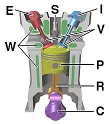
C – crankshaft.
E – exhaust camshaft.
I – inlet camshaft.
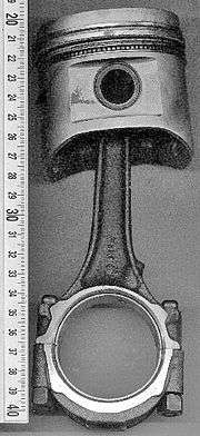
P – piston.
R – connecting rod.
S – spark plug.
V – valves. red: exhaust, blue: intake.
W – cooling water jacket.
gray structure – engine block.

An internal combustion engine (ICE) is a heat engine where the combustion of a fuel occurs with an oxidizer (usually air) in a combustion chamber that is an integral part of the working fluid flow circuit. In an internal combustion engine the expansion of the high-temperature and high-pressure gases produced by combustion apply direct force to some component of the engine. The force is applied typically to pistons, turbine blades, rotor or a nozzle. This force moves the component over a distance, transforming chemical energy into useful mechanical energy.
The first commercially successful internal combustion engine was created by Étienne Lenoir around 1859[1] and the first modern internal combustion engine was created in 1876 by Nikolaus Otto (see Otto engine).
The term internal combustion engine usually refers to an engine in which combustion is intermittent, such as the more familiar four-stroke and two-stroke piston engines, along with variants, such as the six-stroke piston engine and the Wankel rotary engine. A second class of internal combustion engines use continuous combustion: gas turbines, jet engines and most rocket engines, each of which are internal combustion engines on the same principle as previously described.[1][2] Firearms are also a form of internal combustion engine.[2]
Internal combustion engines are quite different from external combustion engines, such as steam or Stirling engines, in which the energy is delivered to a working fluid not consisting of, mixed with, or contaminated by combustion products. Working fluids can be air, hot water, pressurized water or even liquid sodium, heated in a boiler. ICEs are usually powered by energy-dense fuels such as gasoline or diesel, liquids derived from fossil fuels. While there are many stationary applications, most ICEs are used in mobile applications and are the dominant power supply for vehicles such as cars, aircraft, and boats.
Typically an ICE is fed with fossil fuels like natural gas or petroleum products such as gasoline, diesel fuel or fuel oil. There's a growing usage of renewable fuels like biodiesel for compression ignition engines and bioethanol or methanol for spark ignition engines. Hydrogen is sometimes used, and can be made from either fossil fuels or renewable energy.
History
Various scientists and engineers contributed to the development of internal combustion engines. In 1791, John Barber developed a turbine. In 1794 Thomas Mead patented a gas engine. Also in 1794 Robert Street patented an internal combustion engine, which was also the first to use liquid fuel, and built an engine around that time. In 1798, John Stevens built the first American internal combustion engine. In 1807, Swiss engineer François Isaac de Rivaz built an internal combustion engine ignited by electric spark. In 1823, Samuel Brown patented the first internal combustion engine to be applied industrially.
In 1860, Belgian Jean Joseph Etienne Lenoir produced a gas-fired internal combustion engine. In 1864, Nikolaus Otto patented the first atmospheric gas engine. In 1872, American George Brayton invented the first commercial liquid-fuelled internal combustion engine. In 1876, Nikolaus Otto, working with Gottlieb Daimler and Wilhelm Maybach, patented the compressed charge, four-cycle engine. In 1879, Karl Benz patented a reliable two-stroke gas engine. In 1892, Rudolf Diesel developed the first compressed charge, compression ignition engine. In 1926, Robert Goddard launched the first liquid-fueled rocket. In 1939, the Heinkel He 178 became the world's first jet aircraft.
Etymology
At one time, the word engine (via Old French, from Latin ingenium, "ability") meant any piece of machinery — a sense that persists in expressions such as siege engine. A "motor" (from Latin motor, "mover") is any machine that produces mechanical power. Traditionally, electric motors are not referred to as "Engines"; however, combustion engines are often referred to as "motors." (An electric engine refers to a locomotive operated by electricity.)
In boating an internal combustion engine that is installed in the hull is referred to as an engine, but the engines that sit on the transom are referred to as motors.[3]
Applications

Reciprocating piston engines are by far the most common power source for land and water vehicles, including automobiles, motorcycles, ships and to a lesser extent, locomotives (some are electrical but most use Diesel engines[4][5]). Rotary engines of the Wankel design are used in some automobiles, aircraft and motorcycles.
Where very high power-to-weight ratios are required, internal combustion engines appear in the form of combustion turbines or Wankel engines. Powered aircraft typically uses an ICE which may be a reciprocating engine. Airplanes can instead use jet engines and helicopters can instead employ turboshafts; both of which are types of turbines. In addition to providing propulsion, airliners may employ a separate ICE as an auxiliary power unit. Wankel engines are fitted to many unmanned aerial vehicles.
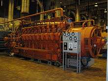
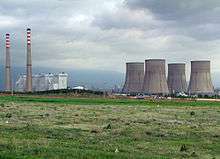
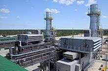
ICEs drive some of the large electric generators that power electrical grids. They are found in the form of combustion turbines in combined cycle power plants with a typical electrical output in the range of 100 MW to 1 GW. The high temperature exhaust is used to boil and superheat water to run a steam turbine. Thus, the efficiency is higher because more energy is extracted from the fuel than what could be extracted by the combustion turbine alone. In combined cycle power plants efficiencies in the range of 50% to 60% are typical. In a smaller scale Diesel generators are used for backup power and for providing electrical power to areas not connected to an electric grid.
Small engines (usually 2‐stroke gasoline engines) are a common power source for lawnmowers, string trimmers, chain saws, leafblowers, pressure washers, snowmobiles, jet skis, outboard motors, mopeds, and motorcycles.
Classification
There are several possible ways to classify internal combustion engines.
- By number of strokes
- Clerk Cycle 1879 [6]
- Day Cycle
- By type of ignition
- Compression-ignition engine
- Spark-ignition engine (commonly found as gasoline engines)
- By mechanical/thermodynamical cycle (these 2 cycles do not encompass all reciprocating engines, and are infrequently used):
Continuous combustion:
- The following jet engine types are also gas turbines types:
Reciprocating engines
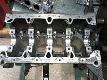
Structure

The base of a reciprocating internal combustion engine is the engine block, which is typically made of cast iron or aluminium. The engine block contains the cylinders. In engines with more than one cylinder they are usually arranged either in 1 row (straight engine) or 2 rows (boxer engine or V engine); 3 rows are occasionally used (W engine) in contemporary engines, and other engine configurations are possible and have been used. Single cylinder engines are common for motorcycles and in small engines of machinery. Water-cooled engines contain passages in the engine block where cooling fluid circulates (the water jacket). Some small engines are air-cooled, and instead of having a water jacket the cylinder block has fins protruding away from it to cool by directly transferring heat to the air. The cylinder walls are usually finished by honing to obtain a cross hatch, which is better able to retain the oil. A too rough surface would quickly harm the engine by excessive wear on the piston.
The pistons are short cylindrical parts which seal one end of the cylinder from the high pressure of the compressed air and combustion products and slide continuously within it while the engine is in operation. The top wall of the piston is termed its crown and is typically flat or concave. Some two-stroke engines use pistons with a deflector head. Pistons are open at the bottom and hollow except for an integral reinforcement structure (the piston web). When an engine is working the gas pressure in the combustion chamber exerts a force on the piston crown which is transferred through its web to a gudgeon pin. Each piston has rings fitted around its circumference that mostly prevent the gases from leaking into the crankcase or the oil into the combustion chamber. A ventilation system drives the small amount of gas that escape past the pistons during normal operation (the blow-by gases) out of the crankcase so that it does not accumulate contaminating the oil and creating corrosion. In two-stroke gasoline engines the crankcase is part of the air–fuel path and due to the continuous flow of it they do not need a separate crankcase ventilation system.

The cylinder head is attached to the engine block by numerous bolts or studs. It has several functions. The cylinder head seals the cylinders on the side opposite to the pistons; it contains short ducts (the ports) for intake and exhaust and the associated intake valves that open to let the cylinder be filled with fresh air and exhaust valves that open to allow the combustion gases to escape. However, 2-stroke crankcase scavenged engines connect the gas ports directly to the cylinder wall without poppet valves; the piston controls their opening and occlusion instead. The cylinder head also holds the spark plug in the case of spark ignition engines and the injector for engines that use direct injection. All CI engines use fuel injection, usually direct injection but some engines instead use indirect injection. SI engines can use a carburetor or fuel injection as port injection or direct injection. Most SI engines have a single spark plug per cylinder but some have 2. A head gasket prevents the gas from leaking between the cylinder head and the engine block. The opening and closing of the valves is controlled by one or several camshafts and springs—or in some engines—a desmodromic mechanism that uses no springs. The camshaft may press directly the stem of the valve or may act upon a rocker arm, again, either directly or through a pushrod.
The crankcase is sealed at the bottom with a sump that collects the falling oil during normal operation to be cycled again. The cavity created between the cylinder block and the sump houses a crankshaft that converts the reciprocating motion of the pistons to rotational motion. The crankshaft is held in place relative to the engine block by main bearings, which allow it to rotate. Bulkheads in the crankcase form a half of every main bearing; the other half is a detachable cap. In some cases a single main bearing deck is used rather than several smaller caps. A connecting rod is connected to offset sections of the crankshaft (the crankpins) in one end and to the piston in the other end through the gudgeon pin and thus transfers the force and translates the reciprocating motion of the pistons to the circular motion of the crankshaft. The end of the connecting rod attached to the gudgeon pin is called its small end, and the other end, where it is connected to the crankshaft, the big end. The big end has a detachable half to allow assembly around the crankshaft. It is kept together to the connecting rod by removable bolts.
The cylinder head has an intake manifold and an exhaust manifold attached to the corresponding ports. The intake manifold connects to the air filter directly, or to a carburetor when one is present, which is then connected to the air filter. It distributes the air incoming from these devices to the individual cylinders. The exhaust manifold is the first component in the exhaust system. It collects the exhaust gases from the cylinders and drives it to the following component in the path. The exhaust system of an ICE may also include a catalytic converter and muffler. The final section in the path of the exhaust gases is the tailpipe.
4-stroke engines
1 ‐ Induction
2 ‐ Compression
3 ‐ Power
4 ‐ Exhaust
The top dead center (TDC) of a piston is the position where it is nearest to the valves; bottom dead center (BDC) is the opposite position where it is furthest from them. A stroke is the movement of a piston from TDC to BDC or vice versa together with the associated process. While an engine is in operation the crankshaft rotates continuously at a nearly constant speed. In a 4-stroke ICE each piston experiences 2 strokes per crankshaft revolution in the following order. Starting the description at TDC, these are:[7][8]
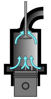
- Intake, induction or suction: The intake valves are open as a result of the cam lobe pressing down on the valve stem. The piston moves downward increasing the volume of the combustion chamber and allowing air to enter in the case of a CI engine or an air fuel mix in the case of SI engines that do not use direct injection. The air or air-fuel mixture is called the charge in any case.
- Compression: In this stroke, both valves are closed and the piston moves upward reducing the combustion chamber volume which reaches its minimum when the piston is at TDC. The piston performs work on the charge as it is being compressed; as a result its pressure, temperature and density increase; an approximation to this behavior is provided by the ideal gas law. Just before the piston reaches TDC, ignition begins. In the case of a SI engine, the spark plug receives a high voltage pulse that generates the spark which gives it its name and ignites the charge. In the case of a CI engine the fuel injector quickly injects fuel into the combustion chamber as a spray; the fuel ignites due to the high temperature.
- Power or working stroke: The pressure of the combustion gases pushes the piston downward, generating more work than it required to compress the charge. Complementary to the compression stroke, the combustion gases expand and as a result their temperature, pressure and density decreases. When the piston is near to BDC the exhaust valve opens. The combustion gases expand irreversibly due to the leftover pressure—in excess of back pressure, the gauge pressure on the exhaust port—; this is called the blowdown.
- Exhaust: The exhaust valve remains open while the piston moves upward expelling the combustion gases. For naturally aspirated engines a small part of the combustion gases may remain in the cylinder during normal operation because the piston does not close the combustion chamber completely; these gases dissolve in the next charge. At the end of this stroke, the exhaust valve closes, the intake valve opens, and the sequence repeats in the next cycle. The intake valve may open before the exhaust valve closes to allow better scavenging.
2-stroke engines
The defining characteristic of this kind of engine is that each piston completes a cycle every crankshaft revolution. The 4 processes of intake, compression, power and exhaust take place in only 2 strokes so that it is not possible to dedicate a stroke exclusively for each of them. Starting at TDC the cycle consist of:
- Power: While the piston is descending the combustion gases perform work on it—as in a 4-stroke engine—. The same thermodynamic considerations about the expansion apply.
- Scavenging: Around 75° of crankshaft rotation before BDC the exhaust valve or port opens, and blowdown occurs. Shortly thereafter the intake valve or transfer port opens. The incoming charge displaces the remaining combustion gases to the exhaust system and a part of the charge may enter the exhaust system as well. The piston reaches BDC and reverses direction. After the piston has traveled a short distance upwards into the cylinder the exhaust valve or port closes; shortly the intake valve or transfer port closes as well.
- Compression: With both intake and exhaust closed the piston continues moving upwards compressing the charge and performing a work on it. As in the case of a 4-stroke engine, ignition starts just before the piston reaches TDC and the same consideration on the thermodynamics of the compression on the charge.
While a 4-stroke engine uses the piston as a positive displacement pump to accomplish scavenging taking 2 of the 4 strokes, a 2-stroke engine uses the last part of the power stroke and the first part of the compression stroke for combined intake and exhaust. The work required to displace the charge and exhaust gases comes from either the crankcase or a separate blower. For scavenging, expulsion of burned gas and entry of fresh mix, two main approaches are described: Loop scavenging, and Uniflow scavenging, SAE news published in the 2010s that 'Loop Scavenging' is better under any circumstance than Uniflow Scavenging.[6]
Crankcase scavenged
Some SI engines are crankcase scavenged and do not use poppet valves. Instead the crankcase and the part of the cylinder below the piston is used as a pump. The intake port is connected to the crankcase through a reed valve or a rotary disk valve driven by the engine. For each cylinder a transfer port connects in one end to the crankcase and in the other end to the cylinder wall. The exhaust port is connected directly to the cylinder wall. The transfer and exhaust port are opened and closed by the piston. The reed valve opens when the crankcase pressure is slightly below intake pressure, to let it be filled with a new charge; this happens when the piston is moving upwards. When the piston is moving downwards the pressure in the crankcase increases and the reed valve closes promptly, then the charge in the crankcase is compressed. When the piston is moving upwards, it uncovers the exhaust port and the transfer port and the higher pressure of the charge in the crankcase makes it enter the cylinder through the transfer port, blowing the exhaust gases. Lubrication is accomplished by adding 2-stroke oil to the fuel in small ratios. Petroil refers to the mix of gasoline with the aforesaid oil. This kind of 2-stroke engines has a lower efficiency than comparable 4-strokes engines and release a more polluting exhaust gases for the following conditions:
- They use a total-loss lubrication system: all the lubricating oil is eventually burned along with the fuel.
- There are conflicting requirements for scavenging: On one side, enough fresh charge needs to be introduced in each cycle to displace almost all the combustion gases but introducing too much of it means that a part of it gets in the exhaust.
- They must use the transfer port(s) as a carefully designed and placed nozzle so that a gas current is created in a way that it sweeps the whole cylinder before reaching the exhaust port so as to expel the combustion gases, but minimize the amount of charge exhausted. 4-stroke engines have the benefit of forcibly expelling almost all of the combustion gases because during exhaust the combustion chamber is reduced to its minimum volume. In crankcase scavenged 2-stroke engines, exhaust and intake are performed mostly simultaneously and with the combustion chamber at its maximum volume.
The main advantage of 2-stroke engines of this type is mechanical simplicity and a higher power-to-weight ratio than their 4-stroke counterparts. Despite having twice as many power strokes per cycle, less than twice the power of a comparable 4-stroke engine is attainable in practice.
In the USA two stroke motorcycle and automobile engines were banned due to the pollution, although many thousands of lawn maintenance engines are in use.
Blower scavenged
Using a separate blower avoids many of the shortcomings of crankcase scavenging, at the expense of increased complexity which means a higher cost and an increase in maintenance requirement. An engine of this type uses ports or valves for intake and valves for exhaust, except opposed piston engines, which may also use ports for exhaust. The blower is usually of the Roots-type but other types have been used too. This design is commonplace in CI engines, and has been occasionally used in SI engines.
CI engines that use a blower typically use uniflow scavenging. In this design the cylinder wall contains several intake ports placed uniformly spaced along the circumference just above the position that the piston crown reaches when at BDC. An exhaust valve or several like that of 4-stroke engines is used. The final part of the intake manifold is an air sleeve which feeds the intake ports. The intake ports are placed at an horizontal angle to the cylinder wall (I.e: they are in plane of the piston crown) to give a swirl to the incoming charge to improve combustion. The largest reciprocating IC are low speed CI engines of this type; they are used for marine propulsion (see marine diesel engine) or electric power generation and achieve the highest thermal efficiencies among internal combustion engines of any kind. Some Diesel-electric locomotive engines operate on the 2-stroke cycle. The most powerful of them have a brake power of around 4.5 MW or 6,000 HP. The EMD SD90MAC class of locomotives use a 2-stroke engine. The comparable class GE AC6000CW whose prime mover has almost the same brake power uses a 4-stroke engine.
An example of this type of engine is the Wärtsilä-Sulzer RTA96-C turbocharged 2-stroke Diesel, used in large container ships. It is the most efficient and powerful internal combustion engine in the world with a thermal efficiency over 50%.[9][10][11][12] For comparison, the most efficient small four-stroke engines are around 43% thermally-efficient (SAE 900648); size is an advantage for efficiency due to the increase in the ratio of volume to surface area.
See the external links for a in-cylinder combustion video in a 2-stroke, optically accessible motorcycle engine.
Historical design
Dugald Clerk developed the first two cycle engine in 1879. It used a separate cylinder which functioned as a pump in order to transfer the fuel mixture to the cylinder.[6]
In 1899 John Day simplified Clerk's design into the type of 2 cycle engine that is very widely used today.[13] Day cycle engines are crankcase scavenged and port timed. The crankcase and the part of the cylinder below the exhaust port is used as a pump. The operation of the Day cycle engine begins when the crankshaft is turned so that the piston moves from BDC upward (toward the head) creating a vacuum in the crankcase/cylinder area. The carburetor then feeds the fuel mixture into the crankcase through a reed valve or a rotary disk valve (driven by the engine). There are cast in ducts from the crankcase to the port in the cylinder to provide for intake and another from the exhausst port to the exhaust pipe. The height of the port in relationship to the length of the cylinder is called the "port timing."
On the first upstroke of the engine there would be no fuel inducted into the cylinder as the crankcase was empty. On the downstroke the piston now compresses the fuel mix, which has lubricated the piston in the cylinder and the bearings due to the fuel mix having oil added to it. As the piston moves downward is first uncovers the exhaust, but on the first stroke there is no burnt fuel to exhaust. As the piston moves downward further, it uncovers the intake port which has a duct that runs to the crankcase. Since the fuel mix in the crankcase is under pressure the mix moves through the duct and into the cylinder.
Because there is no obstruction in the cylinder of the fuel to move directly out of the exhaust port prior to the piston rising far enough to close the port, early engines used a high domed piston to slow down the flow of fuel. Later the fuel was "resonated" back into the cylinder using an expansion chamber design. When the piston rose close to TDC a spark ignites the fuel. As the piston is driven downward with power it first uncovers the exhaust port where the burned fuel is expelled under high pressure and then the intake port where the process has been completed and will keep repeating.
Later engines used a type of porting devised by the Deutz company to improve performance. It was called the Schnurle Reverse Flow system. DKW licensed this design for all their motorcycles. Their DKW RT 125 was one of the first motor vehicles to achieve over 100 mpg as a result.[14]
Ignition
Internal combustion engines require ignition of the mixture, either by spark ignition (SI) or compression ignition (CI). Before the invention of reliable electrical methods, hot tube and flame methods were used. Experimental engines with laser ignition have been built.[15]
Spark ignition process

The spark ignition engine was a refinement of the early engines which used Hot Tube ignition. When Bosch developed the magneto it became the primary system for producing electricity to energize a spark plug.[16] Many small engines still use magneto ignition. Small engines are started by hand cranking using a recoil starter or hand crank . Prior to Charles F. Kettering of Delco's development of the automotive starter all gasoline engined automobiles used a hand crank.[17]
Larger engines typically power their starting motors and Ignition systems using the electrical energy stored in a lead–acid battery. The battery's charged state is maintained by an automotive alternator or (previously) a generator which uses engine power to create electrical energy storage.
The battery supplies electrical power for starting when the engine has a starting motor system, and supplies electrical power when the engine is off. The battery also supplies electrical power during rare run conditions where the alternator cannot maintain more than 13.8 volts (for a common 12V automotive electrical system). As alternator voltage falls below 13.8 volts, the lead-acid storage battery increasingly picks up electrical load. During virtually all running conditions, including normal idle conditions, the alternator supplies primary electrical power.
Some systems disable alternator field (rotor) power during wide open throttle conditions. Disabling the field reduces alternator pulley mechanical loading to nearly zero, maximizing crankshaft power. In this case the battery supplies all primary electrical power.
Gasoline engines take in a mixture of air and gasoline and compress it by the movement of the piston from bottom dead center to top dead center when the fuel is at maximum compression. The reduction in the size of the swept area of the cylinder and taking into account the volume of the combustion chamber is described by a ratio. Early engines had compression ratios of 6 to 1. As compression ratios were increased the efficiency of the engine increased as well.
With early induction and ignition systems the compression ratios had to be kept low. With advances in fuel technology and combustion management high performance engines can run reliably at 12:1 ratio. With low octane fuel a problem would occur as the compression ratio increased as the fuel was igniting due to the rise in temperature that resulted. Charles Kettering developed a lead additive which allowed higher compression ratios.
The fuel mixture is ignited at difference progressions of the piston in the cylinder. At low rpm the spark is timed to occur close to the piston achieving top dead center. In order to produce more power, as rpm rises the spark is advanced sooner during piston movement. The spark occurs while the fuel is still being compressed progressively more as rpm rises.[18]
The necessary high voltage, typically 10,000 volts, is supplied by an induction coil or transformer. The induction coil is a fly-back system, using interruption of electrical primary system current through some type of synchronized interrupter. The interrupter can be either contact points or a power transistor. The problem with this type of ignition is that as RPM increases the available of electrical energy decreases. This is especially as problem since the amount of energy needed to ignite a more dense fuel mixture is higher. The result was often a high rpm misfire.
Capacitor discharge ignition was developed. It produces a rising voltage that is sent to the spark plug. CD system voltages can reach 60,000 volts.[19] CD ignitions use step-up transformers. The step-up transformer uses energy stored in a capacitance to generate electric spark. With either system, a mechanical or electrical control system provides a carefully timed high-voltage to the proper cylinder. This spark, via the spark plug, ignites the air-fuel mixture in the engine's cylinders.
While gasoline internal combustion engines are much easier to start in cold weather than diesel engines, they can still have cold weather starting problems under extreme conditions. For years the solution was to park the car in heated areas. In some parts of the world the oil was actually drained and heated over night and returned to the engine for cold starts. In the early 1950s the gasoline Gasifier unit was developed, where, on cold weather starts, raw gasoline was diverted to the unit where part of the fuel was burned causing the other part to become a hot vapor sent directly to the intake valve manifold. This unit was quite popular until electric engine block heaters became standard on gasoline engines sold in cold climates.[20]
Compression ignition process
Diesel, PPC (Partially premixed combustion) and HCCI (Homogeneous charge compression ignition) engines, rely solely on heat and pressure created by the engine in its compression process for ignition. The compression level that occurs is usually twice or more than a gasoline engine. Diesel engines take in air only, and shortly before peak compression, spray a small quantity of diesel fuel into the cylinder via a fuel injector that allows the fuel to instantly ignite. HCCI type engines take in both air and fuel, but continue to rely on an unaided auto-combustion process, due to higher pressures and heat. This is also why diesel and HCCI engines are more susceptible to cold-starting issues, although they run just as well in cold weather once started. Light duty diesel engines with indirect injection in automobiles and light trucks employ glowplugs (or other pre-heating: see Cummins ISB#6BT) that pre-heat the combustion chamber just before starting to reduce no-start conditions in cold weather. Most diesels also have a battery and charging system; nevertheless, this system is secondary and is added by manufacturers as a luxury for the ease of starting, turning fuel on and off (which can also be done via a switch or mechanical apparatus), and for running auxiliary electrical components and accessories. Most new engines rely on electrical and electronic engine control units (ECU) that also adjust the combustion process to increase efficiency and reduce emissions.
Lubrication
.jpg)
| Wikimedia Commons has media related to Internal combustion piston engine lubrication systems. |
Surfaces in contact and relative motion to other surfaces require lubrication to reduce wear, noise and increase efficiency by reducing the power wasting in overcoming friction, or to make the mechanism work at all. At the very least, an engine requires lubrication in the following parts:
- Between pistons and cylinders
- Small bearings
- Big end bearings
- Main bearings
- Valve gear (The following elements may not be present):
- Tappets
- Rocker arms
- Pushrods
- Timing chain or gears. Toothed belts do not require lubrication.
In 2-stroke crankcase scavenged engines, the interior of the crankcase, and therefore the crankshaft, connecting rod and bottom of the pistons are sprayed by the 2-stroke oil in the air-fuel-oil mixture which is then burned along with the fuel. The valve train may be contained in a compartment flooded with lubricant so that no oil pump is required.
In a splash lubrication system no oil pump is used. Instead the crankshaft dips into the oil in the sump and due to its high speed, it splashes the crankshaft, connecting rods and bottom of the pistons. The connecting rod big end caps may have an attached scoop to enhance this effect. The valve train may also be sealed in a flooded compartment, or open to the crankshaft in a way that it receives splashed oil and allows it to drain back to the sump. Splash lubrication is common for small 4-stroke engines.
In a forced (also called pressurized) lubrication system, lubrication is accomplished in a closed loop which carries motor oil to the surfaces serviced by the system and then returns the oil to a reservoir. The auxiliary equipment of an engine is typically not serviced by this loop; for instance, an alternator may use ball bearings sealed with its lubricant. The reservoir for the oil is usually the sump, and when this is the case, it is called a wet sump system. When there is a different oil reservoir the crankcase still catches it, but it is continuously drained by a dedicated pump; this is called a dry sump system.
On its bottom, the sump contains an oil intake covered by a mesh filter which is connected to an oil pump then to an oil filter outside the crankcase, from there it is diverted to the crankshaft main bearings and valve train. The crankcase contains at least one oil gallery (a conduit inside a crankcase wall) to which oil is introduced from the oil filter. The main bearings contain a groove through all or half its circumference; the oil enters to these grooves from channels connected to the oil gallery. The crankshaft has drillings which take oil from these grooves and deliver it to the big end bearings. All big end bearings are lubricated this way. A single main bearing may provide oil for 0, 1 or 2 big end bearings. A similar system may be used to lubricate the piston, its gudgeon pin and the small end of its connecting rod; in this system, the connecting rod big end has a groove around the crankshaft and a drilling connected to the groove which distributes oil from there to the bottom of the piston and from then to the cylinder.
Other systems are also used to lubricate the cylinder and piston. The connecting rod may have a nozzle to throw an oil jet to the cylinder and bottom of the piston. That nozzle is in movement relative to the cylinder it lubricates, but always pointed towards it or the corresponding piston.
Typically a forced lubrication systems have a lubricant flow higher than what is required to lubricate satisfactorily, in order to assist with cooling. Specifically, the lubricant system helps to move heat from the hot engine parts to the cooling liquid (in water-cooled engines) or fins (in air-cooled engines) which then transfer it to the environment. The lubricant must be designed to be chemically stable and maintain suitable viscosities within the temperature range it encounters in the engine.
Cylinder configuration
Common cylinder configurations include the straight or inline configuration, the more compact V configuration, and the wider but smoother flat or boxer configuration. Aircraft engines can also adopt a radial configuration, which allows more effective cooling. More unusual configurations such as the H, U, X, and W have also been used.
Multiple cylinder engines have their valve train and crankshaft configured so that pistons are at different parts of their cycle. It is desirable to have the piston's cycles uniformly spaced (this is called even firing) especially in forced induction engines; this reduces torque pulsations[21] and makes inline engines with more than 3 cylinders statically balanced in its primary forces. However, some engine configurations require odd firing to achieve better balance than what is possible with even firing. For instance, a 4-stroke I2 engine has better balance when the angle between the crankpins is 180° because the pistons move in opposite directions and inertial forces partially cancel, but this gives an odd firing pattern where one cylinder fires 180° of crankshaft rotation after the other, then no cylinder fires for 540°. With an even firing pattern the pistons would move in unison and the associated forces would add.
Multiple crankshaft configurations do not necessarily need a cylinder head at all because they can instead have a piston at each end of the cylinder called an opposed piston design. Because fuel inlets and outlets are positioned at opposed ends of the cylinder, one can achieve uniflow scavenging, which, as in the four-stroke engine is efficient over a wide range of engine speeds. Thermal efficiency is improved because of a lack of cylinder heads. This design was used in the Junkers Jumo 205 diesel aircraft engine, using two crankshafts at either end of a single bank of cylinders, and most remarkably in the Napier Deltic diesel engines. These used three crankshafts to serve three banks of double-ended cylinders arranged in an equilateral triangle with the crankshafts at the corners. It was also used in single-bank locomotive engines, and is still used in marine propulsion engines and marine auxiliary generators.
Diesel cycle

Most truck and automotive diesel engines use a cycle reminiscent of a four-stroke cycle, but with a compression heating ignition system, rather than needing a separate ignition system. This variation is called the diesel cycle. In the diesel cycle, diesel fuel is injected directly into the cylinder so that combustion occurs at constant pressure, as the piston moves.
Otto cycle
Otto cycle is the typical cycle for most of the cars internal combustion engines, that work using gasoline as a fuel. Otto cycle is exactly the same one that was described for the four-stroke engine. It consists of the same major steps: Intake, compression, ignition, expansion and exhaust.
Five-stroke engine
In 1879, Nikolaus Otto manufactured and sold a double expansion engine (the double and triple expansion principles had ample usage in steam engines), with two small cylinders at both sides of a low-pressure larger cylinder, where a second expansion of exhaust stroke gas took place; the owner returned it, alleging poor performance. In 1906, the concept was incorporated in a car built by EHV (Eisenhuth Horseless Vehicle Company) CT, USA;[22] and in the 21st century Ilmor designed and successfully tested a 5-stroke double expansion internal combustion engine, with high power output and low SFC (Specific Fuel Consumption).[23]
Six-stroke engine
The six-stroke engine was invented in 1883. Four kinds of six-stroke use a regular piston in a regular cylinder (Griffin six-stroke, Bajulaz six-stroke, Velozeta six-stroke and Crower six-stroke), firing every three crankshaft revolutions. The systems capture the wasted heat of the four-stroke Otto cycle with an injection of air or water.
The Beare Head and "piston charger" engines operate as opposed-piston engines, two pistons in a single cylinder, firing every two revolutions rather more like a regular four-stroke.
Other cycles
The very first internal combustion engines did not compress the mixture. The first part of the piston downstroke drew in a fuel-air mixture, then the inlet valve closed and, in the remainder of the down-stroke, the fuel-air mixture fired. The exhaust valve opened for the piston upstroke. These attempts at imitating the principle of a steam engine were very inefficient. There are a number of variations of these cycles, most notably the Atkinson and Miller cycles. The diesel cycle is somewhat different.
Split-cycle engines separate the four strokes of intake, compression, combustion and exhaust into two separate but paired cylinders. The first cylinder is used for intake and compression. The compressed air is then transferred through a crossover passage from the compression cylinder into the second cylinder, where combustion and exhaust occur. A split-cycle engine is really an air compressor on one side with a combustion chamber on the other.
Previous split-cycle engines have had two major problems—poor breathing (volumetric efficiency) and low thermal efficiency. However, new designs are being introduced that seek to address these problems.
The Scuderi Engine addresses the breathing problem by reducing the clearance between the piston and the cylinder head through various turbo charging techniques. The Scuderi design requires the use of outwardly opening valves that enable the piston to move very close to the cylinder head without the interference of the valves. Scuderi addresses the low thermal efficiency via firing after top dead centre (ATDC).
Firing ATDC can be accomplished by using high-pressure air in the transfer passage to create sonic flow and high turbulence in the power cylinder.
Combustion turbines
Jet engine
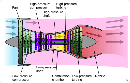
Jet engines use a number of rows of fan blades to compress air which then enters a combustor where it is mixed with fuel (typically JP fuel) and then ignited. The burning of the fuel raises the temperature of the air which is then exhausted out of the engine creating thrust. A modern turbofan engine can operate at as high as 48% efficiency.[24]
There are six sections to a Fan Jet engine:
- Fan
- Compressor
- Combustor
- Turbine
- Mixer
- Nozzle[25]
Gas turbines
A gas turbine compresses air and uses it to turn a turbine. It is essentially a jet engine which directs its output to a shaft. There are three stages to a turbine: 1) air is drawn through a compressor where the temperature rises due to compression, 2) fuel is added in the combuster, and 3) hot air is exhausted through turbine blades which rotate a shaft connected to the compressor.
A gas turbine is a rotary machine similar in principle to a steam turbine and it consists of three main components: a compressor, a combustion chamber, and a turbine. The air, after being compressed in the compressor, is heated by burning fuel in it. The heated air and the products of combustion expand in a turbine, producing work output. About ⅔ of the work drives the compressor: the rest (about ⅓) is available as useful work output.[26]
Gas Turbines are among the most efficient internal combustion engines. The General Electric 7HA and 9HA turbine combined cycle electrical plants are rated at over 61% efficiency.[27]
Brayton cycle
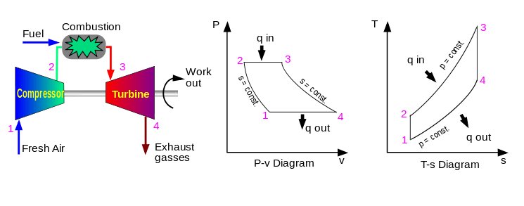
A gas turbine is a rotary machine somewhat similar in principle to a steam turbine. It consists of three main components: compressor, combustion chamber, and turbine. The air is compressed by the compressor where a temperature rise occurs. The compressed air is further heated by combustion of injected fuel in the combustion chamber which expands the air. This energy rotates the turbine which powers the compressor via a mechanical coupling. The hot gases are then exhausted to provide thrust.
Gas turbine cycle engines employ a continuous combustion system where compression, combustion, and expansion occur simultaneously at different places in the engine—giving continuous power. Notably, the combustion takes place at constant pressure, rather than with the Otto cycle, constant volume.
Wankel engines

The Wankel engine (rotary engine) does not have piston strokes. It operates with the same separation of phases as the four-stroke engine with the phases taking place in separate locations in the engine. In thermodynamic terms it follows the Otto engine cycle, so may be thought of as a "four-phase" engine. While it is true that three power strokes typically occur per rotor revolution, due to the 3:1 revolution ratio of the rotor to the eccentric shaft, only one power stroke per shaft revolution actually occurs. The drive (eccentric) shaft rotates once during every power stroke instead of twice (crankshaft), as in the Otto cycle, giving it a greater power-to-weight ratio than piston engines. This type of engine was most notably used in the Mazda RX-8, the earlier RX-7, and other vehicle models. The engine is also use in unmanned aerial vehicles, where the small size and weight and the high power-to-weight ratio are advantages.
Forced induction
Forced induction is the process of delivering compressed air to the intake of an internal combustion engine. A forced induction engine uses a gas compressor to increase the pressure, temperature and density of the air. An engine without forced induction is considered a naturally aspirated engine.
Forced induction is used in the automotive and aviation industry to increase engine power and efficiency. It particularly helps aviation engines, as they need to operate at high altitude.
Forced induction is achieved by a supercharger, where the compressor is directly powered from the engine shaft or, in the turbocharger, from a turbine powered by the engine exhaust.
Fuels and oxidizers
All internal combustion engines depend on combustion of a chemical fuel, typically with oxygen from the air (though it is possible to inject nitrous oxide to do more of the same thing and gain a power boost). The combustion process typically results in the production of a great quantity of heat, as well as the production of steam and carbon dioxide and other chemicals at very high temperature; the temperature reached is determined by the chemical make up of the fuel and oxidisers (see stoichiometry), as well as by the compression and other factors.
Fuels
The most common modern fuels are made up of hydrocarbons and are derived mostly from fossil fuels (petroleum). Fossil fuels include diesel fuel, gasoline and petroleum gas, and the rarer use of propane. Except for the fuel delivery components, most internal combustion engines that are designed for gasoline use can run on natural gas or liquefied petroleum gases without major modifications. Large diesels can run with air mixed with gases and a pilot diesel fuel ignition injection. Liquid and gaseous biofuels, such as ethanol and biodiesel (a form of diesel fuel that is produced from crops that yield triglycerides such as soybean oil), can also be used. Engines with appropriate modifications can also run on hydrogen gas, wood gas, or charcoal gas, as well as from so-called producer gas made from other convenient biomass. Experiments have also been conducted using powdered solid fuels, such as the magnesium injection cycle.
Presently, fuels used include:
- Petroleum:
- Petroleum spirit (North American term: gasoline, British term: petrol)
- Petroleum diesel.
- Autogas (liquified petroleum gas).
- Compressed natural gas.
- Jet fuel (aviation fuel)
- Residual fuel
- Coal:
- Gasoline can be made from carbon (coal) using the Fischer-Tropsch process
- Diesel fuel can be made from carbon using the Fischer-Tropsch process
- Biofuels and vegetable oils:
- Peanut oil and other vegetable oils.
- Woodgas, from an onboard wood gasifier using solid wood as a fuel
- Biofuels:
- Biobutanol (replaces gasoline).
- Biodiesel (replaces petrodiesel).
- Dimethyl Ether (replaces petrodiesel).
- Bioethanol and Biomethanol (wood alcohol) and other biofuels (see Flexible-fuel vehicle).
- Biogas
- Hydrogen (mainly spacecraft rocket engines)
Even fluidized metal powders and explosives have seen some use. Engines that use gases for fuel are called gas engines and those that use liquid hydrocarbons are called oil engines; however, gasoline engines are also often colloquially referred to as, "gas engines" ("petrol engines" outside North America).
The main limitations on fuels are that it must be easily transportable through the fuel system to the combustion chamber, and that the fuel releases sufficient energy in the form of heat upon combustion to make practical use of the engine.
Diesel engines are generally heavier, noisier, and more powerful at lower speeds than gasoline engines. They are also more fuel-efficient in most circumstances and are used in heavy road vehicles, some automobiles (increasingly so for their increased fuel efficiency over gasoline engines), ships, railway locomotives, and light aircraft. Gasoline engines are used in most other road vehicles including most cars, motorcycles, and mopeds. Note that in Europe, sophisticated diesel-engined cars have taken over about 45% of the market since the 1990s. There are also engines that run on hydrogen, methanol, ethanol, liquefied petroleum gas (LPG), biodiesel, paraffin and tractor vaporizing oil (TVO).
Hydrogen
Hydrogen could eventually replace conventional fossil fuels in traditional internal combustion engines. Alternatively fuel cell technology may come to deliver its promise and the use of the internal combustion engines could even be phased out.
Although there are multiple ways of producing free hydrogen, those methods require converting combustible molecules into hydrogen or consuming electric energy. Unless that electricity is produced from a renewable source—and is not required for other purposes— hydrogen does not solve any energy crisis. In many situations the disadvantage of hydrogen, relative to carbon fuels, is its storage. Liquid hydrogen has extremely low density (14 times lower than water) and requires extensive insulation—whilst gaseous hydrogen requires heavy tankage. Even when liquefied, hydrogen has a higher specific energy but the volumetric energetic storage is still roughly five times lower than gasoline. However, the energy density of hydrogen is considerably higher than that of electric batteries, making it a serious contender as an energy carrier to replace fossil fuels. The 'Hydrogen on Demand' process (see direct borohydride fuel cell) creates hydrogen as needed, but has other issues, such as the high price of the sodium borohydride that is the raw material.
Oxidizers

Since air is plentiful at the surface of the earth, the oxidizer is typically atmospheric oxygen, which has the advantage of not being stored within the vehicle. This increases the power-to-weight and power-to-volume ratios. Other materials are used for special purposes, often to increase power output or to allow operation under water or in space.
- Compressed air has been commonly used in torpedoes.
- Compressed oxygen, as well as some compressed air, was used in the Japanese Type 93 torpedo. Some submarines carry pure oxygen. Rockets very often use liquid oxygen.
- Nitromethane is added to some racing and model fuels to increase power and control combustion.
- Nitrous oxide has been used—with extra gasoline—in tactical aircraft, and in specially equipped cars to allow short bursts of added power from engines that otherwise run on gasoline and air. It is also used in the Burt Rutan rocket spacecraft.
- Hydrogen peroxide power was under development for German World War II submarines. It may have been used in some non-nuclear submarines, and was used on some rocket engines (notably the Black Arrow and the Me-163 rocket plane).
- Other chemicals such as chlorine or fluorine have been used experimentally, but have not been found practical.
Cooling
Cooling is required to remove excessive heat — over heating can cause engine failure, usually from wear(due to heat-induced failure of lubrication), cracking or warping. Two most common forms of engine cooling are air-cooled and water-cooled. Most modern automotive engines are both water and air-cooled, as the water/liquid-coolant is carried to air-cooled fins and/or fans, whereas larger engines may be singularly water-cooled as they are stationary and have a constant supply of water through water-mains or fresh-water, while most power tool engines and other small engines are air-cooled. Some engines (air or water-cooled) also have an oil cooler. In some engines, especially for turbine engine blade cooling and liquid rocket engine cooling, fuel is used as a coolant, as it is simultaneously preheated before injecting it into a combustion chamber.
Starting
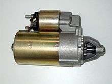
Internal Combustion engines must have their cycles started. In reciprocating engines this is accomplished by turning the crankshaft (Wankel Rotor Shaft) which induces the cycles of intake, compression, combustion, and exhaust. The first engines were started with a turn of their flywheels, while the first vehicle (the Daimler Reitwagen) was started with a hand crank. All ICE engined automobiles were started with hand cranks until Charles Kettering developed the electric starter for automobiles.[28]
The most often found methods of starting ICE today is with an electric motor. As diesel engines have become larger another method has come into use as well, that is Air Starters.[29]
Another method of starting is to use compressed air that is pumped into some cylinders of an engine to start it turning.
With two wheeled vehicles their engines may be started in four ways:
- By pedaling, as on a bicycle
- By pushing the vehicle and then engaging the clutch (Run and Bump Starting)
- By kicking downward on a single pedal, known as Kick Starting
- Electric Starting
There are also starters where a spring is compressed by a crank motion and then used to start an engine. Small engines use a pull rope mechanism called recoil starting as the rope returns to storage after it has been pulled fully out to start the engine.
Turbine engines are frequently started by electric motor, or by air.
Measures of engine performance
Engine types vary greatly in a number of different ways:
- energy efficiency
- fuel/propellant consumption (brake specific fuel consumption for shaft engines, thrust specific fuel consumption for jet engines)
- power-to-weight ratio
- thrust to weight ratio
- Torque curves (for shaft engines) thrust lapse (jet engines)
- Compression ratio for piston engines, overall pressure ratio for jet engines and gas turbines
Energy efficiency
Once ignited and burnt, the combustion products—hot gases—have more available thermal energy than the original compressed fuel-air mixture (which had higher chemical energy). The available energy is manifested as high temperature and pressure that can be translated into work by the engine. In a reciprocating engine, the high-pressure gases inside the cylinders drive the engine's pistons.
Once the available energy has been removed, the remaining hot gases are vented (often by opening a valve or exposing the exhaust outlet) and this allows the piston to return to its previous position (top dead center, or TDC). The piston can then proceed to the next phase of its cycle, which varies between engines. Any heat that is not translated into work is normally considered a waste product and is removed from the engine either by an air or liquid cooling system.
Internal combustion engines are heat engines, and as such their theoretical efficiency can be approximated by idealized thermodynamic cycles. The thermal efficiency of a theoretical cycle cannot exceed that of the Carnot cycle, whose efficiency is determined by the difference between the lower and upper operating temperatures of the engine. The upper operating temperature of an engine is limited by two main factors; the thermal operating limits of the materials, and the auto-ignition resistance of the fuel. All metals and alloys have a thermal operating limit, and there is significant research into ceramic materials that can be made with greater thermal stability and desirable structural properties. Higher thermal stability allows for a greater temperature difference between the lower (ambient) and upper operating temperatures, hence greater thermodynamic efficiency. Also, as the cylinder temperature rises, the engine becomes more prone to auto-ignition. This is caused when the cylinder temperature nears the flash point of the charge. At this point, ignition can spontaneously occur before the spark plug fires, causing excessive cylinder pressures. Auto-ignition can be mitigated by using fuels with high auto-ignition resistance (octane rating), however it still puts an upper bound on the allowable peak cylinder temperature.
The thermodynamic limits assume that the engine is operating under ideal conditions: a frictionless world, ideal gases, perfect insulators, and operation for infinite time. Real world applications introduce complexities that reduce efficiency. For example, a real engine runs best at a specific load, termed its power band. The engine in a car cruising on a highway is usually operating significantly below its ideal load, because it is designed for the higher loads required for rapid acceleration. In addition, factors such as wind resistance reduce overall system efficiency. Engine fuel economy is measured in miles per gallon or in liters per 100 kilometres. The volume of hydrocarbon assumes a standard energy content.
Most iron engines have a thermodynamic limit of 37%. Even when aided with turbochargers and stock efficiency aids, most engines retain an average efficiency of about 18%-20 %.[30] The latest technologies in Formula One engines have seen a boost in thermal efficiency to almost 47%.[31] Rocket engine efficiencies are much better, up to 70%, because they operate at very high temperatures and pressures and can have very high expansion ratios.[32] Electric motors are better still, at around 85 -90 % efficiency or more, but they rely on an external power source (often another heat engine at a power plant subject to similar thermodynamic efficiency limits). However large stationary power plant turbines are typically significantly more efficient and cleaner than small mobile combustion engines in vehicles.
There are many inventions aimed at increasing the efficiency of IC engines. In general, practical engines are always compromised by trade-offs between different properties such as efficiency, weight, power, heat, response, exhaust emissions, or noise. Sometimes economy also plays a role in not only the cost of manufacturing the engine itself, but also manufacturing and distributing the fuel. Increasing the engine's efficiency brings better fuel economy but only if the fuel cost per energy content is the same.
Measures of fuel efficiency and propellant efficiency
For stationary and shaft engines including propeller engines, fuel consumption is measured by calculating the brake specific fuel consumption, which measures the mass flow rate of fuel consumption divided by the power produced.
For internal combustion engines in the form of jet engines, the power output varies drastically with airspeed and a less variable measure is used: thrust specific fuel consumption (TSFC), which is the mass of propellant needed to generate impulses that is measured in either pound force-hour or the grams of propellant needed to generate an impulse that measures one kilonewton-second.
For rockets, TSFC can be used, but typically other equivalent measures are traditionally used, such as specific impulse and effective exhaust velocity.
Air and noise pollution
Air pollution
Internal combustion engines such as reciprocating internal combustion engines produce air pollution emissions, due to incomplete combustion of carbonaceous fuel. The main derivatives of the process are carbon dioxide CO
2, water and some soot — also called particulate matter (PM). The effects of inhaling particulate matter have been studied in humans and animals and include asthma, lung cancer, cardiovascular issues, and premature death. There are, however, some additional products of the combustion process that include nitrogen oxides and sulfur and some uncombusted hydrocarbons, depending on the operating conditions and the fuel-air ratio.
Not all of the fuel is completely consumed by the combustion process; a small amount of fuel is present after combustion, and some of it reacts to form oxygenates, such as formaldehyde or acetaldehyde, or hydrocarbons not originally present in the input fuel mixture. Incomplete combustion usually results from insufficient oxygen to achieve the perfect stoichiometric ratio. The flame is "quenched" by the relatively cool cylinder walls, leaving behind unreacted fuel that is expelled with the exhaust. When running at lower speeds, quenching is commonly observed in diesel (compression ignition) engines that run on natural gas. Quenching reduces efficiency and increases knocking, sometimes causing the engine to stall. Incomplete combustion also leads to the production of carbon monoxide (CO). Further chemicals released are benzene and 1,3-butadiene that are also hazardous air pollutants.
Increasing the amount of air in the engine reduces emissions of incomplete combustion products, but also promotes reaction between oxygen and nitrogen in the air to produce nitrogen oxides (NOx). NOx is hazardous to both plant and animal health, and leads to the production of ozone (O3). Ozone is not emitted directly; rather, it is a secondary air pollutant, produced in the atmosphere by the reaction of NOx and volatile organic compounds in the presence of sunlight. Ground-level ozone is harmful to human health and the environment. Though the same chemical substance, ground-level ozone should not be confused with stratospheric ozone, or the ozone layer, which protects the earth from harmful ultraviolet rays.
Carbon fuels contain sulfur and impurities that eventually produce sulfur monoxides (SO) and sulfur dioxide (SO2) in the exhaust, which promotes acid rain.
In the United States, nitrogen oxides, PM, carbon monoxide, sulphur dioxide, and ozone, are regulated as criteria air pollutants under the Clean Air Act to levels where human health and welfare are protected. Other pollutants, such as benzene and 1,3-butadiene, are regulated as hazardous air pollutants whose emissions must be lowered as much as possible depending on technological and practical considerations.
NOx, carbon monoxide and other pollutants are frequently controlled via exhaust gas recirculation which returns some of the exhaust back into the engine intake, and catalytic converters, which convert exhaust chemicals to harmless chemicals.
Non-road engines
The emission standards used by many countries have special requirements for non-road engines which are used by equipment and vehicles that are not operated on the public roadways. The standards are separated from the road vehicles.[33]
Noise pollution
Significant contributions to noise pollution are made by internal combustion engines. Automobile and truck traffic operating on highways and street systems produce noise, as do aircraft flights due to jet noise, particularly supersonic-capable aircraft. Rocket engines create the most intense noise.
Idling
Internal combustion engines continue to consume fuel and emit pollutants when idling so it is desirable to keep periods of idling to a minimum. Many bus companies now instruct drivers to switch off the engine when the bus is waiting at a terminal.
In England, the Road Traffic Vehicle Emissions Fixed Penalty Regulations 2002 (Statutory Instrument 2002 No. 1808) [34] introduced the concept of a "stationary idling offence". This means that a driver can be ordered "by an authorised person ... upon production of evidence of his authorisation, require him to stop the running of the engine of that vehicle" and a "person who fails to comply ... shall be guilty of an offence and be liable on summary conviction to a fine not exceeding level 3 on the standard scale". Only a few local authorities have implemented the regulations, one of them being Oxford City Council.[35]
See also
- Adiabatic flame temperature
- Air-fuel ratio
- Bore
- Component parts of internal combustion engines
- Crude oil engine - a two-stroke engine
- Deglazing (engine mechanics)
- Diesel engine
- Dieselisation
- Direct injection
- Dynamometer
- Electric vehicle
- Engine test stand - information about how to check an internal combustion engine
- External Combustion Engine
- Fossil fuels
- Gasoline direct injection
- Gas turbine
- Heat pump
- Hybrid vehicle
- Indirect injection
- Jet engine
- Magnesium injection cycle
- Piston engine
- Petrofuel
- Reciprocating engine
- Stroke
- Turbocharger
- Variable displacement
References
- 1 2 "History of Technology: Internal Combustion engines". Encyclopædia Britannica. Britannica.com. Retrieved 2012-03-20.
- 1 2 Pulkrabek, Willard W. (1997). Engineering Fundamentals of the Internal Combustion Engine. Prentice Hall. p. 2. ISBN 9780135708545.
- ↑ "World Wide Words: Engine and Motor". World Wide Words. 1998-12-27. Retrieved 2016-08-31.
- ↑ James, Fales. Technology Today and Tomorrow. p. 344.
- ↑ Armentrout, Patricia. Extreme Machines on Land. p. 8.
- 1 2 3 "Two Stroke Cycle Diesel Engine". First Hand Info. Retrieved 2016-09-01.
- ↑ Stone 1992, pp. 1-2.
- ↑ Nunney 2007, p. 5.
- ↑ Low Speed Engines, MAN Diesel.
- ↑ "CFX aids design of world's most efficient steam turbine" (PDF). Retrieved 2010-08-28.
- ↑ "New Benchmarks for Steam Turbine Efficiency - Power Engineering". Pepei.pennnet.com. 2010-08-24. Retrieved 2010-08-28.
- ↑ Takaishi, Tatsuo; Numata, Akira; Nakano, Ryouji; Sakaguchi, Katsuhiko (March 2008). "Approach to High Efficiency Diesel and Gas Engines" (PDF). Mitsubishi Heavy Industries Technical Review. 45 (1). Retrieved 2011-02-04.
- ↑ "Two Stroke Spark Ignition (S.I) Engine". First Hand Info. Retrieved 2016-09-01.
- ↑ "DKW RT 125/2H, 1954 > Models > History > AUDI AG". Audi. Retrieved 2016-09-01.
- ↑ "Laser sparks revolution in internal combustion engines". Physorg.com. 2011-04-20. Retrieved 2013-12-26.
- ↑ "The Early History of the Bosch Magneto Company in America". The Old Motor. 2014-12-19. Retrieved 2016-09-01.
- ↑ "Hand Cranking the Engine". Automobile in American Life and Society. University of Michigan-Dearborn. Retrieved 2016-09-01.
- ↑ "Spark Timing Myths Debunked - Spark Timing Myths Explained:: Application Notes". Innovate Motorsports. Retrieved 2006-09-01.
- ↑ "Electronic Ignition Overview". Jetav8r. Retrieved 2016-09-02.
- ↑ "Gasifier Aids Motor Starting Under Arctic Conditions". Popular Mechanics: 149. January 1953.
- ↑ Nunney 2007, p. 15.
- ↑ Suzuki, Takashi (1997). The Romance of Engines. SAE. pp. 87–94.
- ↑ "5-Stroke Concept Engine Design and Development". Ilmor Engineering. Retrieved 2015-12-18.
- ↑ "Aviation and the Global Atmosphere". Intergovernment Panel on Climate Change. Retrieved 2016-07-14.
- ↑ "Engines". US: NASA Glenn Research Center. 2014-06-12. Retrieved 2016-08-31.
- ↑ "How a Gas Turbine Works". General Electric Power Generation. General Electric. Retrieved 2016-07-14.
- ↑ "Air-cooled 7HA and 9HA designs rated at over 61% CC efficiency". Gasturbineworld. Retrieved 2016-07-14.
- ↑ "Cadillac's Electric Self Starter Turns 100" (Press release). US: General Motors. Retrieved 2016-09-02.
- ↑ "Ingersoll Rand Engine Starting - Turbine, Vane and Gas Air Starters". Ingersoll Rand. Retrieved 2016-09-05.
- ↑ "Improving IC Engine Efficiency". Courses.washington.edu. Retrieved 2010-08-28.
- ↑ "Turbulent times for Formula 1 engines result in unprecedented efficiency gains". Ars Technica. Retrieved 2016-05-20.
- ↑ Rocket propulsion elements 7th edition-George Sutton, Oscar Biblarz pg 37-38
- ↑ "2013 Global Sourcing Guide" (PDF). Diesel & Gas Turbine Publications. Retrieved 2013-12-26.
- ↑ "The Road Traffic (Vehicle Emissions) (Fixed Penalty) (England) Regulations 2002". 195.99.1.70. 2010-07-16. Retrieved 2010-08-28.
- ↑ "CITY DEVELOPMENT - Fees & Charges 2010-11" (PDF). Oxford City Council. November 2011. Retrieved 2011-02-04.
Bibliography
- Nunney, Malcom J. (2007). Light and Heavy Vehicle Technology (4th ed.). Elsevier Butterworth-Heinemann. ISBN 978-0-7506-8037-0.
- Stone, Richard (1992). Introduction to Internal Combustion Engines (2nd ed.). Macmillan. ISBN 0-333-55083-8.
- Anyebe, E.A (2009). Combustion Engine and Operations, Automobile Technology Handbook. 2.
- Singal, R. K. Internal Combustion Engines. New Delhi, India: Kataria Books. ISBN 978-93-5014-214-1.
- Ricardo, Harry (1931). The High-Speed Internal Combustion Engine.
- Patents:
- ES 156621
- ES 433850, Ubierna Laciana, "Perfeccionamientos en Motores de Explosion, con Cinco Tiem-Pos y Doble Expansion", published 1976-11-01
- ES 230551, Ortuno Garcia Jose, "Un Nuevo Motor de Explosion", published 1957-03-01
- ES 249247, Ortuno Garcia Jose, "Motor de Carreras Distintas", published 1959-09-01
Further reading
- Singer, Charles Joseph; Raper, Richard (1978). Charles, Singer; et al., eds. A History of Technology: The Internal Combustion Engine. Clarendon Press. pp. 157–176. ISBN 9780198581550.
- Setright, LJK (1975). Some unusual engines. London: The Institution of Mechanical Engineers. ISBN 0-85298-208-9.
- Suzuki, Takashi (1997). The Romance of Engines. US: Society of Automotive Engineers. ISBN 1-56091-911-6.
- Hardenberg, Horst O. (1999). The Middle Ages of the Internal Combustion Engine. US: Society of Automotive Engineers.
- Gunston, Bill (1999). Development of Piston Aero Engines. PSL. ISBN 978-1-85260-619-0.
External links
| Wikimedia Commons has media related to Internal combustion engines. |
- Combustion video - in-cylinder combustion in an optically accessible, 2-stroke engine
- Animated Engines - explains a variety of types
- Intro to Car Engines - Cut-away images and a good overview of the internal combustion engine
- Walter E. Lay Auto Lab - Research at The University of Michigan
- youtube - Animation of the components and built-up of a 4-cylinder engine
- youtube - Animation of the internal moving parts of a 4-cylinder engine
- Next generation engine technologies retrieved May 9, 2009
- MIT Overview - Present & Future Internal Combustion Engines: Performance, Efficiency, Emissions, and Fuels
- Engine Combustion Network - Open forum for international collaboration among experimental and computational researchers in engine combustion.
- Automakers Show Interest in an Unusual Engine Design
- How Car Engines Work
- A file on unusual engines
- Aircraft Engine Historical Society -AEHS