Water wheel


A water wheel is a machine for converting the energy of free-flowing or falling water into useful forms of power, often in a watermill. A water wheel consists of a large wooden or metal wheel, with a number of blades or buckets arranged on the outside rim forming the driving surface. Most commonly, the wheel is mounted vertically on a horizontal axle, but the tub or Norse wheel is mounted horizontally on a vertical shaft. Vertical wheels can transmit power either through the axle or via a ring gear and typically drive belts or gears; horizontal wheels usually directly drive their load.
Water wheels were still in commercial use well into the 20th century, but they are no longer in common use. Prior uses of water wheels include milling flour in gristmills and grinding wood into pulp for papermaking, but other uses include hammering wrought iron, machining, ore crushing and pounding fiber for use in the manufacture of cloth.
Some water wheels are fed by water from a mill pond, which is formed when a flowing stream is dammed. A channel for the water flowing to or from a water wheel is called a mill race (also spelled millrace) or simply a "race", and is customarily divided into sections. The race bringing water from the mill pond to the water wheel is a headrace; the one carrying water after it has left the wheel is commonly referred to as a tailrace.[1]
John Smeaton's scientific investigation of the water wheel led to significant increases in efficiency in the mid to late 18th century and supplying much needed power for the Industrial Revolution.[2][3]
Water wheels began being displaced by the smaller, less expensive and more efficient turbine, developed by Benoît Fourneyron, beginning with his first model in 1827.[3] Turbines are capable of handling high heads, or elevations, that exceed the capability of practical-sized waterwheels.
The main difficulty of water wheels is their dependence on flowing water, which limits where they can be located. Modern hydroelectric dams can be viewed as the descendants of the water wheel, as they too take advantage of the movement of water downhill.
History
The two main functions of water wheels were historically water-lifting for irrigation purposes and as a power source. In terms of power source, water wheels can be turned either by human or animal force or by the water current itself. Water wheels come in two basic designs, either equipped with a vertical or a horizontal axle. The latter type can be subdivided, depending on where the water hits the wheel paddles, into overshot, breastshot and undershot wheels.
Greco-Roman world
Engineers of the Hellenistic era Mediterranean region are credited with the development of the water wheel. Mediterranean engineers of the Hellenistic and Roman periods were also the first to use it for both irrigation and as a power source.[4] The technological breakthrough occurred in the technically advanced and scientifically minded Hellenistic period between the 3rd and 1st centuries BCE.[5] This is seen as an evolution of the paddle-driven water-lifting wheels that had appeared in ancient Egypt by the 4th century BCE.[6] According to John Peter Oleson, both the compartmented wheel and the hydraulic Noria appeared in Egypt by the 4th century BCE, with the Sakia being invented there a century later. This is supported by archeological finds at Faiyum, where the oldest archeological evidence of a water-wheel has been found, in the form of a Sakia dating back to the 3rd century BCE. A papyrus dating to the 2nd century BCE also found in Faiyum mentions a water wheel used for irrigation, a 2nd-century BC fresco found at Alexandria depicts a compartmented Sakia, and the writings of Callixenus of Rhodes mention the use of a Sakia in Ptolemaic Egypt during the reign of Ptolemy IV in the late 3rd century BC.[7]
Drainage wheels

The Romans used water wheels extensively in mining projects. Several such devices were described by Vitruvius. The one found during modern mining at the copper mines at Rio Tinto in Spain involved 16 such wheels stacked above one another so as to lift water about 80 feet (24 m) from the mine sump. Part of a similar wheel dated to about 90 CE, was found in the 1930s, at Dolaucothi, a Roman gold mine in south Wales.
Water mills
Taking indirect evidence into account from the work of the Greek technician Apollonius of Perge, the British historian of technology M.J.T. Lewis dates the appearance of the vertical-axle watermill to the early 3rd century BCE, and the horizontal-axle watermill to around 240 BC, with Byzantium and Alexandria as the assigned places of invention.[8] A watermill is reported by the Greek geographer Strabon (ca. 64 BCE–CE 24) to have existed sometime before 71 BCE in the palace of the Pontian king Mithradates VI Eupator, but its exact construction cannot be gleaned from the text (XII, 3, 30 C 556).[9]
The first clear description of a geared watermill is from the 1st-century BC Roman architect Vitruvius, who tells of the sakia gearing system as being applied to a watermill.[10] Vitruvius's account is particularly valuable in that it shows how the watermill came about, namely by the combination of the separate Greek inventions of the toothed gear and the water wheel into one effective mechanical system for harnessing water power.[11] Vitruvius's water wheel is described as being immersed with its lower end in the watercourse so that its paddles could be driven by the velocity of the running water (X, 5.2).[12]

About the same time, the overshot wheel appears for the first time in a poem by Antipater of Thessalonica, which praises it as a labour-saving device (IX, 418.4–6).[13] The motif is also taken up by Lucretius (ca. 99-55 BC) who likens the rotation of the water wheel to the motion of the stars on the firmament (V 516).[14] The third horizontal-axled type, the breastshot water wheel, comes into archaeological evidence by the late-2nd-century AD context in central Gaul.[15] Most excavated Roman watermills were equipped with one of these wheels which, although more complex to construct, were much more efficient than the vertical-axle water wheel.[16] In the 2nd century AD, Barbegal watermill complex a series of sixteen overshot wheels was fed by an artificial aqueduct, a proto-industrial grain factory which has been referred to as "the greatest known concentration of mechanical power in the ancient world".[17]
In Roman North Africa, several installations from around 300 AD were found where vertical-axle water wheels fitted with angled blades were installed at the bottom of a water-filled, circular shaft. The water from the mill-race which entered the pit tangentially created a swirling water column that made the fully submerged wheel act like true water turbines, the earliest known to date.[18]
Navigation
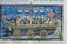
Apart from its use in milling and water-raising, ancient engineers applied the paddled water wheel for automatons and in navigation. Vitruvius (X 9.5-7) describes multi-geared paddle wheels working as a ship odometer, the earliest of its kind. The first mention of paddle wheels as a means of propulsion comes from the 4th–5th-century military treatise De Rebus Bellicis (chapter XVII), where the anonymous Roman author describes an ox-driven paddle-wheel warship.[19]
Early Medieval Europe
Ancient water-wheel technology continued unabated in the early medieval period where the appearance of new documentary genres such as legal codes, monastic charters, but also hagiography was accompanied with a sharp increase in references to watermills and wheels.[20]
The earliest vertical-wheel in a tide mill is from 6th-century Killoteran near Waterford, Ireland,[21] while the first known horizontal-wheel in such a type of mill is from the Irish Little Island (c. 630).[22] As for the use in a common Norse or Greek mill, the oldest known horizontal-wheels were excavated in the Irish Ballykilleen, dating to c. 636.[22]
The earliest excavated water wheel driven by tidal power was the Nendrum Monastery mill in Northern Ireland which has been dated at 787A.D. although a possible earlier mill dates to 619A.D. Tide mills became common in estuaries with a good tidal range in both Europe and America generally using undershot wheels.

Cistercian monasteries, in particular, made extensive use of water wheels to power watermills of many kinds. An early example of a very large water wheel is the still extant wheel at the early 13th century Real Monasterio de Nuestra Senora de Rueda, a Cistercian monastery in the Aragon region of Spain. Grist mills (for corn) were undoubtedly the most common, but there were also sawmills, fulling mills and mills to fulfil many other labour-intensive tasks. The water wheel remained competitive with the steam engine well into the Industrial Revolution. At around the 8th to 10th century, a number of irrigation technologies were brought into Spain and thus introduced to Europe. One of those technologies is the Noria, which is basically a wheel fitted with buckets on the peripherals for lifting water. It is similar to the undershot water wheel mentioned later in this article. It allowed peasants to power watermills more efficiently. According to Thomas Glick's book, Irrigation and Society in Medieval Valencia, the Noria probably originated from somewhere in Persia. It has been used for centuries before the technology was brought into Spain by Arabs who had adopted it from the Romans. Thus the distribution of the Noria in the Iberian peninsula "conforms to the area of stabilized Islamic settlement".[23] This technology has a profound effect on the life of peasants. The Noria is relatively cheap to build. Thus it allowed peasants to cultivate land more efficiently in Europe. Together with the Spaniards, the technology then spread to North Africa and later to the New World in Mexico and South America following Spanish expansion.
Domesday inventory of English mills ca. 1086
The assembly convened by William of Normandy, commonly referred to as the “Domesday” or Doomsday survey, took an inventory of all potentially taxable property in England, which included over six thousand mills spread across three thousand different locations.[24]
Locations
The type of water wheel selected was dependent upon the location. Generally if only small volumes of water and high waterfalls were available a millwright would choose to use an overshot wheel. The decision was influenced by the fact that the buckets could catch and use even a small volume of water.[25] For large volumes of water with small waterfalls the undershot wheel would have been used, since it was more adapted to such conditions and cheaper to construct. So long as these water supplies were abundant the question of efficiency remained irrelevant. By the 18th century with increased demand for power coupled with limited water locales, an emphasis was made on efficiency scheme.[25]
Economic influence
By the 11th century there were parts of Europe where the exploitation of water was commonplace.[24] The water wheel is understood to have actively shaped and forever changed the outlook of Westerners. Europe began to transit from human and animal muscle labor towards mechanical labor with the advent of the water wheel. Medievalist Lynn White Jr. contended that the spread of inanimate power sources was eloquent testimony to the emergence of the West of a new attitude toward, power, work, nature, and above all else technology.[24]
Harnessing water-power enabled gains in agricultural productivity, food surpluses and the large scale urbanization starting in the 11th century. The usefulness of water power motivated European experiments with other power sources, such as wind and tidal mills.[26] Waterwheels influenced the construction of cities, more specifically canals. The techniques that developed during this early period such as stream jamming and the building of canals, put Europe on a hydraulically focused path, for instance water supply and irrigation technology was combined to modify supply power of the wheel.[27] Illustrating the extent to which there was a great degree of technological innovation that met the growing needs of the feudal state.
Applications of the water wheel in medieval Europe

The water mill was used for grinding grain, producing flour for bread, malt for beer, or coarse meal for porridge.[28] Hammermills used the wheel to operate hammers. One type was fulling mill, which was used for cloth making. The trip hammer was also used for making wrought iron and for working iron into useful shapes, an activity that was otherwise labour-intensive. The water wheel was also used in papermaking, beating material to a pulp. In the 13th century water mills used for hammering throughout Europe improved the productivity of early steel manufacturing. Along with the mastery of gunpowder, waterpower provided European countries worldwide military leadership from the 15th century.
Importance to 17th- and 18th-century Europe (scientific influence)
Millwrights distinguished between the two forces, impulse and weight, at work in water wheels long before 18th-century Europe. Fitzherbert, a 16th-century agricultural writer, wrote “druieth the wheel as well as with the weight of the water as with strengthe [impulse].”[29] Leonardo da Vinci also discussed water power, noting “the blow [of the water] is not weight, but excites a power of weight, almost equal to its own power.”[30] However, even realisation of the two forces, weight and impulse, confusion remained over the advantages and disadvantages of the two, and there was no clear understanding of the superior efficiency of weight.[31] Prior to 1750 it was unsure as to which force was dominant and was widely understood that both forces were operating with equal inspiration amongst one another.[32] The waterwheel, sparked questions of the laws of nature, specifically the laws of force. Evangelista Torricelli's work on water wheels used an analysis of Galileo’s work on falling bodies, that the velocity of a water sprouting from an orifice under its head was exactly equivalent to the velocity a drop of water acquired in falling freely from the same height.[33]
Industrial European usage
.jpg)

The most powerful water wheel built in the United Kingdom was the 100 hp Quarry Bank Mill water wheel near Manchester. A high breastshot design, it was retired in 1904 and replaced with several turbines. It has now been restored and is a museum open to the public.
The biggest working water wheel in mainland Britain has a diameter of 15.4 m and was built by the De Winton company of Caernarfon. It is located within the Dinorwic workshops of the National Slate Museum in Llanberis, North Wales.
The largest working water wheel in the world is the Laxey Wheel (also known as Lady Isabella) in the village of Laxey, Isle of Man. It is 72 feet 6 inches (22.10 m) in diameter and 6 feet (1.83 m) wide and is maintained by Manx National Heritage.
Development of water turbines during the Industrial Revolution led to decreased popularity of water wheels. The main advantage of turbines is that its ability to harness head is much greater than the diameter of the turbine, whereas a water wheel cannot effectively harness head greater than its diameter. The migration from water wheels to modern turbines took about one hundred years.
China

Chinese water wheels almost certainly have a separate origin, as early ones there were invariably horizontal water wheels. By at least the 1st century AD, the Chinese of the Eastern Han Dynasty were using water wheels to crush grain in mills and to power the piston-bellows in forging iron ore into cast iron.
In the text known as the Xin Lun written by Huan Tan about 20 AD (during the usurpation of Wang Mang), it states that the legendary mythological king known as Fu Xi was the one responsible for the pestle and mortar, which evolved into the tilt-hammer and then trip hammer device (see trip hammer). Although the author speaks of the mythological Fu Xi, a passage of his writing gives hint that the water wheel was in widespread use by the 1st century AD in China (Wade-Giles spelling):
Fu Hsi invented the pestle and mortar, which is so useful, and later on it was cleverly improved in such a way that the whole weight of the body could be used for treading on the tilt-hammer (tui), thus increasing the efficiency ten times. Afterwards the power of animals—donkeys, mules, oxen, and horses—was applied by means of machinery, and water-power too used for pounding, so that the benefit was increased a hundredfold.[34]
In the year 31 AD, the engineer and Prefect of Nanyang, Du Shi (d. 38), applied a complex use of the water wheel and machinery to power the bellows of the blast furnace to create cast iron. Du Shi is mentioned briefly in the Book of Later Han (Hou Han Shu) as follows (in Wade-Giles spelling):
In the seventh year of the Chien-Wu reign period (31 AD) Tu Shih was posted to be Prefect of Nanyang. He was a generous man and his policies were peaceful; he destroyed evil-doers and established the dignity (of his office). Good at planning, he loved the common people and wished to save their labor. He invented a water-power reciprocator (shui phai) for the casting of (iron) agricultural implements. Those who smelted and cast already had the push-bellows to blow up their charcoal fires, and now they were instructed to use the rushing of the water (chi shui) to operate it ... Thus the people got great benefit for little labor. They found the 'water(-powered) bellows' convenient and adopted it widely.[35]
Water wheels in China found practical uses such as this, as well as extraordinary use. The Chinese inventor Zhang Heng (78–139) was the first in history to apply motive power in rotating the astronomical instrument of an armillary sphere, by use of a water wheel.[36] The mechanical engineer Ma Jun (c. 200–265) from Cao Wei once used a water wheel to power and operate a large mechanical puppet theater for the Emperor Ming of Wei (r. 226-239).[37]
India
The early history of the watermill in India is obscure. Ancient Indian texts dating back to the 4th century BC refer to the term cakkavattaka (turning wheel), which commentaries explain as arahatta-ghati-yanta (machine with wheel-pots attached). On this basis, Joseph Needham suggested that the machine was a noria. Terry S. Reynolds, however, argues that the "term used in Indian texts is ambiguous and does not clearly indicate a water-powered device." Thorkild Schiøler argued that it is "more likely that these passages refer to some type of tread- or hand-operated water-lifting device, instead of a water-powered water-lifting wheel."[38]
According to Greek historical tradition, India received water-mills from the Roman Empire in the early 4th century AD when a certain Metrodoros introduced "water-mills and baths, unknown among them [the Brahmans] till then".[39] Irrigation water for crops was provided by using water raising wheels, some driven by the force of the current in the river from which the water was being raised. This kind of water raising device was used in ancient India, predating, according to Pacey, its use in the later Roman Empire or China,[40] even though the first literary, archaeological and pictorial evidence of the water wheel appeared in the Hellenistic world.[4]
Around 1150, the astronomer Bhaskara Achārya observed water-raising wheels and imagined such a wheel lifting enough water to replenish the stream driving it, effectively, a perpetual motion machine.[41] The construction of water works and aspects of water technology in India is described in Arabic and Persian works. During medieval times, the diffusion of Indian and Persian irrigation technologies gave rise to an advanced irrigation system which brought about economic growth and also helped in the growth of material culture.[42]
Islamic world

Arab engineers took over the water technology of the hydraulic societies of the ancient Near East; they adopted the Greek water wheel as early as the 7th century, excavation of a canal in the Basra region discovered remains of a water wheel dating from this period. Hama in Syria still preserves some of its large wheels, on the river Orontes, although they are no longer in use.[43] One of the largest had a diameter of about 20 metres and its rim was divided into 120 compartments. Another wheel that is still in operation is found at Murcia in Spain, La Nora, and although the original wheel has been replaced by a steel one, the Moorish system during al-Andalus is otherwise virtually unchanged. Some medieval Islamic compartmented water wheels could lift water as high as 30 meters.[44] Muhammad ibn Zakariya al-Razi's Kitab al-Hawi in the 10th century described a noria in Iraq that could lift as much as 153,000 litres per hour, or 2550 litres per minute. This is comparable to the output of modern norias in East Asia, which can lift up to 288,000 litres per hour, or 4800 litres per minute.[45]

The industrial uses of watermills in the Islamic world date back to the 7th century, while horizontal-wheeled and vertical-wheeled water mills were both in widespread use by the 9th century. A variety of industrial watermills were used in the Islamic world, including gristmills, hullers, sawmills, shipmills, stamp mills, steel mills, sugar mills, and tide mills. By the 11th century, every province throughout the Islamic world had these industrial watermills in operation, from al-Andalus and North Africa to the Middle East and Central Asia.[46] Muslim and Christian engineers also used crankshafts and water turbines, gears in watermills and water-raising machines, and dams as a source of water, used to provide additional power to watermills and water-raising machines.[47] Fulling mills and steel mills may have spread from Islamic Spain to Christian Spain in the 12th century. Industrial water mills were also employed in large factory complexes built in al-Andalus between the 11th and 13th centuries.[48]
The engineers of the Islamic world developed several solutions to achieve the maximum output from a water wheel. One solution was to mount them to piers of bridges to take advantage of the increased flow. Another solution was the shipmill, a type of water mill powered by water wheels mounted on the sides of ships moored in midstream. This technique was employed along the Tigris and Euphrates rivers in 10th-century Iraq, where large shipmills made of teak and iron could produce 10 tons of flour from corn every day for the granary in Baghdad.[49] The flywheel mechanism, which is used to smooth out the delivery of power from a driving device to a driven machine, was invented by Ibn Bassal (fl. 1038-1075) of Al-Andalus; he pioneered the use of the flywheel in the saqiya (chain pump) and noria.[50] The engineers Al-Jazari in the 13th century and Taqi al-Din in the 16th century described many inventive water-raising machines in their technological treatises. They also employed water wheels to power a variety of devices, including various water clocks and automata.
Types
Most water wheels in the United Kingdom and the United States are (or were) vertical wheels rotating about a horizontal axle, but in the Scottish highlands and parts of southern Europe mills often had a horizontal wheel (with a vertical axle). Water wheels are classified by the way in which water is applied to the wheel, relative to the wheel's axle. Overshot and pitchback water wheels are suitable where there is a small stream with a height difference of more than 2 meters, often in association with a small reservoir. Breastshot and undershot wheels can be used on rivers or high volume flows with large reservoirs.
Horizontal wheel
Commonly called a tub wheel or Norse mill, the horizontal wheel is essentially a very primitive and inefficient form of the modern turbine. It is usually mounted inside a mill building below the working floor. A jet of water is directed on to the paddles of the water wheel, causing them to turn; water exits beneath the wheel, generally through the center. This is a simple system, usually used without gearing so that the vertical axle of the water wheel becomes the drive spindle of the mill.
Undershot wheel


An undershot wheel (also called a stream wheel[51]) is a vertically mounted water wheel that is rotated by water striking paddles or blades at the bottom of the wheel. The name undershot comes from this striking at the bottom of the wheel. This type of water wheel is the oldest type of wheel.

It is also regarded as the least efficient type, although subtypes of this water wheel (e.g. the Poncelet wheel, Sagebien wheel and Zuppinger wheel) allow somewhat greater efficiencies than the traditional undershot wheels. The advantages of undershot wheels are that they are somewhat cheaper and simpler to build, and have less of an environmental impact—as they do not constitute a major change of the river. Their disadvantages are—as mentioned before—less efficiency, which means that they generate less power and can only be used where the flow rate is sufficient to provide torque.
Undershot wheels gain no advantage from head. They are most suited to shallow streams in flat country.
Undershot wheels are also well suited to installation on floating platforms. The earliest were probably constructed by the Byzantine general Belisarius during the siege of Rome in 537. Later they were sometimes mounted immediately downstream from bridges where the flow restriction of arched bridge piers increased the speed of the current.
Breastshot wheel
A vertically mounted water wheel that is rotated by falling water striking buckets near the center of the wheel's edge, or just above it, is said to be breastshot. Breastshot wheels are the most common type in the United States of America and are said to have powered the American industrial revolution.
Breastshot wheels are less efficient than overshot wheels (see below), are more efficient than undershot wheels, and are not backshot (see below). The individual blades of a breastshot wheel are actually buckets, as are those of most overshot wheels, and not simple paddles like those of most undershot wheels. A breastshot wheel requires a good trash rack and typically has a masonry "apron" closely conforming to the wheel face, which helps contain the water in the buckets as they progress downwards. Breastshot wheels are preferred for steady, high-volume flows such as are found on the fall line of the North American East Coast.
Overshot wheel
A vertically mounted water wheel that is rotated by falling water striking paddles, blades or buckets near the top of the wheel is said to be overshot. In true overshot wheels the water passes over the top of the wheel, but the term is sometimes applied to backshot or pitchback wheels where the water goes down behind the water wheel.
A typical overshot wheel has the water channeled to the wheel at the top and slightly beyond the axle. The water collects in the buckets on that side of the wheel, making it heavier than the other "empty" side. The weight turns the wheel, and the water flows out into the tail-water when the wheel rotates enough to invert the buckets. The overshot design can use all of the water flow for power (unless there is a leak) and does not require rapid flow.
Unlike undershot wheels, overshot wheels gain a double advantage from gravity. Not only is the momentum of the flowing water partially transferred to the wheel, the weight of the water descending in the wheel's buckets also imparts additional energy. The mechanical power derived from an overshot wheel is determined by the wheel's physical size and the available head, so they are ideally suited to hilly or mountainous country. On average, the undershot wheel uses 22 percent of the energy in the flow of water, while an overshot wheel uses 63 percent, as calculated by English civil engineer John Smeaton in the 18th century.[52]
Overshot wheels demand exact engineering and significant head, which usually means significant investment in constructing a dam, millpond and waterways. Sometimes the final approach of the water to the wheel is along a lengthy flume or penstock.
Reversible wheel

A special type of overshot wheel is the reversible water wheel. This has two sets of blades or buckets running in opposite directions, so that it can turn in either direction depending on which side the water is directed. Reversible wheels were used in mining industry in order to power various means of ore conveyance. By changing the direction of the wheel, barrels or baskets of ore could be lifted up or lowered down a shaft. As a rule there was also a cable drum or a chain basket (German: Kettenkorb) on the axle of the wheel. It was also essential that the wheel had braking equipment in order to be able to stop the wheel (known as a braking wheel). The oldest known drawing of a reversible water wheel was by Georgius Agricola and dates to 1556.
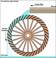
Backshot wheel
.svg.png)
A backshot wheel (also called pitchback) is a variety of overshot wheel where the water is introduced just behind the summit of the wheel. It combines the advantages from breastshot and overshot systems, since the full amount of the potential energy released by the falling water is harnessed as the water descends the back of the wheel (as in overshot wheel) while it also gains power from the water's current past the bottom of the wheel (as in breastshot wheel).
A backshot wheel continues to function until the water in the wheel pit rises well above the height of the axle, when any other overshot wheel will be stopped or even destroyed. This makes the technique particularly suitable for streams that experience extreme seasonal variations in flow, and reduces the need for complex sluice and tail race configurations.
The direction of rotation of a backshot wheel is the same as that of a breastshot wheel at the same location so it can easily replace one, without causing the directional gearing in the mill to be changed. This would increase the power available while only requiring a change to be made to the water level in the top pond, which in some cases is economically viable.
Suspension wheels and rim-gears

Two early improvements were suspension wheels and rim gearing. Suspension wheels are constructed in the same manner as a bicycle wheel, the rim being supported under tension from the hub- this led to larger lighter wheels than the former design where the heavy spokes were under compression. Rim-gearing entailed adding a notched wheel to the rim or shroud of the wheel. A stub gear engaged the rim-gear and took the power into the mill using an independent line shaft. This removed the rotative stress from the axle which could thus be lighter, and also allowed more flexibility in the location of the power train. The shaft rotation was geared up from that of the wheel which led to less power loss. An example of this design pioneered by Thomas Hewes and refined by William Fairburn can be seen at the 1849 restored wheel at the Portland Basin Canal Warehouse.[53]
Efficiency
Overshot (and particularly backshot) wheels are the most efficient type; a backshot steel wheel can be more efficient (about 60%) than all but the most advanced and well-constructed turbines. In some situations an overshot wheel is preferable to a turbine.[54]
The development of the hydraulic turbine wheels with their improved efficiency (>67%) opened up an alternative path for the installation of water wheels in existing mills, or redevelopment of abandoned mills.
Power calculations
In an undershot wheel or a run of the river wheel the power is dependant to the kinetic energy of the river. Approximate power can be calculated.
- Power in Watts= 100 × A × V3 ×C
- A = Area of paddles in the water (square meters)
- V = Velocity of the stream in meters per second
- C = Efficiency Constant (assume 1 for a water to wire efficiency of 20%)
- Rotational speed of the wheel = 9 × V /D rpm
- D = diameter in meters[55]
For a breast shot or over shot wheel both potential energy and kinetic energy must be considered. This takes the form of the weight of water in the buckets and the vertical distance travelled. A rule of thumb formula is
- Power in Watts = 4 × Q × H × C
- Q = Weight of water (volume per sec x capacity of the buckets)
- V = Velocity of the stream in meters per second
- H = Head, or height difference of water between the lip of the flume (head race) and the tailrace
- C = Efficiency Constant
The optimal rotational speed of a breast shot or overshot wheel is approximately:
- Rotational speed of the wheel= 21/ √D
- D = diameter of the wheel in metres[55]
Hydraulic wheel
A recent development of the breastshot wheel is a hydraulic wheel which effectively incorporates automatic regulation systems. The Aqualienne is one example. It generates between 37 kW and 200 kW of electricity from a 20m³ waterflow with a head of 1 to 3.5m.[56] It is designed to produce electricity at the sites of former watermills.
Hydraulic wheel part reaction turbine
A parallel development is the hydraulic wheel/part reaction turbine that also incorporates a weir into the centre of the wheel but uses blades angled to the water flow. The WICON-Stem Pressure Machine (SPM) exploits this flow.[57] Estimated efficiency 67%.
The University of Southampton School of Civil Engineering and the Environment in the UK has investigated both types of Hydraulic wheel machines and has estimated their hydraulic efficiency and suggested improvements, i.e. The Rotary Hydraulic Pressure Machine. (Estimated maximum efficiency 85%).[58]
These type of water wheels have high efficiency at part loads / variable flows and can operate at very low heads, < 1 metre. Combined with direct drive Axial Flux Permanent Magnet Alternators and power electronics they offer a viable alternative for low head hydroelectric power generation.
Water-lifting


In water-raising devices rotary motion is typically more efficient than machines based on oscillating motion.[59]
The compartmented water wheel comes in two basic forms, the wheel with compartmented body (Latin tympanum) and the wheel with compartmented rim or a rim with separate, attached containers.[59] The wheels could be either turned by the flow of water, men treading on its outside or by animals by means of a sakia gear.[60] While the tympanum had a large discharge capacity, it could lift the water only to less than the height of its own radius and required a large torque for rotating.[60] These constructional deficiencies were overcome by the wheel with a compartmented rim which was a less heavy design with a higher lift.[61]
- Ptolemaic Egypt
The earliest literary reference to a water-driven, compartmented wheel appears in the technical treatise Pneumatica (chap. 61) of the Greek engineer Philo of Byzantium (ca. 280–220 BC).[62] In his Parasceuastica (91.43−44), Philo advises the use of such wheels for submerging siege mines as a defensive measure against enemy sapping.[63] Compartmented wheels appear to have been the means of choice for draining dry docks in Alexandria under the reign of Ptolemy IV (221−205 BC).[63] Several Greek papyri of the 3rd to 2nd century BC mention the use of these wheels, but don't give further details.[63] The non-existence of the device in the Ancient Near East before Alexander's conquest can be deduced from its pronounced absence from the otherwise rich oriental iconography on irrigation practices.[64][65][66][67] Unlike other water-lifting devices and pumps of the period though, the invention of the compartmented wheel cannot be traced to any particular Hellenistic engineer and may have been made in the late 4th century BC in a rural context away from the metropolis of Alexandria.[68]
The earliest depiction of a compartmented wheel is from a tomb painting in Ptolemaic Egypt which dates to the 2nd century BC. It shows a pair of yoked oxen driving the wheel via a sakia gear, which is here for the first time attested, too.[69] The Greek sakia gear system is already shown fully developed to the point that "modern Egyptian devices are virtually identical".[69] It is assumed that the scientists of the Museum of Alexandria, at the time the most active Greek research center, may have been involved in its invention.[70] An episode from the Alexandrian War in 48 BC tells of how Caesar's enemies employed geared water wheels to pour sea water from elevated places on the position of the trapped Romans.[71]
Around 300 AD, the noria was finally introduced when the wooden compartments were replaced with inexpensive ceramic pots that were tied to the outside of an open-framed wheel.[68]
See also
- Hydroelectricity
- Turgo Wheel
- Water Turbine
- Pelton Wheel
- Permanent Magnet Alternator
- Micro Hydro Generator
- Renewable Energy
- Watermill
- Watermills in the United Kingdom
- Claverton Pumping Station – canal water pumping station
- Derby Industrial Museum – former silk mill
- Laxey Wheel – pumping water from a mine
- Snaefell Wheel – pumping water from a mine
- Water wheel (heraldry)
- For devices to lift water for irrigation
- Devices to lift water for land drainage
References
Notes
- ↑ Dictionary definition of "tailrace"
- ↑ Musson; Robinson (1969). Science and Technology in the Industrial Revolution. University of Toronto Press. p. 69.
- 1 2 Thomson, Ross (2009). Structures of Change in the Mechanical Age: Technological Invention in the United States 1790-1865. Baltimore, MD: The Johns Hopkins University Press. p. 34. ISBN 978-0-8018-9141-0.
- 1 2 Oleson 1984, pp. 325ff.; Oleson 2000, pp. 217–302; Donners, Waelkens & Deckers 2002, pp. 10−15; Wikander 2000, pp. 371−400
- ↑ Wikander 2000, pp. 395; Oleson 2000, p. 229
It is no surprise that all the water-lifting devices that depend on subdivided wheels or cylinders originate in the sophisticated, scientifically advanced Hellenistic period, ...
- ↑ Örjan Wikander (2008). "Chapter 6: Sources of Energy and Exploitation of Power". In John Peter Oleson. The Oxford Handbook of Engineering and Technology in the Classical World. Oxford University Press. pp. 141–2. ISBN 0-19-518731-8.
- ↑ Adriana de Miranda (2007). Water architecture in the lands of Syria: the water-wheels. L'Erma di Bretschneider. pp. 38–9. ISBN 88-8265-433-8.
- ↑ Wikander 2000, pp. 396f.; Donners, Waelkens & Deckers 2002, p. 11; Wilson 2002, pp. 7f.
- ↑ Wikander 1985, p. 160; Wikander 2000, p. 396
- ↑ Oleson 2000, pp. 234, 269
- ↑ Oleson 2000, pp. 269−271
- ↑ Wikander 2000, pp. 373f.; Donners, Waelkens & Deckers 2002, p. 12
- ↑ Wikander 2000, p. 375; Donners, Waelkens & Deckers 2002, p. 13
- ↑ Donners, Waelkens & Deckers 2002, p. 11; Oleson 2000, p. 236
- ↑ Wikander 2000, p. 375
- ↑ Donners, Waelkens & Deckers 2002, pp. 12f.
- ↑ Greene 2000, p. 39
- ↑ Wilson 1995, pp. 507f.; Wikander 2000, p. 377; Donners, Waelkens & Deckers 2002, p. 13
- ↑ De Rebus Bellicis (anon.), chapter XVII, text edited by Robert Ireland, in: BAR International Series 63, part 2, p. 34
- ↑ Wikander 2000, pp. 372f.; Wilson 2002, p. 3
- ↑ Murphy 2005
- 1 2 Wikander 1985, pp. 155–157
- ↑ Glick, p. 178
- 1 2 3 Robert, Friedel, A Culture of Improvement. MIT Press. Cambridge, Massachusetts. London, England. (2007). pp. 31-2b.
- 1 2 Robert, A. Howard, Primer on Water Wheels, Vol 15, No. 3 (1983) pp26-33. Published by: Association for Preservation Technology International. p26.
- ↑ Terry S, Reynolds, Stronger than a Hundred Men; A History of the Vertical Water Wheel. Baltimore; Johns Hopkins University Press, 1983. Robert, Friedel, A Culture of Improvement. MIT Press. Cambridge, Massachusetts. London, England. (2007). p. 33.
- ↑ Robert, Friedel, A Culture of Improvement. MIT Press. Cambridge, Massachusetts. London, England. (2007). p. 34
- ↑ Robert, Friedel, A Culture of Improvement. MIT Press. Cambridge, Massachusetts. London, England. (2007)
- ↑ Anthony Fitzherbert, Surveying (London, 1539, reprinted in [Robert Vansitarrt, ed] Certain Ancient Tracts Concerning the Management of Landed Property Reprinted [London, 1767.] pg. 92.
- ↑ Leonardo da Vinci, MS F, 44r, in Les manuscrits de Leonardo da Vinci, ed Charles Ravaisson-Moilien (Paris, 1889), vol.4; cf, Codex Madrid, vol. 1, 69r [The Madrid Codices], trans. And transcribed by Ladislao Reti (New York, 1974), vol. 4.
- ↑ Smeaton, "An Experiemental Inquiry Concerning the Natural Powers of Water and Wind to Turn Mills, and Other Machines, depending on Circular Motion," Royal Society, Philosophical Transactions of the Royal Society of London 51 (1759); 124-125
- ↑ Torricelli, Evangelista, Opere, ed. Gino Loria and Giuseppe Vassura (Rome, 1919.)
- ↑ Torricella, Evangelica, Opere, ed. Gino Loria and Giuseppe Vassura (Rome, 1919.)
- ↑ Needham, p. 392
- ↑ Needham, p. 370
- ↑ Morton, p. 70
- ↑ Needham, p. 158
- ↑ Reynolds, p. 14
- ↑ Wikander 2000, p. 400:
This is also the period when water-mills started to spread outside the former Empire. According to Cedrenus (Historiarum compendium), a certain Metrodoros who went to India in c. A.D. 325 "constructed water-mills and baths, unknown among them [the Brahmans] till then".
- ↑ Pacey, p. 10
- ↑ Pacey, p. 36
- ↑ Siddiqui
- ↑ al-Hassani et al., p.115
- ↑ Lucas, Adam (2006), Wind, Water, Work: Ancient and Medieval Milling Technology, Brill Publishers, p. 26, ISBN 90-04-14649-0
- ↑ Donald Routledge Hill (1996), A history of engineering in classical and medieval times, Routledge, pp. 145–6, ISBN 0-415-15291-7
- ↑ Lucas, p. 10
- ↑ Ahmad Y Hassan, Transfer Of Islamic Technology To The West, Part II: Transmission Of Islamic Engineering
- ↑ Lucas, p.11
- ↑ Hill; see also Mechanical Engineering)
- ↑ Ahmad Y Hassan, Flywheel Effect for a Saqiya.
- ↑ Stream wheel term and specifics
- ↑ The History of Science and Technology by Bryan Bunch with Alexander Hellmans pp.114
- ↑
- Nevell, Mike; Walker (2001). Portland Basin and the archaeology of the Canal Warehouse. Tameside Metropolitan Borough with University of Manchester Archaeological Unit. ISBN 1-871324-25-4.
- ↑ For a discussion of the different types of water wheels, see Syson, p. 76-91
- 1 2 British Hydro Water wheel information.
- ↑ http://www.h3eindustries.com/How-does-an-Aqualienne%C2%AE-work? Aqualienne breastshot wheel
- ↑ Oewatec
- ↑ Low Head Hydro
- 1 2 Oleson 2000, p. 229
- 1 2 Oleson 2000, p. 230
- ↑ Oleson 2000, pp. 231f.
- ↑ Oleson 2000, p. 233
- 1 2 3 Oleson 2000, pp. 234
- ↑ Oleson 2000, pp. 235:
The sudden appearance of literary and archaeological evidence for the compartmented wheel in the third century B.C. stand in marked contrast to the complete absence of earlier testimony, suggesting that the device was invented not long before.
- ↑ An isolated passage in the Hebrew Deuteronomy (11.10−11) about Egypt as a country where you sowed your seed and watered it with your feet is interpreted as a metaphor referring to the digging of irrigation channels rather than treading a water wheel (Oleson 2000, pp. 234).
- ↑ As for a Mesopotamian connection: Schioler 1973, p. 165−167:
References to water-wheels in ancient Mesopotamia, found in handbooks and popular accounts, are for the most part based on the false assumption that the Akkadian equivalent of the logogram GIS.APIN was nartabu and denotes an instrument for watering ("instrument for making moist").
As a result of his investigations, Laessoe writes as follows on the question of the saqiya: "I consider it unlikely that any reference to the saqiya will appear in ancient Mesopotamian sources." In his opinion, we should turn our attention to Alexandria, "where it seems plausible to assume that the saqiya was invented."
- ↑ Adriana de Miranda (2007), Water architecture in the lands of Syria: the water-wheels, L'Erma di Bretschneider, pp. 48f., ISBN 88-8265-433-8 concludes that the Akkadian passages "are couched in terms too general too allow any conclusion as to the exact structure" of the irrigation apparatus, and states that "the latest official Chicago Assyrian Dictionary reports meanings not related to types of irrigation system".
- 1 2 Oleson 2000, pp. 235
- 1 2 Oleson 2000, pp. 234, 270
- ↑ Oleson 2000, pp. 271f.
- ↑ Oleson 2000, p. 271
Bibliography
- Soto Gary, Water Wheel. vol. 163. No. 4. (Jan., 1994), p. 197
- al-Hassani, S.T.S., Woodcock, E. and Saoud, R. (2006) 1001 inventions : Muslim heritage in our world, Manchester : Foundation for Science Technology and Civilisation, ISBN 0-9552426-0-6
- Allan. April 18, 2008. Undershot Water Wheel. Retrieved from http://www.builditsolar.com/Projects/Hydro/UnderShot/WaterWheel.htm
- Donners, K.; Waelkens, M.; Deckers, J. (2002), "Water Mills in the Area of Sagalassos: A Disappearing Ancient Technology", Anatolian Studies, Anatolian Studies, Vol. 52, 52, pp. 1–17, doi:10.2307/3643076, JSTOR 3643076
- Glick, T.F. (1970) Irrigation and society in medieval Valencia, Cambridge, MA: Belknap Press of Harvard University Press, ISBN 0-674-46675-6
- Greene, Kevin (2000), "Technological Innovation and Economic Progress in the Ancient World: M.I. Finley Re-Considered", The Economic History Review, 53 (1), pp. 29–59, doi:10.1111/1468-0289.00151
- Hill, D.R. (1991) "Mechanical Engineering in the Medieval Near East", Scientific American, 264 (5:May), p. 100-105
- Lucas, A.R. (2005). "Industrial Milling in the Ancient and Medieval Worlds: A Survey of the Evidence for an Industrial Revolution in Medieval Europe". Technology and Culture. 46 (1): 1–30. doi:10.1353/tech.2005.0026.
- Lewis, M.J.T. (1997) Millstone and Hammer: the origins of water power, University of Hull Press, ISBN 0-85958-657-X
- Morton, W.S. and Lewis, C.M. (2005) China: Its History and Culture, 4th Ed., New York : McGraw-Hill, ISBN 0-07-141279-4
- Murphy, Donald (2005), Excavations of a Mill at Killoteran, Co. Waterford as Part of the N-25 Waterford By-Pass Project (PDF), Estuarine/ Alluvial Archaeology in Ireland. Towards Best Practice, University College Dublin and National Roads Authority
- Needham, J. (1965) Science and Civilization in China - Vol. 4: Physics and physical technology - Part 2: Mechanical engineering, Cambridge University Press, ISBN 0-521-05803-1
- Nuernbergk, D.M. (2005) Wasserräder mit Kropfgerinne: Berechnungsgrundlagen und neue Erkenntnisse, Detmold : Schäfer, ISBN 3-87696-121-1
- Nuernbergk, D.M. (2007) Wasserräder mit Freihang: Entwurfs- und Berechnungsgrundlagen, Detmold : Schäfer, ISBN 3-87696-122-X
- Pacey, A. (1991) Technology in World Civilization: A Thousand-year History, 1st MIT Press ed., Cambridge, Massachusetts : MIT, ISBN 0-262-66072-5
- Oleson, John Peter (1984), Greek and Roman Mechanical Water-Lifting Devices: The History of a Technology, University of Toronto Press, ISBN 90-277-1693-5
- Oleson, John Peter (2000), "Water-Lifting", in Wikander, Örjan, Handbook of Ancient Water Technology, Technology and Change in History, 2, Leiden: Brill, pp. 217–302, ISBN 90-04-11123-9
- Reynolds, T.S. (1983) Stronger Than a Hundred Men: A History of the Vertical Water Wheel, Johns Hopkins studies in the history of technology: New Series 7, Baltimore: Johns Hopkins University Press, ISBN 0-8018-2554-7
- Schioler, Thorkild (1973), Roman and Islamic Water-Lifting Wheels, Odense University Press, ISBN 87-7492-090-1
- Shannon, R. 1997. Water Wheel Engineering. Retrieved from http://permaculturewest.org.au/ipc6/ch08/shannon/index.html.
- Siddiqui, Iqtidar Husain (1986). "Water Works and Irrigation System in India during Pre-Mughal Times". Journal of the Economic and Social History of the Orient. 29 (1): 52–77. doi:10.1163/156852086X00036.
- Syson, l. (1965) British Water-mills, London : Batsford, 176 p.
- Wikander, Örjan (1985), "Archaeological Evidence for Early Water-Mills. An Interim Report", History of Technology, 10, pp. 151–179
- Wikander, Örjan (2000), "The Water-Mill", in Wikander, Örjan, Handbook of Ancient Water Technology, Technology and Change in History, 2, Leiden: Brill, pp. 371–400, ISBN 90-04-11123-9
- Wilson, Andrew (1995), "Water-Power in North Africa and the Development of the Horizontal Water-Wheel", Journal of Roman Archaeology, 8, pp. 499–510
- Wilson, Andrew (2002), "Machines, Power and the Ancient Economy", The Journal of Roman Studies, 92, pp. 1–32, doi:10.2307/3184857, JSTOR 3184857
External links
| Look up water wheel in Wiktionary, the free dictionary. |
| Wikimedia Commons has media related to Water wheels. |
- Glossary of water wheel terms
- Essay/audio clip
- WaterHistory.org - Several articles concerning water wheels
- Computer simulation of an undershot water wheel
- Persian Wheel in India, 1814-1815 painting with explanatory text, at British Library website.
- Computer simulation of an overshot water wheel
| Hydroelectricity generation | 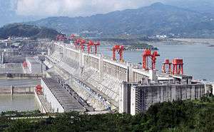 | |
|---|---|---|
| Hydroelectricity equipment | ||