Unitary Plan Wind Tunnel (Mountain View, California)
Another Unitary Plan Wind Tunnel existed at the NASA Langley Research Center
|
Unitary Plan Wind Tunnel | |
|
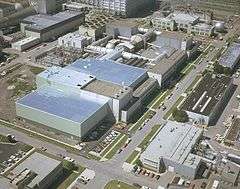
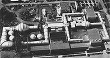
Aerial view of the Unitary Plan Wind Tunnel complex, 1974 | |
   | |
| Location | Mountain View, California |
|---|---|
| Coordinates | 37°25′0.9″N 122°3′37.71″W / 37.416917°N 122.0604750°WCoordinates: 37°25′0.9″N 122°3′37.71″W / 37.416917°N 122.0604750°W |
| Built | 1955 |
| NRHP Reference # | 85002799 |
| Significant dates | |
| Added to NRHP | October 3, 1985[1] |
| Designated NHL | October 3, 1985[2] |
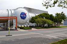
The Unitary Plan Wind Tunnel, located at the NASA Ames Research Center in Moffett Federal Airfield, Mountain View, California, United States, is a research facility used extensively to design and test new generations of aircraft, both commercial and military, as well as NASA space vehicles, including the Space Shuttle. The facility was completed in 1955 and is one of five facilities created after the 1949 Unitary Wind Tunnel Plan Act supporting aeronautics research.
Background
After the construction of the Variable Density Tunnel at Langley in 1921,[3] the National Advisory Committee for Aeronautics built a variety of technical research facilities upon which the American aircraft industry was based. These facilities enabled the American aircraft industry to dominate the skies in both commercial and military aviation. By 1945, America's lead in the field of aviation seemed to be evaporating. The technological achievements of the German missiles and jet aircraft indicated a lag in American aeronautical research.
In 1949, Congress passed the Unitary Wind Tunnel Plan Act, under which the Federal government coordinated a national plan of facility construction encompassing NACA, as well as the Air Force, private industry, and universities. The Unitary Plan resulted in the construction of a new series of wind tunnel complexes to support the American aircraft industry, including the Ames Unitary Plan Wind Tunnel Complex.
Construction
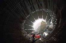
Construction of this facility began in 1950-1951 and continued until 1955. Because no one wind tunnel could meet all the demands for additional research facilities simulating the entire range of aircraft and missile flight, NACA chose to build the Ames tunnel with three separate test sections drawing power from a common centralized power plant. The transonic test section spanned 11 by 11 feet (3.3 x 3.3 m), while the two supersonic sections were smaller: nine by seven feet (2.7 x 2.1 m) and eight by seven feet (2.4 x 2.1 m). Giant valves 20 feet (6 m) in diameter supplied air from one supersonic leg to another.
The American West Coast aircraft industry quickly capitalized on the Ames Unitary Plan Wind Tunnel Complex. The famed Boeing fleet of commercial transports and the Douglas DC-8, DC-9, and DC-10 were all tested here; as well as military aircraft such as the F-111 fighter, the C-5A Galaxy transport and the B-1 Lancer bomber. In addition to aircraft, in the 1960s and 1970s almost all NASA manned space vehicles including the Space Shuttle were tested in the Ames Unitary Plan Wind tunnel complex.
The Unitary Plan Wind Tunnel has three closed-loop wind tunnels, each with its own model test section, but all sharing the same powerful electric motors (100,000 horsepower, 75,000 kilowatts) driving their compressors to propel the air within them. Because of this shared layout, only one UPWT test section can be used at a time. The three wind tunnels that are part of this system are:
- 11-by 11-foot Transonic Test Section. A closed-return, variable-density tunnel with a fixed-geometry, ventilated test section with a flexible wall nozzle with a Mach range of 0.20 to 1.45.[4]
- 9-by 7-foot Supersonic Test Section. A closed circuit, single return, variable density, continuous flow wind tunnel with a Mach range of 1.55 to 2.55.
- 8-by 7-foot Supersonic Test Section. A closed circuit, single return, variable density, continuous flow wind tunnel
The Unitary Plan Wind Tunnel was declared a National Historic Landmark in 1985.[2][5]
Engineering
The major element of the tunnel complex is its drive system, consisting of four intercoupled electric motors. The transonic wind tunnel is a closed-return, variable density tunnel with a fixed geometry, ventilated throat, and a single-jack flexible nozzle. Airflow is produced by a three-stage, axial-flow compressor powered by four-wound-rotor, variable-speed induction motors. For conventional steady-state tests, models are generally supported on a string. A Schlieren system, one that allows regions of varying refraction in a transparent medium caused by pressure or temperature differences and detectable by photographing the passage of a beam of light, is available for studying flow patterns, either by direct viewing or by photographs.
The details of the larger supersonic tunnel are much the same, except that it is equipped with an asymmetric, sliding-block nozzle and the airflow is produced by an 11-stage, axial-flow compressor powered by four variable-speed, wound-rotor, induction motors. The smaller supersonic tunnel is a closed-return, variable-density tunnel equipped with a symmetrical, flexible-wall throat and the sidewalls are positioned by a series of jacks operated by hydraulic motors.
See also
References
- ↑ National Park Service (2006-03-15). "National Register Information System". National Register of Historic Places. National Park Service.
- 1 2 "Unitary Plan Wind Tunnel". National Historic Landmark summary listing. National Park Service. Retrieved 2008-04-12.
- ↑ "Unitary Plan Wind Tunnel". California's Historic Silicon Valley. National Park Service. Retrieved 2007-03-12.
- ↑ http://www.loc.gov/rr/frd/pdf-files/Western_Hemisphere_Wind_Tunnels.pdf
- ↑ Harry A. Butowsky (May 15, 1984). "National Register of Historic Places Inventory-Nomination: Unitary Plan Wind Tunnel / Unitary Plan Facility" (pdf). National Park Service. and Accompanying photo, aerial, from 1984 (32 KB)
External links
- NASA Ames Research Center Wind Tunnels web site
- Aviation: From Sand Dunes to Sonic Booms, a National Park Service Discover Our Shared Heritage Travel Itinerary
Spaceflight National Historic Landmarks | ||
|---|---|---|
| Alabama |  | |
| Florida | ||
| Arizona | ||
| California | ||
| Mississippi | ||
| New Mexico | ||
| Ohio | ||
| Texas | ||
| Maryland | ||
| Virginia | ||