Sagnac effect

The Sagnac effect (also called Sagnac interference), named after French physicist Georges Sagnac, is a phenomenon encountered in interferometry that is elicited by rotation. The Sagnac effect manifests itself in a setup called a ring interferometer. A beam of light is split and the two beams are made to follow the same path but in opposite directions. To act as a ring the trajectory must enclose an area. On return to the point of entry the two light beams are allowed to exit the ring and undergo interference. The relative phases of the two exiting beams, and thus the position of the interference fringes, are shifted according to the angular velocity of the apparatus. This arrangement is also called a Sagnac interferometer.
A gimbal mounted mechanical gyroscope remains pointing in the same direction after spinning up, and thus can be used as a rotational reference for an inertial navigation system. With the development of so-called laser gyroscopes and fiber optic gyroscopes based on the Sagnac effect, the bulky mechanical gyroscope is replaced by one having no moving parts in many modern inertial navigation systems. The principles behind the two devices are different, however. A conventional gyroscope relies on the principle of conservation of angular momentum whereas the sensitivity of the ring interferometer to rotation arises from the invariance of the speed of light for all inertial frames of reference.
Description and operation

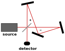
Typically 3 or more mirrors are used, so that counter-propagating light beams follow a closed path such as a triangle or square.(Fig. 1) Alternatively fiber optics can be employed to guide the light through a closed path.(Fig. 2) If the platform on which the ring interferometer is mounted is rotating, the interference fringes are displaced compared to their position when the platform is not rotating. The amount of displacement is proportional to the angular velocity of the rotating platform. The axis of rotation does not have to be inside the enclosed area.
The Sagnac effect in a circular loop can be understood on an intuitive level as follows. When the loop is rotating, the point of entry/exit moves during the transit time of the light. The backwards-propagating beam covers less distance than the forwards-propagating beam and arrives earlier.(Fig. 3) This creates a shift in the interference pattern. The shift of the interference fringes is thereby proportional to the platform's angular velocity.
This simplistic explanation, however, breaks down in cases where the light is propagating through a medium which has a refractive index that is not one. In that case, relativistic addition of velocities can be used to calculate the lab frame phase velocity of the light moving in the same direction as the rotation as well as for the light moving in the opposite direction from the rotation. The difference in lab frame phase velocities determines the difference in travel times, and this difference in travel times can be multiplied by the optical frequency to determine a phase difference.
The rotation thus measured is an absolute rotation, that is, the platform's rotation with respect to an inertial reference frame.
History
Early suggestions to build a giant ring interferometer to measure the rotation of the Earth were made by Oliver Lodge in 1897, and then by Albert Abraham Michelson in 1904. They hoped that with such an interferometer, it would be possible to decide between the idea of a stationary aether, and an aether which is completely dragged by the Earth. That is, if the hypothetical aether were carried along by the Earth (or by the interferometer) the result would be negative, while a stationary aether would give a positive result.[1][2][3] Max von Laue in 1911 continued the theoretical work of Michelson, and also incorporated special relativity in his calculations. He predicted a positive result (to first order in v/c) for both special relativity and for the stationary aether, because in those theories the speed of light is independent of the velocity of the source, and thus the propagation time for the counter-propagating rays is not the same when viewed from inertial frames of reference; only complete-aether-drag models would give a negative result.[4][5] While Laue confined his investigations on inertial frames, Paul Langevin (1921/35) and others described the effect when viewed from rotating reference frames (in both special and general relativity, see Born coordinates).[6][7]
In practice, the first interferometry experiment aimed at observing the correlation of angular velocity and phase-shift was performed by the French scientist Georges Sagnac in 1913. Its purpose was to detect "the effect of the relative motion of the ether".[8][9] Sagnac believed that his results constituted proof of the existence of a stationary aether. However, as explained above, two years earlier, Max von Laue had already shown that this effect is consistent with special relativity.[4] An experiment conducted in 1911 by Franz Harress, aimed at making measurements of the Fresnel drag of light propagating through moving glass, was in 1920 recognized by Laue as actually constituting a Sagnac experiment. Not aware of the Sagnac effect, Harress had realized the presence of an "unexpected bias" in his measurements, but was unable to explain its cause.[10]
In 1926, an ambitious ring interferometry experiment was set up by Albert Michelson and Henry Gale. The aim was to find out whether the rotation of the Earth has an effect on the propagation of light in the vicinity of the Earth. The Michelson–Gale–Pearson experiment was a very large ring interferometer, (a perimeter of 1.9 kilometer), large enough to detect the angular velocity of the Earth. The outcome of the experiment was that the angular velocity of the Earth as measured by astronomy was confirmed to within measuring accuracy. The ring interferometer of the Michelson-Gale experiment was not calibrated by comparison with an outside reference (which was not possible, because the setup was fixed to the Earth). From its design it could be deduced where the central interference fringe ought to be if there would be zero shift. The measured shift was 230 parts in 1000, with an accuracy of 5 parts in 1000. The predicted shift was 237 parts in 1000.[11]
Theory

The shift in interference fringes in a ring interferometer can be viewed intuitively as a consequence of the different distances that light travels due to the rotation of the ring.(Fig. 3)[12] The simplest derivation is for a circular ring of radius R, with a refractive index of one, rotating at an angular velocity of , but the result is general for loop geometries with other shapes. If a light source emits in both directions from one point on the rotating ring, light traveling in the same direction as the rotation direction needs to travel more than one circumference around the ring before it catches up with the light source from behind. The time that it takes to catch up with the light source is given by:


is the distance (black bold arrow in Fig. 3) that the mirror has moved in that same time:


Eliminating from the two equations above we get:

Likewise, the light traveling in the opposite direction of the rotation will travel less than one circumference before hitting the light source on the front side. So the time for this direction of light to reach the moving source again is:

The time difference is

For , this reduces to


where A is the area of the ring.

Although this simple derivation is for a circular ring with an index of refraction of one, the result holds true for any shape of rotating loop with area A.(Fig. 4)
For more complicated shapes, or other refractive index values, the same result can be derived by calculating the optical phase shift in each direction using Fermat's principle and taking into account the different phase velocities for the different propagation directions in an inertial laboratory frame, which can be calculated using relativistic addition of velocities.[13]
We imagine a screen for viewing fringes placed at the light source (or we use a beamsplitter to send light from the source point to the screen). Given a steady light source, interference fringes will form on the screen with a fringe displacement proportional to the time differences required for the two counter-rotating beams to traverse the circuit. The phase shift is , which causes fringes to shift in proportion to and .


At non-relativistic speeds, the Sagnac effect is a simple consequence of the source independence of the speed of light. In other words, the Sagnac experiment does not distinguish between pre-relativistic physics and relativistic physics.[12]
When light propagates in fibre optic cable, the setup is effectively a combination of a Sagnac experiment and the Fizeau experiment. In glass the speed of light is slower than in vacuum, and the optical cable is the moving medium. In that case the relativistic velocity addition rule applies. Pre-relativistic theories of light propagation cannot account for the Fizeau effect. (By 1900 Lorentz could account for the Fizeau effect, but by that time his theory had evolved to a form where in effect it was mathematically equivalent to special relativity.)
Since emitter and detector are traveling at the same speeds, Doppler effects cancel out, so the Sagnac effect does not involve the Doppler effect. In the case of ring laser interferometry, it is important to be aware of this. When the ring laser setup is rotating, the counterpropagating beams undergo frequency shifts in opposite directions. This frequency shift is not a Doppler shift, but is rather an optical cavity resonance effect, as explained below in Ring lasers.

The Sagnac effect has stimulated a century long debate on its meaning and interpretation,[14][15][16] much of this debate being surprising since the effect is perfectly well understood in the context of special relativity where from the rotating light source's point of view the phase difference is due to the line of simultaneity along the light path not forming a closed loop in spacetime.[17]
Modified versions of the experiment have been proposed[18] with the light source allowed to move along a (not necessarily circular) light path. This configuration introduces another reason for the phase difference: according to the light source the two signals now follow different paths in space. Some authors refer to this effect as Sagnac effect[16][19] although in this case the discrepancy need not be due to the lines of simultaneity not forming closed loops.
An example of the modified configuration is shown in Fig. 5, the measured phase difference in both a standard fibre optic gyroscope, shown on the left, and a modified fibre optic conveyor, shown on the right, conform to the equation Δt = 2vL/c2, whose derivation is based on the constant speed of light. It is evident from this formula that the total time delay is equal to the cumulative time delays along the entire length of fibre, regardless whether the fibre is in a rotating section of the conveyor, or a straight section.
This equation is invalid, however, if the light source's path in space does not follow that of the light signals, for example in the standard rotating platform case (FOG) but with a non-circular light path. In this case the phase difference formula necessarily involves the area enclosed by the light path due to Stokes' theorem.[17]
Other generalizations
A relay of pulses that circumnavigates the Earth, verifying precise synchronization, is also recognized as a case requiring correction for the Sagnac effect. In 1984 a verification was set up that involved three ground stations and several GPS satellites, with relays of signals both going eastward and westward around the world.[20] In the case of a Sagnac interferometer a measure of difference in arrival time is obtained by producing interference fringes, and observing the fringe shift. In the case of a relay of pulses around the world the difference in arrival time is obtained directly from the actual arrival time of the pulses. In both cases the mechanism of the difference in arrival time is the same: the Sagnac effect.
The Hafele–Keating experiment is also recognized as a counterpart to Sagnac effect physics. In the actual Hafele–Keating experiment the mode of transport (long-distance flights) gave rise to time dilation effects of its own, and calculations were needed to separate the various contributions. For the (theoretical) case of clocks that are transported so slowly that time dilation effects arising from the transport are negligible the amount of time difference between the clocks when they arrive back at the starting point will be equal to the time difference that is found for a relay of pulses that travels around the world: 207 nanoseconds.[21]
Reference frames
The Sagnac effect is not an artifact of the choice of reference frame. It is independent of the choice of reference frame, as is shown by a calculation that invokes the metric tensor for an observer at the axis of rotation of the ring interferometer and rotating with it yielding the same outcome. If one starts with the Minkowski metric and does the coordinate conversions and (see Born coordinates), the line element of the resultant metric is


where
- is proper time for the central observer,
- is distance from the center,
- is the angular distance along the ring from the direction the central observer is facing,
- is the direction perpendicular to the plane of the ring, and
- is the rate of rotation of the ring and the observer.


Under this metric, the speed of light tangent to the ring is depending on whether the light is moving against or with the rotation of the ring. Note that only the case of is inertial. For this frame of reference is non-inertial, which is why the speed of light at positions distant from the observer (at ) can vary from .


Practical uses
The Sagnac effect is employed in current technology. One use is in inertial guidance systems. Ring laser gyroscopes are extremely sensitive to rotations, which need to be accounted for if an inertial guidance system is to return accurate results. The ring laser also can detect the sidereal day, which can also be termed "mode 1". Global navigation systems, such as GPS, GLONASS, COMPASS or Galileo, need to take the rotation of the Earth into account in the procedures of using radio signals to synchronize clocks.
Ring lasers

Fibre optic gyroscopes are sometimes referred to as 'passive ring interferometers'. A passive ring interferometer uses light entering the setup from outside. The interference pattern that is obtained is a fringe pattern, and what is measured is a phase shift.
It is also possible to construct a ring interferometer that is self-contained, based on a completely different arrangement. This is called a ring laser or ring laser gyroscope. The light is generated and sustained by incorporating laser excitation in the path of the light.
To understand what happens in a ring laser cavity, it is helpful to discuss the physics of the laser process in a laser setup with continuous generation of light. As the laser excitation is started, the molecules inside the cavity emit photons, but since the molecules have a thermal velocity, the light inside the laser cavity is at first a range of frequencies, corresponding to the statistical distribution of velocities. The process of stimulated emission makes one frequency quickly outcompete other frequencies, and after that the light is very close to monochromatic.

For the sake of simplicity, assume that all emitted photons are emitted in a direction parallel to the ring. Fig. 7 illustrates the effect of the ring laser's rotation. In a linear laser, an integer multiple of the wavelength fits the length of the laser cavity. This means that in traveling back and forth the laser light goes through an integer number of cycles of its frequency. In the case of a ring laser the same applies: the number of cycles of the laser light's frequency is the same in both directions. This quality of the same number of cycles in both directions is preserved when the ring laser setup is rotating. The image illustrates that there is wavelength shift (hence a frequency shift) in such a way that the number of cycles is the same in both directions of propagation.
By bringing the two frequencies of laser light to interference a beat frequency can be obtained; the beat frequency is the difference between the two frequencies. This beat frequency can be thought of as an interference pattern in time. (The more familiar interference fringes of interferometry are a spatial pattern). The period of this beat frequency is linearly proportional to the angular velocity of the ring laser with respect to inertial space. This is the principle of the ring laser gyroscope, widely used in modern inertial navigation systems.
Zero point calibration
In passive ring interferometers, the fringe displacement is proportional to the first derivative of angular position; careful calibration is required to determine the fringe displacement that corresponds to zero angular velocity of the ring interferometer setup. On the other hand, ring laser interferometers do not require calibration to determine the output that corresponds to zero angular velocity. Ring laser interferometers are self-calibrating. The beat frequency will be zero if and only if the ring laser setup is non-rotating with respect to inertial space.
Fig. 8 illustrates the physical property that makes the ring laser interferometer self-calibrating. The grey dots represent molecules in the laser cavity that act as resonators. Along every section of the ring cavity, the speed of light is the same in both directions. When the ring laser device is rotating, then it rotates with respect to that background. In other words: invariance of the speed of light provides the reference for the self-calibrating property of the ring laser interferometer.
Lock-in
Ring laser gyroscopes suffer from an effect known as "lock-in" at low rotation rates (less than 100°/h). At very low rotation rates, the frequencies of the counter-propagating laser modes become almost identical. In this case, crosstalk between the counter-propagating beams can result in injection locking, so that the standing wave "gets stuck" in a preferred phase, locking the frequency of each beam to each other rather than responding to gradual rotation. By rotationally dithering the laser cavity back and forth through a small angle at a rapid rate (hundreds of hertz), lock-in will only occur during the brief instances where the rotational velocity is close to zero; the errors thereby induced approximately cancel each other between alternating dead periods.
Fibre optic gyroscopes versus ring laser gyroscopes
Fibre optic gyros (FOGs) and ring laser gyros (RLGs) both operate by monitoring the difference in propagation time between beams of light traveling in clockwise and counterclockwise directions about a closed optical path. They differ considerably in various cost, reliability, size, weight, power, and other performance characteristics that need to be considered when evaluating these distinct technologies for a particular application.
RLGs require accurate machining, use of precision mirrors, and assembly under clean room conditions. Their mechanical dithering assemblies add somewhat to their weight but not appreciably. RLGs are capable of logging in excess of 100,000 hours of operation in near-room temperature conditions. Their lasers have relatively high power requirements.[22]
Interferometric FOGs are purely solid-state, require no mechanical dithering components, do not require precision machining, are not subject to lock-in, have a flexible geometry, and can be made very small. They use many standard components from the telecom industry. In addition, the major optical components of FOGs have proven performance in the telecom industry, with lifespans measured in decades.[23] However, the assembly of multiple optical components into a precision gyro instrument is costly. Analog FOGs offer the lowest possible cost but are limited in performance; digital FOGs offer the wide dynamic ranges and accurate scale factor corrections required for stringent applications.[24] Use of longer and larger coils increases sensitivity at the cost of greater sensitivity to temperature variations and vibrations.
Zero-area Sagnac interferometer and gravitational wave detection
The Sagnac topology was actually first described by Michelson in 1886,[25] who employed an even-reflection variant of this interferometer in a repetition of the Fizeau experiment.[26] Michelson noted the extreme stability of the fringes produced by this form of interferometer: White-light fringes were observed immediately upon alignment of the mirrors. In dual-path interferometers, white-light fringes are difficult to obtain since the two path lengths must be matched to within a couple of micrometers (the coherence length of the white light). However, being a common path interferometer, the Sagnac configuration inherently matches the two path lengths. Likewise Michelson observed that the fringe pattern would remain stable even while holding a lighted match below the optical path; in most interferometers the fringes would shift wildly due to the refractive index fluctuations from the warm air above the match. Sagnac interferometers are almost completely insensitive to displacements of the mirrors or beam-splitter.[27] This characteristic of the Sagnac topology has led to their use in applications requiring exceptionally high stability.
The fringe shift in a Sagnac interferometer due to rotation has a magnitude proportional to the enclosed area of the light path, and this area must be specified in relation to the axis of rotation. Thus the sign of the area of a loop is reversed when the loop is wound in the opposite direction (clockwise or anti-clockwise). A light path that includes loops in both directions, therefore, has a net area given by the difference between the areas of the clockwise and anti-clockwise loops. The special case of two equal but opposite loops is called a Zero-area Sagnac interferometer. The result is an interferometer that exhibits the stability of the Sagnac topology while being insensitive to rotation.[28]
The Laser Interferometer Gravitational-Wave Observatory (LIGO) consisted of two 4-km Michelson-Fabry-Pérot interferometers, and operated at a power level of about 100 watts of laser power at the beam splitter. After an upgrade to Advanced LIGO several kilowatts of laser power are required.
A variety of competing optical systems are being explored for third generation enhancements beyond Advanced LIGO.[29] One of these competing proposals is based on the zero-area Sagnac design. With a light path consisting of two loops of the same area, but in opposite directions, an effective area of zero is obtained thus canceling the Sagnac effect in its usual sense. Although insensitive to low frequency mirror drift, laser frequency variation, reflectivity imbalance between the arms, and thermally induced birefringence, this configuration is nevertheless sensitive to passing gravitational waves at frequencies of astronomical interest.[28] However, many considerations are involved in the choice of an optical system, and despite the zero-area Sagnac's superiority in certain areas, there is as yet no consensus choice of optical system for third generation LIGO.[30][31]
See also
References
- ↑ Anderson, R.; Bilger, H.R.; Stedman, G.E. (1994). "Sagnac effect: A century of Earth-rotated interferometers". Am. J. Phys. 62 (11): 975–985. Bibcode:1994AmJPh..62..975A. doi:10.1119/1.17656.
- ↑ Lodge, Oliver (1897). "Experiments on the Absence of Mechanical Connexion between Ether and Matter". Phil. Trans. Roy. Soc. 189: 149–166. Bibcode:1897RSPTA.189..149L. doi:10.1098/rsta.1897.0006.
- ↑ Michelson, A.A. (1904). "Relative Motion of Earth and Aether". Philosophical Magazine. 8 (48): 716–719. doi:10.1080/14786440409463244.
- 1 2 Pauli, Wolfgang (1981). Theory of Relativity. New York: Dover. ISBN 0-486-64152-X.
- ↑ Laue, Max von (1911). "On an Experiment on the Optics of Moving Bodies". Münchener Sitzungsberichte: 405–412. External link in
|title=(help) - ↑ Guido Rizzi; Matteo Luca Ruggiero (2003). "The relativistic Sagnac Effect: two derivations". In G. Rizzi; M.L. Ruggiero. Relativity in Rotating Frames. Dordrecht: Kluwer Academic Publishers. arXiv:gr-qc/0305084
 . ISBN 0-486-64152-X.
 - ↑ L.D. Landau, E.M. Lifshitz, (1962). "The Classical Theory of Fields". 2nd edition, Pergamon Press, pp. 296–297.
- ↑ Sagnac, Georges (1913), "L'éther lumineux démontré par l'effet du vent relatif d'éther dans un interféromètre en rotation uniforme" [The demonstration of the luminiferous aether by an interferometer in uniform rotation], Comptes Rendus, 157: 708–710
- ↑ Sagnac, Georges (1913), "Sur la preuve de la réalité de l'éther lumineux par l'expérience de l'interférographe tournant" [On the proof of the reality of the luminiferous aether by the experiment with a rotating interferometer], Comptes Rendus, 157: 1410–1413
- ↑ Laue, Max von (1920). "Zum Versuch von F. Harress" [On the Experiment of F. Harress]. Annalen der Physik. 367 (13): 448–463. Bibcode:1920AnP...367..448L. doi:10.1002/andp.19203671303.
- ↑ Albert Abraham Michelson, Henry G. Gale: The Effect of the Earth's Rotation on the Velocity of Light, in: The Astrophysical Journal 61 (1925), S. 140–145
- 1 2 Brown, Kevin. "The Sagnac Effect". MathPages. Retrieved 15 February 2013.
- ↑ http://www.orgonelab.org/EtherDrift/Post1967.pdf
- ↑ Stedman, G. E. (1997). "Ring-laser tests of fundamental physics and geophysics". Rep. Prog. Phys. 60: 615–688. Bibcode:1997RPPh...60..615S. CiteSeerX 10.1.1.128.191. doi:10.1088/0034-4885/60/6/001.
- ↑ Malykin, G. B. (2002). "Sagnac effect in a rotating frame of reference. Relativistic Zeno paradox" (PDF). Physics-Uspekhi. 45 (8): 907–909. Bibcode:2002PhyU...45..907M. doi:10.1070/pu2002v045n08abeh001225. Retrieved 15 February 2013.
- 1 2 Tartaglia, A.; Ruggiero, M. L. (2004). "Sagnac effect and pure geometry". arXiv:gr-qc/0401005.
- 1 2 Anandan, J. (1981). "Sagnac effect in relativistic and nonrelativistic physics". Phys. Rev. D. 24 (2): 338–346.
- ↑ Wang, R.; Zheng, Y.; Yao, A.; Langley, D (2006). "Modified Sagnac experiment for measuring travel-time difference between counter-propagating light beams in a uniformly moving fiber". arXiv:physics/0609222.
- ↑ Brown, Kevin. "Sagnac and Fizeau". MathPages. Retrieved 15 February 2013.
- ↑ Allan, D.W., Weiss, M., and Ashby, N., Around-the-World Relativistic Sagnac Experiment, Science, 228, 69–70, (1985). Retrieved 28 April 2013
- ↑ Neil Ashby Reference frames and the Sagnac Effect
- ↑ Juang, J.-N.; Radharamanan, R. "Evaluation of Ring Laser and Fiber Optic Gyroscope Technology" (PDF). Retrieved 15 February 2013.
- ↑ Napolitano, F. "Fiber-Optic Gyroscopes Key Technological Advantages" (PDF). iXSea. Retrieved 15 February 2013.
- ↑ Udd, E.; Watanabe, S. F.; Cahill, R. F. "Comparison of ring laser and fiber-optic gyro technology". McDonnell-Douglas. Retrieved 15 February 2013.
- ↑ Hariharan, P. (1975). "Sagnac or Michelson-Sagnac interferometer?". Applied Optics. 14 (10): 2319_1–2311. Bibcode:1975ApOpt..14.2319H. doi:10.1364/AO.14.2319_1.
- ↑ Michelson, A. A. & Morley, E.W. (1886). "Influence of Motion of the Medium on the Velocity of Light". Am. J. Sci. 31: 377–386.
- ↑ Hariharan, P. (2003). Optical Interferometry (Second ed.). Academic Press. pp. 28–29. ISBN 0-12-311630-9.
- 1 2 Sun, K-X.; Fejer, M.M.; Gustafson, E.; Byer R.L. (1996). "Sagnac Interferometer for Gravitational-Wave Detection" (PDF). Physical Review Letters. 76 (17): 3053–3056. Bibcode:1996PhRvL..76.3053S. doi:10.1103/PhysRevLett.76.3053. Retrieved 31 March 2012.
- ↑ Punturo, M.; Abernathy, M.; Acernese, F.; Allen, B.; Andersson, N.; Arun, K.; Barone, F.; Barr, B.; Barsuglia, M.; Beker, M.; Beveridge, N.; Birindelli, S.; Bose, S.; Bosi, L.; Braccini, S.; Bradaschia, C.; Bulik, T.; Calloni, E.; Cella, G.; Chassande Mottin, E.; Chelkowski, S.; Chincarini, A.; Clark, J.; Coccia, E.; Colacino, C.; Colas, J.; Cumming, A.; Cunningham, L.; Cuoco, E.; Danilishin, S. (2010). "The third generation of gravitational wave observatories and their science reach". Classical and Quantum Gravity. 27 (8): 084007. Bibcode:2010CQGra..27h4007P. doi:10.1088/0264-9381/27/8/084007.
- ↑ Freise, A.; Chelkowski, S.; Hild, S.; Pozzo, W. D.; Perreca, A.; Vecchio, A. (2009). "Triple Michelson interferometer for a third-generation gravitational wave detector". Classical and Quantum Gravity. 26 (8): 085012. arXiv:0804.1036. Bibcode:2009CQGra..26h5012F. doi:10.1088/0264-9381/26/8/085012.
- ↑ Eberle, T.; Steinlechner, S.; Bauchrowitz, J. R.; Händchen, V.; Vahlbruch, H.; Mehmet, M.; Müller-Ebhardt, H.; Schnabel, R. (2010). "Quantum Enhancement of the Zero-Area Sagnac Interferometer Topology for Gravitational Wave Detection". Physical Review Letters. 104 (25). arXiv:1007.0574. Bibcode:2010PhRvL.104y1102E. doi:10.1103/PhysRevLett.104.251102.
External links
- Mathpages: The Sagnac Effect
- Ring-laser tests of fundamental physics and geophysics (Extensive review by G E Stedman. PDF-file, 1.5 MB)
- The Sagnac Effect and its Application for GPS GPS-related article by Neil Ashby