Humphrey pump
The Humphrey pump is a large internal combustion gas-fuelled liquid-piston pump. They were used for large-scale water supply projects.[1][2] They were only popular for a short time, from around 1910 to the outbreak of World War I, but they continued in service for a long period afterwards, some lasting into the 1970s.
The pump was invented by H A Humphrey, MIMechE. It was described in a paper presented by him to the Institution of Mechanical Engineers on 19 November 1909.[1][2][3] A pump capable of pumping 250,000 gallons per hour to a head of 35 feet was exhibited at the 1910 Brussels Exhibition, where it was awarded two Grands Prix, for both engines and pumps.[4]
Operation
.jpg)
The pumps are an internal-combustion fluidyne engine. Although fluidynes are now considered to be a form of the external combustion Stirling engine, the Humphrey pump was an early example of one using internal combustion. A fluidyne has few moving parts: although they may include various valves, their key feature is that a mass of liquid acts as their piston, rather than the more usual mechanical piston. They are normally used for pumping liquids[note 1] and use the pumped liquid as its own piston.
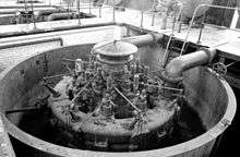
Humphrey's pump consists of a large U-shaped tube, filled with water. One end is sealed by a heavy cast iron 'combustion head'. The combustion head contains the inlet and exhaust valves, the ignition source and withstands the pressure of the combustion chamber. Water enters the pump through sprung inlet valves below the combustion chamber. A distinctive feature of the Humphrey pump, compared to others, is that the water only has to flow through this single set of valves: there are no non-return outlet valves, only the inertia of the delivered water within the outlet pipe is used to control its flow. As there are no delivery valves opening and closing suddenly, the water flow changes smoothly, avoiding water hammer and the usual problems for this type of pump.[1][5]
Combustible gas, mixed with air, is supplied into the combustion chamber and then fired by an electric spark. The force of the expanding gas drives water downwards from the combustion chamber and accelerates it along the delivery pipe. Once the chamber pressure drops to that of the inlet water, the delivered water is no longer being accelerated but the large mass of water in the long pipe continues to flow by its own inertia. This reduces the pressure in the chamber below atmospheric, which causes the inlet air and gas valves to open, drawing in fresh air as a scavenging effect. As the water begins to flow back down the U, this increases the chamber pressure and causes the exhaust valves to open.
The engines were fuelled by producer gas, generated on site. This could be produced from wood, as at Cobdogla, or from coal.
Ignition was electric, by spark plug. As there was no moving shaft on which to mount a magneto, the high tension current was supplied by a trembler coil.
Four-stroke and two-stroke cycles
The Humphrey pump could operate with either a four-stroke or two-stroke cycle.[2] Their normal operation was a four-stroke cycle. This required mechanical interlocks to the inlet valves, so that the exhaust and scavenge valves open once during the cycle to allow scavenging of the exhaust, but not during the compression cycle afterwards.[6] A two-stroke cycle was also possible, if adequate scavenging could be achieved. The air trapped within the combustion chamber of a Humphrey pump has two roles: both for combustion and also as an air spring to maintain the oscillating water column. As this spring action involves a large volume of air, relative to the minimal air needed for combustion, the air cools easily to below the ignition temperature to pre-ignite the next charge. There would still be a risk of inefficient four-stroking though, unless the scavenging is effective enough to sweep out the previous exhaust gases. This was done by using a tall, thin combustion chamber so that the combustion air remained roughly isolated from the majority of the chamber's air and so was scavenged through the exhaust valves first. There was no separate scavenge air valve.[7]
The two-stroke offered efficiency advantages. As the charge compression was carried out by the more powerful first compression stroke, a higher compression ratio was achieved, giving better efficiency.[7] Despite this, the two-stroke design does not appear to have been used commercially.
Installed pumps
Few completed installations of Humphrey pumps are known and described:
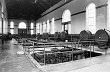
King George V Reservoir, near Chingford in East London, had four Humphrey pumps installed when the pumping station was first constructed in 1912.[8][9][10] Each pump was capable of pumping 40,000,000 gallons of water per day. A fifth, smaller, pump was added later.[2] These were built by Beardmore's of Glasgow.
A single 66" diameter pump was installed at Del Rio, Texas in 1914.[11] This was constructed by the Humphrey Gas Pump Co. of Syracuse, NY, who had licensed the Humphrey patents.
A very large drainage and irrigation plant for Egypt was also considered in 1914.[12] Construction of this was disrupted, owing to the outbreak of World War I. It was originally to use eighteen pumps, each delivering 100,000,000 gallons per day to a head of 20 feet.[1][13] Each pump chamber was to be 8 ft 8 in in diameter and 14 ft high. Final construction used ten pumps, five by Beardmore's and five by the Italian division of Brown Boveri.[12]
Two pumps were installed at Cobdogla, on the Murray River in Australia, from 1923. These were constructed by Beardmore's in Glasgow and shipped out to Australia for assembly.[14][15]
Surviving examples
The Chingford pumps were replaced by electric pumps in the 1970s, although three of the pumps remain in situ.[16]
Cobdogla's pumps ran from 1927 to 1965. In 1985 one was restored as a working example and was awarded an IMechE Engineering Heritage Award.[17]
A working model of a Humphrey pump has recently been constructed and demonstrated at various open days at UK museums.[16]
Similar pumps
A similar pump, the Joy pump, was also described at around the same time. This was much smaller, around six inches in diameter rather than six feet, and also had much smaller water pipe connections to it. This reduced water mass also reduced the compression ration available in the combustion chamber, leading to reduced efficiency. The pump's ability to work with a suction lift of a few feet, rather than needing to be submerged like the Humphrey pump, was a convenience though. This pump was thought to have some application for small-scale or portable tasks, where its convenience outweighed efficiency.[18]
See also
Notes
- ↑ An important sub-group of fluidynes pump liquid in a continuous loop circuit, as a means of heat transfer.
References
- 1 2 3 4 Wimperis, H.E. (1915). "The Gas Engine". The Internal Combustion Engine (2nd ed.). London: Constable & Company. pp. 113–117.
- 1 2 3 4 McLaughlan, James Ivey (1931). "The Humphrey Pump and the Installation of Two Sixty-Six Inch Units at Cobdogla, River Murray" (PDF). Trans. Inst. Engineers of Australia. XII: 413–426.
- ↑ Humphrey, Herbert A. (19 November 1909). "An Internal-Combustion Pump, and other applications of a new Principal". Proc. IMechE.
- ↑ "The Humphrey Pump at the Brussels Exhibition". Engineering. 22 July 1910.
- ↑ Kennedy, Rankin (1912). The Book of Modern Engines & Power Generators. Vol V. Caxton. pp. 1–16.
- ↑ Kennedy & Modern Engines V, pp. 2,4
- 1 2 Kennedy & Modern Engines V, pp. 11–12
- ↑ "The New Reservoir at Chingford, No I". The Engineer. 14 March 1913.
- ↑ "The New Reservoir at Chingford, No II". The Engineer. 21 March 1913.
- ↑ "The New Reservoir at Chingford, No III". The Engineer. 28 March 1913.
- ↑ "A Humphrey Direct-Acting Explosion Pump for Irrigation Service at Del Rio, Texas". Engineering News. 72 (16). 15 October 1914.
- 1 2 "The Largest Pumping Plant in the World: a Great Humphrey Engine Pumping Plant for Land Drainage in Egypt". Engineering News. 72 (2). 9 July 1914.
- ↑ Internal Combustion Engineering. 24 June 1914. Missing or empty
|title=(help) - ↑ SA Water. "Cobdogla Humphrey Pumps". Flickr.
- ↑ "Preparing to Instal Gigantic Humphrey Pump.". Murray Pioneer and Australian River Record (Renmark, SA : 1913 - 1942). Renmark, SA: National Library of Australia. 21 December 1923. p. 5. Retrieved 30 April 2014.
- 1 2 Reconstructing a working model Humphrey Pump
- ↑ "The Humphrey Pump".
- ↑ Kennedy & Modern Engines V, pp. 15–16
Further reading
| Wikimedia Commons has media related to Humphrey Pumps. |
- P.D.Dunn, N.G.Joyce, D.J.Fulford, "The Humphrey Pump", A Report to the Ministry of Overseas Development, Department of Engineering and Cybernetics, University of Reading. January 1977.
- Denis Smith, "The Humphrey Pump and its Inventor", Transactions of the Newcomen Society, Volume 43 (1970) 067-092.