Control system

A control system is a device, or set of devices, that manages, commands, directs or regulates the behaviour of other devices or systems. They can range from a home heating controller using a thermostat controlling a boiler to large Industrial control systems which are used for controlling processes or machines.
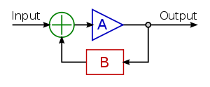
In the most common form, the feedback control system it is desired to control a process, called the plant, so its output follows a control signal, which may be a fixed or changing value. The control system compares the output of the plant to the control signal, and applies the difference as an error signal to bring the output of the plant closer to the control signal.
Overview
The term "control system" may be applied to the essentially manual controls that allow an operator, for example, to close and open a hydraulic press, perhaps including logic so that it cannot be moved unless safety guards are in place.
An automatic sequential control system may trigger a series of mechanical actuators in the correct sequence to perform a task. For example, various electric and pneumatic transducers may fold and glue a cardboard box, fill it with product and then seal it in an automatic packaging machine. Programmable logic controllers are used in many cases such as this, but several alternative technologies exist.
In the case of linear feedback systems, a control loop, including sensors, control algorithms and actuators, is arranged in such a fashion as to try to regulate a variable at a setpoint or reference value. An example of this may increase the fuel supply to a furnace when a measured temperature drops. PID controllers are common and effective in cases such as this. Control systems that include some sensing of the results they are trying to achieve are making use of feedback and so can, to some extent, adapt to varying circumstances. Open-loop control systems do not make use of feedback, and run only in pre-arranged ways.
Open-loop and closed-loop control
There are two common classes of control systems, open loop control systems, and closed loop control systems.
In an open loop control system, the control action from the controller is independent of the "process output". A good example of this is a central heating boiler controlled only by a timer, so that heat is applied for a constant time, regardless of the temperature of the building. (The control action is the switching on/off of the boiler. The process output is the building temperature).
In a closed loop control system, the control action from the controller is dependent on the process output. In the case of the boiler analogy this would include a termperature thermostat to monitor the building temperature, and thereby feed back a signal to ensure the controller maintains the temperature set on the thermostat.
A closed loop controller therefore has a feedback loop which ensures the controller exerts a control action to give a process output the same as the "Reference input" or "set point". For this reason, closed loop controllers are also called feedback controllers.[1]
Logic control

Logic control systems for industrial and commercial machinery were historically implemented at mains voltage using interconnected relays, designed using ladder logic. Today, most such systems are constructed with programmable logic controllers (PLCs) or microcontrollers. The notation of ladder logic is still in use as a programming idiom for PLCs.[2]
Logic controllers may respond to switches, light sensors, pressure switches, etc., and can cause the machinery to start and stop various operations. Logic systems are used to sequence mechanical operations in many applications. PLC software can be written in many different ways – ladder diagrams, SFC – sequential function charts or in language terms known as statement lists.[3]
Examples include elevators, washing machines and other systems with interrelated stop-go operations.
Logic systems are quite easy to design, and can handle very complex operations. Some aspects of logic system design make use of Boolean logic.
On–off control
A thermostat is a simple negative feedback controller: when the temperature (the "process variable" or PV) goes below a set point (SP), the heater is switched on. Another example could be a pressure switch on an air compressor. When the pressure (PV) drops below the threshold (SP), the pump is powered. Refrigerators and vacuum pumps contain similar mechanisms operating in reverse, but still providing negative feedback to correct errors.
Simple on–off feedback control systems like these are cheap and effective. In some cases, like the simple compressor example, they may represent a good design choice.
In most applications of on–off feedback control, some consideration needs to be given to other costs, such as wear and tear of control valves and perhaps other start-up costs when power is reapplied each time the PV drops. Therefore, practical on–off control systems are designed to include hysteresis which acts as a deadband, a region around the setpoint value in which no control action occurs. The width of deadband may be adjustable or programmable.
Linear control
Linear control systems use linear negative feedback to produce a control signal mathematically based on other variables, with a view to maintain the controlled process within an acceptable operating range.
The output from a linear control system into the controlled process may be in the form of a directly variable signal, such as a valve that may be 0 or 100% open or anywhere in between. Sometimes this is not feasible and so, after calculating the current required corrective signal, a linear control system may repeatedly switch an actuator, such as a pump, motor or heater, fully on and then fully off again, regulating the duty cycle using pulse-width modulation.
Proportional control


When controlling the temperature of an industrial furnace, it is usually better to control the opening of the fuel valve in proportion to the current needs of the furnace. This helps avoid thermal shocks and applies heat more effectively.
Proportional negative-feedback systems are based on the difference between the required set point (SP) and process value (PV). This difference is called the error. Power is applied in direct proportion to the current measured error, in the correct sense so as to tend to reduce the error and therefore avoid positive feedback. The amount of corrective action that is applied for a given error is set by the gain or sensitivity of the control system.
At low gains, only a small corrective action is applied when errors are detected. The system may be safe and stable, but may be sluggish in response to changing conditions. Errors will remain uncorrected for relatively long periods of time and the system is over-damped. If the proportional gain is increased, such systems become more responsive and errors are dealt with more quickly. There is an optimal value for the gain setting when the overall system is said to be critically damped. Increases in loop gain beyond this point lead to oscillations in the PV and such a system is under-damped.
In real systems, there are practical limits to the range of the manipulated variable (MV). For example, a heater can be off or fully on, or a valve can be closed or fully open. Adjustments to the gain simultaneously alter the range of error values over which the MV is between these limits. The width of this range, in units of the error variable and therefore of the PV, is called the proportional band (PB). While the gain is useful in mathematical treatments, the proportional band is often used in practical situations. They both refer to the same thing, but the PB has an inverse relationship to gain – higher gains result in narrower PBs, and vice versa.
Under-damped furnace example
In the furnace example, suppose the temperature is increasing towards a set point at which, say, 50% of the available power will be required for steady-state. At low temperatures, 100% of available power is applied. When the process value (PV) is within, say 10° of the SP the heat input begins to be reduced by the proportional controller (note that this implies a 20° proportional band (PB) from full to no power input, evenly spread around the setpoint value). At the setpoint the controller will be applying 50% power as required, but stray stored heat within the heater sub-system and in the walls of the furnace will keep the measured temperature rising beyond what is required. At 10° above SP, we reach the top of the proportional band (PB) and no power is applied, but the temperature may continue to rise even further before beginning to fall back. Eventually as the PV falls back into the PB, heat is applied again, but now the heater and the furnace walls are too cool and the temperature falls too low before its fall is arrested, so that the oscillations continue.
Over-damped furnace example
The temperature oscillations that an under-damped furnace control system produces are unacceptable for many reasons, including the waste of fuel and time (each oscillation cycle may take many minutes), as well as the likelihood of seriously overheating both the furnace and its contents.
Suppose that the gain of the control system is reduced drastically and it is restarted. As the temperature approaches, say 30° below SP (60° proportional band (PB)), the heat input begins to be reduced, the rate of heating of the furnace has time to slow and, as the heat is still further reduced, it eventually is brought up to set point, just as 50% power input is reached and the furnace is operating as required. There was some wasted time while the furnace crept to its final temperature using only 52% then 51% of available power, but at least no harm was done. By carefully increasing the gain (i.e. reducing the width of the PB) this over-damped and sluggish behavior can be improved until the system is critically damped for this SP temperature. Doing this is known as 'tuning' the control system. A well-tuned proportional furnace temperature control system will usually be more effective than on-off control, but will still respond more slowly than the furnace could under skillful manual control.
PID control


Apart from sluggish performance to avoid oscillations, another problem with proportional-only control is that power application is always in direct proportion to the error. In the example above we assumed that the set temperature could be maintained with 50% power. What happens if the furnace is required in a different application where a higher set temperature will require 80% power to maintain it? If the gain was finally set to a 50° PB, then 80% power will not be applied unless the furnace is 15° below setpoint, so for this other application the operators will have to remember always to set the setpoint temperature 15° higher than actually needed. This 15° figure is not completely constant either: it will depend on the surrounding ambient temperature, as well as other factors that affect heat loss from or absorption within the furnace.
To resolve these two problems, many feedback control schemes include mathematical extensions to improve performance. The most common extensions lead to proportional-integral-derivative control, or PID control.
Derivative action
The derivative part is concerned with the rate-of-change of the error with time: If the measured variable approaches the setpoint rapidly, then the actuator is backed off early to allow it to coast to the required level; conversely if the measured value begins to move rapidly away from the setpoint, extra effort is applied—in proportion to that rapidity—to try to maintain it.
Derivative action makes a control system behave much more intelligently. On control systems like the tuning of the temperature of a furnace, or perhaps the motion-control of a heavy item like a gun or camera on a moving vehicle, the derivative action of a well-tuned PID controller can allow it to reach and maintain a setpoint better than most skilled human operators could.
If derivative action is over-applied, it can lead to oscillations too. An example would be a PV that increased rapidly towards SP, then halted early and seemed to "shy away" from the setpoint before rising towards it again.
Integral action

The integral term magnifies the effect of long-term steady-state errors, applying ever-increasing effort until they reduce to zero. In the example of the furnace above working at various temperatures, if the heat being applied does not bring the furnace up to setpoint, for whatever reason, integral action increasingly moves the proportional band relative to the setpoint until the PV error is reduced to zero and the setpoint is achieved.
Ramp UP % per minute
Some controllers include the option to limit the "ramp up % per minute". This option can be very helpful in stabilizing small boilers (3 MBTUH), especially during the summer, during light loads. A utility boiler "unit may be required to change load at a rate of as much as 5% per minute (IEA Coal Online - 2, 2007)".[4]
Other techniques
It is possible to filter the PV or error signal. Doing so can reduce the response of the system to undesirable frequencies, to help reduce instability or oscillations. Some feedback systems will oscillate at just one frequency. By filtering out that frequency, more "stiff" feedback can be applied, making the system more responsive without shaking itself apart.
Feedback systems can be combined. In cascade control, one control loop applies control algorithms to a measured variable against a setpoint, but then provides a varying setpoint to another control loop rather than affecting process variables directly. If a system has several different measured variables to be controlled, separate control systems will be present for each of them.
Control engineering in many applications produces control systems that are more complex than PID control. Examples of such fields include fly-by-wire aircraft control systems, chemical plants, and oil refineries. Model predictive control systems are designed using specialized computer-aided-design software and empirical mathematical models of the system to be controlled.
Fuzzy logic
Fuzzy logic is an attempt to apply the easy design of logic controllers to the control of complex continuously varying systems. Basically, a measurement in a fuzzy logic system can be partly true, that is if yes is 1 and no is 0, a fuzzy measurement can be between 0 and 1.
The rules of the system are written in natural language and translated into fuzzy logic. For example, the design for a furnace would start with: "If the temperature is too high, reduce the fuel to the furnace. If the temperature is too low, increase the fuel to the furnace."
Measurements from the real world (such as the temperature of a furnace) are converted to values between 0 and 1 by seeing where they fall on a triangle. Usually, the tip of the triangle is the maximum possible value which translates to 1.
Fuzzy logic, then, modifies Boolean logic to be arithmetical. Usually the "not" operation is "output = 1 - input," the "and" operation is "output = input.1 multiplied by input.2," and "or" is "output = 1 - ((1 - input.1) multiplied by (1 - input.2))". This reduces to Boolean arithmetic if values are restricted to 0 and 1, instead of allowed to range in the unit interval [0,1].
The last step is to "defuzzify" an output. Basically, the fuzzy calculations make a value between zero and one. That number is used to select a value on a line whose slope and height converts the fuzzy value to a real-world output number. The number then controls real machinery.
If the triangles are defined correctly and rules are right the result can be a good control system.
When a robust fuzzy design is reduced into a single, quick calculation, it begins to resemble a conventional feedback loop solution and it might appear that the fuzzy design was unnecessary. However, the fuzzy logic paradigm may provide scalability for large control systems where conventional methods become unwieldy or costly to derive.
Fuzzy electronics is an electronic technology that uses fuzzy logic instead of the two-value logic more commonly used in digital electronics.
Physical implementations
Since modern small microprocessors are so cheap (often less than $1 US), it's very common to implement control systems, including feedback loops, with computers, often in an embedded system. The feedback controls are simulated by having the computer make periodic measurements and then calculate from this stream of measurements (see digital signal processing, sampled data systems).
Computers emulate logic devices by making measurements of switch inputs, calculating a logic function from these measurements and then sending the results out to electronically controlled switches.
Logic systems and feedback controllers are usually implemented with programmable logic controllers which are devices available from electrical supply houses. They include a little computer and a simplified system for programming. Most often they are programmed with personal computers.
Logic controllers have also been constructed from relays, hydraulic and pneumatic devices as well as electronics using both transistors and vacuum tubes (feedback controllers can also be constructed in this manner).
See also
- Behavior trees (artificial intelligence, robotics and control)
- Building automation
- Coefficient diagram method
- Control engineering
- Control theory
- Cybernetics
- Distributed control system
- Droop speed control
- Education and training of electrical and electronics engineers
- EPICS
- Good regulator
- Hierarchical control system
- HVAC control system
- Industrial control systems
- Motion control
- Networked control system
- Numerical control
- Perceptual control theory
- PID controller
- Process control
- Process optimization
- Programmable logic controller
- Sampled data systems
- SCADA
- VisSim
References
- ↑ "Feedback and control systems" - JJ Di Steffano, AR Stubberud, IJ Williams. Schaums outline series, McGraw-Hill 1967
- ↑ Kuphaldt, Tony R. "Chapter 6 LADDER LOGIC". Lessons In Electric Circuits -- Volume IV. Retrieved 22 September 2010.
- ↑ Brady, Ian. "Programmable logic controllers - benefits and applications" (PDF). PLCs. Retrieved 5 December 2011.
- ↑ http://www.seeei.org.il/prdFiles/2702_desc3.pdf ABB: Power Generation Energy Efficient Design of Auxiliary Systems in Fossil-Fuel Power Plants, Page 262, Section: Load Following
External links
| Wikibooks has a book on the topic of: Control Systems |
- Semiautonomous Flight Direction - Reference unmannedaircraft.org
- Control System Toolbox for design and analysis of control systems.
- Control Systems Manufacturer Design and Manufacture of control systems.
- Mathematica functions for the analysis, design, and simulation of control systems