Control valve
A control valve is a valve used to control fluid flow by varying the size of the flow passage as directed by a signal from a controller.[1] This enables the direct control of flow rate and the consequential control of process quantities such as pressure, temperature, and liquid level.
In automatic control terminology a control valve is termed a "final control element".
Operation

The opening or closing of automatic control valves is usually done by electrical, hydraulic or pneumatic actuators. Normally with a modulating valve, which can be set to any position between fully open and fully closed, valve positioners are used to ensure the valve attains the desired degree of opening.
Air-actuated valves are commonly used because of their simplicity, as they only require a compressed air supply, whereas electrically-operated valves require additional cabling and switch gear, and hydraulically-actuated valves required high pressure supply and return lines for the hydraulic fluid.
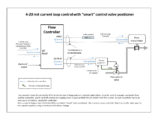
The pneumatic control signals are traditionally based on a pressure range of 3-15psi (0.2-1.0 bar), or more commonly now, an electrical signal of 4-20mA for industry, or 0-10V for HVAC systems. Electrical control now often includes a "Smart" communication signal superimposed on the 4-20mA control current, such that the health and verification of the valve position can be signalled back to the controller. The HART, Fieldbus Foundation, and Profibus are the most common protocols.
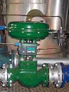
An automatic control valve consists of three main parts in which each part exist in several types and designs:
- Valve actuator - which moves the valve's modulating element, such as ball or butterfly.
- Valve positioner - Which ensures the valve has reached the desired degree of opening. This overcomes the problems of friction and wear.
- Valve body - in which the modulating element, a plug, globe, ball or butterfly, is contained.
Control action

Taking the example of an air-operated valve, there are two control actions possible:
- "Air or current to open" - The flow restriction decreases with increased control signal value.
- "Air or current to close" - The flow restriction increases with increased control signal value.
There can also be failure to safety modes:
- Air or control signal failure to close" - On failure of compressed air to the actuator, the valve closes under spring pressure or by backup power.
- Air or control signal failure to open" - On failure of compressed air to actuator, the valve opens under spring pressure or by backup power.
The modes of failure operation are requirements of the failure to safety process control specification of the plant. In the case of cooling water it may be to fail open, and the case of delivering a chemical it may be to fail closed.
Valve positioners
As the pneumatic operation of valves, compared to motorised operation, has cost and reliability advantages, pneumatic actuation is still an industry standard. To allow the construction of hybrid systems, where the 4-20 mA is generated by the controller, but enables the use of pneumatic valves, a range of current to pressure (I to P) converters are available from manufacturers. These are usually located locally to the control valve and convert 4-20 mA to 3-15 psi (or (0.2 - 1.0 bar). This signal is then fed to the valve actuator or more commonly, a pneumatic positioner. This is a dedicated controller with a pneumatic nozzle and flapper arrangement and a mechanical linkage to sense the valve actuator movement. This ensures that problems of friction are overcome and the valve control element moves to the desired position, by comparing the actual valve regulating element position against the desired value; hence the name "positioner". As a mechanical linkage is used for this, the positioner has to be mounted on the valve body. A positioner also allows the use of higher air pressures for valve actuation, which is particularly useful with cylinder type valve actuators.
With the development of cheap industrial micro-processors, "smart" valve positioners have become available since the mid-1980s and are very popular for new installations. These include an I to P converter, plus valve position and condition monitoring in an integral unit mounted on the valve body. The valve position and status are fed back over the current loop to the controller, using such as the HART protocol. This allows further verification that the valve is operating as desired.
Types of control valve bodies
A huge variety of valve types and control operation exist. However there are two main forms of action; the sliding stem and the rotary action.
The most common and versatile types of control valves are sliding-stem globe, V-notch ball, butterfly and angle types. Their popularity derives from rugged construction and the many options available that make them suitable for a variety of process applications.[2] Control valve bodies may be categorized as below:[3]
List of common types of control valve
- Sliding Stem
- Rotary
- Other
See also
References
- ↑ Instrument Society of America Standard S561.1, 1976. as reproduced in the "Fisher control valve handbook" forth edition 1977.
- ↑ Hagen, S. (2003) "Control valve technology" Plant Services
- ↑ Fisher Controls International Emerson Process Management website.
External links
- Control valve tutorials Tutorials covering the sizing, capacity and characteristics of control valves. Actuators, positioners, controllers and sensors are also discussed - Spirax Sarco
- Control Valve Handbook (4th Edition) A 297-page online book.
- Process Instrumentation (Lecture 8): Control valves Article from a University of South Australia website.
- Pressure Independent Control Valve Animation Flash animations demonstrating conventional and pressure independent control valve operation.
- Samson AG Demo Valve Sizing Software. Basic Trial valve sizing programme.
- Control Valve Sizing Calculator Control Valve Sizing Calculator to determine Cv for a valve.