X10 (industry standard)

X10 is a protocol for communication among electronic devices used for home automation (domotics). It primarily uses power line wiring for signaling and control, where the signals involve brief radio frequency bursts representing digital information. A wireless radio based protocol transport is also defined.
X10 was developed in 1975 by Pico Electronics of Glenrothes, Scotland, in order to allow remote control of home devices and appliances. It was the first general purpose domotic network technology and remains the most widely available.[1]
Although a number of higher bandwidth alternatives exist, X10 remains popular in the home environment with millions of units in use worldwide, and inexpensive availability of new components.
History
In 1970, a group of engineers started a company in Glenrothes, Scotland called Pico Electronics.[2] The company developed the first single chip calculator.[1] When calculator integrated circuit prices started to fall, Pico refocused on commercial products rather than plain ICs.
In 1974, the Pico engineers jointly developed a LP record turntable, the ADC Accutrac 4000, with Birmingham Sound Reproducers, at the time the largest manufacturer of record changers in the world. It could be programmed to play selected tracks, and could be operated by a remote control using ultrasound signals, which sparked the idea of remote control for lights and appliances. By 1975, the X10 project was conceived, so named because it was the tenth project. In 1978, X10 products started to appear in RadioShack and Sears stores. Together with BSR a partnership was formed, with the name X10 Ltd. At that time the system consisted of a 16 channel command console, a lamp module, and an appliance module. Soon after came the wall switch module and the first X10 timer.
In the 1980s, the CP-290 computer interface was released. Software for the interface runs on the Commodore 64, Apple II, Macintosh, MS-DOS, and MS-Windows.
In 1985, BSR went out of business, and X10 (USA) Inc. was formed. In the early 1990s, the consumer market was divided into two main categories, the ultra-high-end with a budget at US$100,000 and the mass market with budgets at US$2,000 to US$35,000. CEBus (1984) and LonWorks (1991) were attempts to improve reliability and replace X10.
Power line carrier control overview
Household electrical wiring which powers lights and appliances is used to send digital data between X10 devices. This data is encoded onto a 120 kHz carrier which is transmitted as bursts during the relatively quiet zero crossings of the 50 or 60 Hz AC alternating current waveform. One bit is transmitted at each zero crossing.[3]
The digital data consists of an address and a command sent from a controller to a controlled device. More advanced controllers can also query equally advanced devices to respond with their status. This status may be as simple as "off" or "on", or the current dimming level, or even the temperature or other sensor reading. Devices usually plug into the wall where a lamp, television, or other household appliance plugs in; however some built-in controllers are also available for wall switches and ceiling fixtures.
The relatively high-frequency carrier wave carrying the signal cannot pass through a power transformer or across the phases of a multiphase system. For split phase systems, the signal can be passively coupled from phase-to-phase using a passive capacitor, but for three phase systems or where the capacitor provides insufficient coupling, an active X10 repeater can be used. To allow signals to be coupled across phases and still match each phase's zero crossing point, each bit is transmitted three times in each half cycle, offset by 1/6 cycle.
It may also be desirable to block X10 signals from leaving the local area so, for example, the X10 controls in one house do not interfere with the X10 controls in a neighboring house. In this situation, inductive filters can be used to attenuate the X10 signals coming into or going out of the local area.
Protocol
Whether using power line or radio communications, packets transmitted using the X10 control protocol consist of a four bit house code followed by one or more four bit unit codes, finally followed by a four bit command. For the convenience of users configuring a system, the four bit house code is selected as a letter from A through P while the four bit unit code is a number 1 through 16.
When the system is installed, each controlled device is configured to respond to one of the 256 possible addresses (16 house codes × 16 unit codes); each device reacts to commands specifically addressed to it, or possibly to several broadcast commands.
The protocol may transmit a message that says "select code A3", followed by "turn on", which commands unit "A3" to turn on its device. Several units can be addressed before giving the command, allowing a command to affect several units simultaneously. For example, "select A3", "select A15", "select A4", and finally, "turn on", causes units A3, A4, and A15 to all turn on.
Note that there is no restriction that prevents using more than one house code within a single house. The "all lights on" command and "all units off" commands will only affect a single house code, so an installation using multiple house codes effectively has the devices divided into separate zones.
One way vs two way
Inexpensive X10 devices only receive commands and do not acknowledge their status to the rest of the network. Two-way controller devices allow for a more robust network but cost two to four times more and require two-way X10 devices.[4]
List of X10 commands
| Code | Function | Description | One Way | Two Way |
|---|---|---|---|---|
| 0 0 0 0 | All units off | Switch off all devices with the house code indicated in the message | X | |
| 0 0 0 1 | All lights on | Switches on all lighting devices (with the ability to control brightness) | X | |
| 0 1 1 0 | All lights off | Switches off all lighting devices | X | |
| 0 0 1 0 | On | Switches on a device | X | |
| 0 0 1 1 | Off | Switches off a device | X | |
| 0 1 0 0 | Dim | Reduces the light intensity | X | |
| 0 1 0 1 | Bright | Increases the light intensity | X | |
| 0 1 1 1 | Extended code | Extension code | X | |
| 1 0 0 0 | Hail request | Requests a response from the device(s) with the house code indicated in the message | X | |
| 1 0 0 1 | Hail acknowledge | Response to the previous command | X | |
| 1 0 1 0 | Pre-set dim | Allows the selection of two predefined levels of light intensity | X | |
| 1 1 0 1 | Status is on | Response to the Status Request indicating that the device is switched on | X | |
| 1 1 1 0 | Status is off | Response indicating that the device is switched off | X | |
| 1 1 1 1 | Status request | Request requiring the status of a device | X |
Physical layer details
In the 60 Hz AC current flow, a bit value of one is represented by a 1 millisecond burst of 120 kHz at the zero crossing point (nominally 0°, but within 200 microseconds of the zero crossing point), immediately followed by the absence of a pulse. A zero value is represented by the absence of 120 kHz at the zero crossing point (pulse), immediately followed by the presence of a pulse. All messages are sent twice to reduce false signaling. After allowing for retransmission, line control, etc., data rates are around 20 bit/s, making X10 data transmission so slow that the technology is confined to turning devices on and off or other very simple operations.
In order to provide a predictable start point, every data frame transmitted always begin with a start code of 1110. Immediately after the start code, a house code (A–P) appears, and after the letter code comes a function code. Function codes may specify a unit number code (1–16) or a command code, the selection between the two modes being determined by the last bit where 0=unit number and 1=command. One start code, one letter code, and one function code is known as an X10 frame and represent the minimum components of a valid X10 data packet.
Each frame is sent twice in succession to make sure the receivers understand it over any power line noise for purposes of redundancy, reliability, and to accommodate line repeaters.
Whenever the data changes from one address to another address, from an address to a command, or from one command to another command, the data frames must be separated by at least 6 clear zero crossings (or "000000"). The sequence of six zeros resets the device decoder hardware.
Later developments (1997) of hardware are improvements of the native X10 hardware. In Europe (2001) for the 230 VAC 50 Hz market. All improved products use the same X10 protocol and are compatible.
RF protocol
To allow for wireless keypads, remote switches, motion sensors, et cetera, an RF protocol is also defined. X10 wireless devices send data packets that are nearly identical to the NEC IR protocol used by many IR remotes, and a radio receiver then provides a bridge which translates these radio packets to ordinary X10 power line control packets. The wireless protocol operates at a frequency of 310 MHz in the U.S. and 433.92 MHz in European systems.
The devices available using the radio protocol include:
- Keypad controllers ("clickers")
- Keychain controllers that can control one to four X10 devices
- Burglar alarm modules that can transmit sensor data
- Passive infrared switches to control lighting and X-10 chimes
- Non-passive information bursts
Hardware support
Device modules

Depending on the load that is to be controlled, different modules must be used. For incandescent lamp loads, a lamp module or wall switch module can be used. These modules switch the power using a TRIAC solid state switch and are also capable of dimming the lamp load. Lamp modules are almost silent in operation, and generally rated to control loads ranging from approximately 40 to 500 watts.
For loads other than incandescent lamps, such as fluorescent lamps, high-intensity discharge lamps, and electrical home appliances, the triac-based electronic switching in the lamp module is unsuitable and an appliance module must be used instead. These modules switch the power using an impulse relay. In the U.S., these modules are generally rated to control loads up to 15 amperes (1800 watts at 120V).
Many device modules offer a feature called local control. If the module is switched off, operating the power switch on the lamp or appliance will cause the module to turn on. In this way, a lamp can still be lit or a coffee pot turned on without the need to use an X10 controller. Wall switch modules may not offer this feature.
Some wall switch modules offer a feature called local dimming. Ordinarily, the local push button of a wall switch module simply offers on/off control with no possibility of locally dimming the controlled lamp. If local dimming is offered, holding down the push button will cause the lamp to cycle through its brightness range.
Higher end modules have more advanced features such as programmable on levels, customizable fade rates, the ability to transmit commands when used (referred to as 2-way devices), and scene support.
There are sensor modules that sense and report temperature, light, infra-red, motion, or contact openings and closures. Device modules include thermostats, audible alarms and controllers for low voltage switches.
Controllers

X10 controllers range from extremely simple to very sophisticated.
The simplest controllers are arranged to control four X10 devices at four sequential addresses (1–4 or 5–8). The controllers typically contain the following buttons:
- Unit 1 on/off
- Unit 2 on/off
- Unit 3 on/off
- Unit 4 on/off
- Brighten/dim (last selected unit)
- All lights on/all units off
More sophisticated controllers can control more units and/or incorporate timers that perform preprogrammed functions at specific times each day. Units are also available that use passive infrared motion detectors or photocells to turn lights on and off based on external conditions.
Finally, very sophisticated units are available that can be fully programmed or, like the X10 Firecracker, use a program running in an external computer. These systems can execute many different timed events, respond to external sensors, and execute, with the press of a single button, an entire scene, turning lights on, establishing brightness levels, and so on. Control programs are available for computers running Microsoft Windows, Apple's Macintosh, Linux and FreeBSD operating systems.
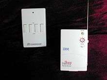
Burglar alarm systems are also available. These systems contain door/window sensors, as well as motion sensors that use a coded radio frequency (RF) signal to identify when they are tripped or just to routinely check-in and give a heart-beat signal to show that the system is still active. Users can arm and disarm their system via several different remote controls that also use a coded RF signal to ensure security. When an alarm is triggered the console will make an outbound telephone call with a recorded message. The console will also use X10 protocols to flash lights when an alarm has been triggered while the security console sounds an external siren. Using X10 protocols, signals will also be sent to remote sirens for additional security.
Bridges
There are bridges to translate X10 to other domotic standards (e.g., KNX). ioBridge can be used to translate the X10 protocol to a web service API via the X10 PSC04 Powerline Interface Module. The magDomus home controller from magnocomp allows interconnection and inter-operation between most home automation technologies.
Limitations
Compatibility
Solid-state switches used in X10 controls pass a very small leakage current. Compact fluorescent lamps may display nuisance blinking when switched off; CFL manufacturers recommend against controlling lamps with solid-state timers or remote controls.
Some X10 controllers with triac solid-state outputs may not work well or at all with low power devices (below 50 watts) or devices like fluorescent bulbs that do not present resistive loads, due to the small leakage current of the device and any protective filtering around the triac. Use of an appliance module, which has a relay with metallic contacts, rather than a lamp module, may resolve this problem. Not all devices can be used on a dimmer. Fluorescent lamps are not dimmable with incandescent lamp dimmers; certain models of compact fluorescent lamps are dimmable but cost more. Motorized appliances such as fans, etc. generally will not operate as expected on a dimmer.
Wiring and interfering sources
One problem with X10 is excessive attenuation of signals between the two live conductors in the 3-wire 120/240 volt system used in typical North American residential construction. Signals from a transmitter on one live conductor may not propagate through the high impedance of the distribution transformer winding to the other live conductor. Often, there's simply no reliable path to allow the X10 signals to propagate from one transformer leg wire to the other; this failure may come and go as large 240 volt devices such as stoves or dryers are turned on and off. (When turned on, such devices provide a low-impedance bridge for the X10 signals between the two leg wires.) This problem can be permanently overcome by installing a capacitor between the leg wires as a path for the X10 signals; manufacturers commonly sell signal couplers that plug into 240 volt sockets that perform this function. More sophisticated installations install an active repeater device between the legs, while others combine signal amplifiers with a coupling device. A repeater is also needed for inter-phase communication in homes with three-phase electric power. In many countries outside North America, entire houses are typically wired from a single 240 volt single-phase wire, so this problem does not occur.
Television receivers or household wireless devices may cause spurious "off" or "on" signals. Noise filtering (as installed on computers as well as many modern appliances) may help keep external noise out of X10 signals, but noise filters not designed for X10 may also attenuate X10 signals traveling on the branch circuit to which the appliance is connected.
Certain types of power supplies used in modern electronic equipment, such as computers, television receivers and satellite receivers, attenuate passing X10 signals by providing a low impedance path to high frequency signals. Typically, the capacitors used on the inputs to these power supplies short the X10 signal from line to neutral, suppressing any hope of X10 control on the circuit near that device. Filters are available that will block the X10 signals from ever reaching such devices; plugging offending devices into such filters can cure mysterious X10 intermittent failures.
Having a backup power supply or standby power supply such as used with computers or other electronic devices can totally kill that leg in a household installation because of the filtering used in the power supply.
Commands getting lost
X10 signals can only be transmitted one command at a time, first by addressing the device to control, and then sending an operation for that device to perform. If two X10 signals are transmitted at the same time they may collide or interleave, leading to commands that either cannot be decoded or that trigger incorrect operations. The CM15A and RR501 Transceiver can avoid these signal collisions that can sometimes occur with other models.
Relatively slow
The X10 protocol is slow. It takes roughly three quarters of a second to transmit a device address and a command. While generally not noticeable when using a tabletop controller, it becomes a noticeable problem when using 2-way switches or when utilizing some sort of computerized controller. The apparent delay can be lessened somewhat by using slower device dim rates. With more advanced modules another option is to use group control (lighting scene) extended commands. These allow adjusting several modules at once by a single command.
Limited functionality
X10 protocol does support more advanced control over the dimming speed, direct dim level setting and group control (scene settings). This is done via extended message set, which is an official part of X10 standard. However support for all extended messages is not mandatory, and many cheaper modules implement only the basic message set. These require adjusting each lighting circuit one after the other, which can be visually unappealing and also very slow.
Interference and lack of encryption
The standard X10 power line and RF protocols lack support for encryption, and can only address 256 devices. Unfiltered power line signals from close neighbors using the same X10 device addresses may interfere with each other. Interfering RF wireless signals may similarly be received, with it being easy for anyone nearby with an X10 RF remote to wittingly or unwittingly cause mayhem if an RF to power line device is being used on a premises.
References
- 1 2 Rye, Dave (October 1999). "My Life at X10". AV and Automation Industry eMagazine. AV and Automation Industry eMagazine. Retrieved October 8, 2014.
- ↑ The history of X10
- ↑ "How X10 Works". www.smarthomeusa.com. Retrieved 2016-03-08.
- ↑ "One way vs two way modules - Home Technology Information - hmtech.info". automation.hmtech.info. Retrieved 2016-03-08.
External links
- X10 Knowledge Base
- X10 Schematics and Modifications
- X10 Protocol, X-10 PL513/TW523 Protocol Technical Note
- Digital X-10, Which One Should I Use?.
