Willans engine
.jpg)
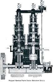
The Willans engine was a high-speed stationary steam engine used for electricity generation around the start of the 20th century.
Willans' engine was one of the best-known examples of the steeple compound engine.[1] These were double- or triple-expansion compound engines, with the unusual features of single-acting cylinders and a central spindle valve shared between all the cylinders of that spindle.[lower-roman 1][3][4] The cylinders are arranged as tandem compounds, with high- and low-pressure cylinders mounted on the same vertical shaft. This vertical arrangement of the steeple compound gives a compact floor layout for an engine of such power.
Willans engines were not the first high-speed engines for electricity generation, but they were soon adopted to become the predominant type in service.[5]
Application
The engines were developed by Peter W. Willans and Mark Robinson at Thames Ditton, primarily for the increasing market in electrical generation. In 1884 they were granted a patent for the central valve principle.[5][6]
By the 1890s, more of the Willans type were in service for electricity generation than any other type.[5][7] As with other high-speed steam engines, the need was for a steam engine that ran at sufficiently high speeds to drive dynamos directly and also that had accurate speed regulation under changing load, so as to maintain the correct voltage. Maintaining the correct frequency for AC systems was even more important, but AC systems tended to favour slow-speed engines with large flywheels, rather than the high-speed engines used for DC.[8]
Willans engines were also used for powering textile mills, although as many mills had been built by this date, the longer-established cross-compound Corliss and drop-valve engines are better known in this application. The Willans engine, its low inertia and accurate speed control made it highly suitable for mill work. The constant shaft speed it delivered, even under a varying load, was considered to improve spinning quality and reduced the number of ends broken by shock loads.[9][10]
Operation
Single-acting operation
The Willans engine was single-acting; steam pressure was only applied to the upper surface of the pistons. This was a common feature of high-speed engines at this time, in a measure to reduce knocking and increased wear, thus permitting higher operating speeds.[3] The principle was that in a single-acting engine the forces on the connecting rod and its bearings always act to compress the rod, rather than reversing direction twice in every revolution, as for the double-acting engine.[11] The lower bearing brasses, which carried a load only during starting, were smaller than the crankpin and the main working brasses above. Although single-acting engines produce only half the power of an equivalent double-acting engine, or else must run at twice their speed, this reduced knocking could allow them to run more than twice as fast.
Air cushion
In the conventional double-acting engine, residual steam was trapped in the exhausting cylinder after the valve closed and compressed. This compressed steam has a cushioning effect and acts to brake the piston at the end of stroke.[lower-roman 2] In the single-acting engine there is no similar effect at the end of the power stroke. This had previously been a limitation on the operating speed of single-acting engines.
In the Willans engine, cushioning at the end of stroke was provided by an additional air cylinder below the others. The air piston also acted as a trunk guide. During the upward stroke, inertia of the engine continues its movement upwards and before the next stroke begins there is otherwise nothing to retard it. The enclosed air cylinder acts as a compressed air dashpot above the trunk guide piston.[12]
Central spindle valve

The most distinctive feature of the engine was its central spindle valve. This acted as a multi-stage piston valve, controlling admission of steam into each of the compound cylinders. Unusually the valve worked within the hollow piston rod or trunk, rather than in the cylinder block or valvechest. This hollow piston rod linked all of the cylinders and was machined with ports.[13]
The valvegear actuating the valve was very simple. Each piston had two parallel connecting rods, working on separated crankpin journals between the same crank webs. An eccentric between the two crankpins drove the centrally-mounted valve spindle by another short connecting rod. Because of the need to allow the valve rod to pass through between them, the piston had two overhung stub gudgeon pins, rather than a single through pin.[13]
Inlet steam was supplied to the top of the piston rod trunk through distinctive domed caps. If the engine was intended for a fixed cutoff, the inlet steam was controlled solely by the valve and trunk. Where variable cutoff was to be used, this was achieved very simply by a rotating collar with angled ports that overlapped the ports in the trunk and so controlled their timing.[14]
Lubrication
Lubrication of the Willans engine was by splash from an enclosed crankcase. This was filled with a mixture of oil and water.[14] Excess water from condensate was drained out of the crankcase as it accumulated, but the engines did not have the separated glands between the cylinder and crankcase, with a drainage space between them, that were used by the Carel, Belliss and Morcom, or Alley & MacLellan (later Sentinel) engines.[15]
Withdrawal
Willans engines gradually fell from use post-World War I, for two reasons.
Firstly, Belliss and Morcom further developed the high-speed engine. Their invention in 1890 of the oil pump and forced lubrication system solved the problem of the bearing rattling under a reversing load.[16][17] This allowed them to produce double-acting engines that were more compact than single-acting. Where a single cylinder engine could replace a small twin cylinder engine, this was also a useful cost saving. Although some steam generating sets remained in use well into the 1980s,[lower-roman 3] these were almost all of the Belliss and Morcom double-acting type.
Secondly, the growth of electricity generation and the development of the National Grid favoured fewer, larger generating stations, rather than the small local stations of the first generation. These large plants could more efficiently use large steam turbines and could afford the complicated high-superheat water-tube boilers used with them.
Similar engines
Carel's engine
The Carel engine, built by SA des Moteurs á Grand Vitesse. Brevet Carel's of Sclessin-Liège, Belgium, was very similar to the Willans.[18] It used a similar layout of paired cylinders, in numbers from two to eight. It too was built for double- and triple-expansion. Like the Willans engine it used single-acting cylinders and also used the Willans air-cushion trunk guide. It differed in the design of its valves, as these were rotary. Each pair of cylinders had a shared rotary valve between them, driven by a half-speed bevel gear. Like the Paget locomotive, the valves were of cast-iron and ran in a phosphor bronze sleeve within the cylinder.[19] As the valve and cylinders must operate in phase,[lower-roman 4] the ports are duplicated. The advantage overall is a reduction in linear valve speed. Such rotary valves were often tried at this period, yet rarely successfully. Lubrication was difficult at this time and superheating was limited, if the valves were not to seize.[18][lower-roman 5]
Paxman's Peache's Patent engine
The 'Peache Patent' engine was produced by Davey, Paxman & Co of Colchester, who built 260 of them between 1895 and 1913.[20] James Courthope Peache had previously worked for Willans & Robinson as Works Manager at the Ferry Works. He left Willans in January 1892 and in 1893 he approached James Paxman with his own design of a high-speed single-acting engine. He later returned to Willans, in 1904 becoming a Director of the company, now based in Rugby, and by 1908 became Managing Director.[20]
The Peache engine was considered as another single-acting tandem compound, although it had an unusual design of cylinder. The middle volume of the high- and low-pressure cylinders was in common, without the usual gland to isolate them.[20] The high-pressure piston acts downwards and the low-pressure acts upwards. The space between the pistons, referred to as the 'controlling cylinder' is partially filled with steam tapped from the high-pressure cylinder. As this is compressed when the pistons move upwards, it acts in a similar manner to the air-cushion of the Willans.[11]
Piston valves behind the cylinders were worked by a form of radial valvegear, driven by the connecting rod.[20]
Unusually for a steam engine, but somewhat advantageously for a single-acting engine, the Peache was a desaxe engine. By slightly offsetting the crankshaft and piston axis, the crosshead forces remained towards the rear of the engine, throughout the operating cycle.[20] Like the single-acting principle itself, this constant direction of forces helped to reduce vibration and wear.[20]
Survivors

Few examples of these large electrical generation engines survive, including the Willans. A few of the examples still survive, including a very small one in the Science Museum. This is a 10 kW engine at 450 rpm and is displayed alongside its original bipolar dynamo. A single cylinder from a larger engine is also displayed, sectioned (illus.).
A three-cylinder, two-stage engine is preserved in the Science and Tecnic Museum of Catalonia (mNACTEC).[21]
Notes
| Wikimedia Commons has media related to Willans steam engines. |
- ↑ I.e. one valve supplied all pistons in a vertical column. In contrast, Bellis (and others) produced a well-known design where a single piston valve was shared between adjacent cylinders horizontally.[2]
- ↑ This recompression was an important factor in the efficiency of the uniflow engine.
- ↑ Mostly in hospitals, where there was already substantial steam plant for heating and reliable backup electricity generators were needed.
- ↑ This is like an internal combustion two-stroke engine, rather than the four-stroke engine that also applies a half-speed reduction gear to its camshaft.
- ↑ As indeed happened to the Paget locomotive.
References
- ↑ Hills, Richard L. (1989). Power from Steam. Cambridge University Press. pp. 215–219. ISBN 0-521-45834-X.
- ↑ Hills, Power from Steam, p. 218.
- 1 2 Kennedy, Rankin (1912 edition of 1905 book.). "I. Steam Engine Parts and Accessories". Valve Gearing and Governors. The Book of Modern Engines and Power Generators. Vol. IV. London: Caxton. pp. 17–19. Check date values in:
|date=(help) - ↑ Kennedy, Electrical Installations, pp. 69–73.
- 1 2 3 "New steam engine designs". Science Museum.
- ↑ GB 13769, Peter W. Willans, issued 17 October 1874
- ↑ Kennedy, Rankin (1903 edition (five volumes) of pre-1903 four volume edition.). Electrical Installations. Electrical Installations. Vol. III. London: Caxton. pp. 32–33. Check date values in:
|date=(help) - ↑ Kennedy, Electrical Installations, p. 69.
- ↑ Hills, Richard L. (1989). Power from Steam. Cambridge University Press. p. 217. ISBN 0-521-45834-X.
- ↑ The Willans Engine for Rope & Belt Driving Purposes. Rugby: Willans & Robinson Ltd. p. 8.
- 1 2 Ripper, William C. H. (1920). "Quick-Revolution Engines". Steam Engine Theory And Practice (Seventh ed.). London: Longmans, Green & Co. pp. 350–352.
- ↑ GB 4901, Peter W. Willans, issued 14 October 1882
- 1 2 Kennedy, Electrical Installations, pp. 71–72.
- 1 2 Kennedy, Electrical Installations, p. 72.
- ↑ Kennedy, Modern Engines, IV, pp. 208–215.
- ↑ "High-Speed Steam Engines.". 20 December 2005.
- ↑ Hills, Power from Steam, p. 219.
- 1 2 "High-Speed Steam Engines". Douglas Self. 20 December 2005.
- ↑ Kennedy, Modern Engines, IV, pp. 213–215.
- 1 2 3 4 5 6 Richard Carr. "Paxman "Peache Patent" Steam Engines". Paxman History.
- ↑ http://www.mnactec.cat/docs/1182326741_vapor_carbon.pdf