Anemometer
An anemometer is a device used for measuring wind speed, and is a common weather station instrument. The term is derived from the Greek word anemos, which means wind, and is used to describe any wind speed measurement instrument used in meteorology. The first known description of an anemometer was given by Leon Battista Alberti in 1450.
History
The anemometer has changed little since its development in the 15th century. Leon Battista Alberti (1404–1472) is said to have invented the first mechanical anemometer around 1450. In following centuries, numerous others, including Robert Hooke (1635–1703), developed their own versions, with some being mistakenly credited as the inventor. In 1846, John Thomas Romney Robinson (1792–1882) improved upon the design by using four hemispherical cups and mechanical wheels. In 1926, Canadian meteorologist John Patterson (January 3, 1872 – February 22, 1956) developed a three-cup anemometer, which was improved by Brevoort and Joiner in 1935. In 1991, Derek Weston added the ability to detect wind direction. In 1994, Andrews Pflitsch developed the sonic anemometer.[1]
Velocity anemometers
Cup anemometers

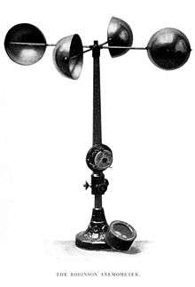
A simple type of anemometer was invented in 1845 by Dr. John Thomas Romney Robinson, of Armagh Observatory. It consisted of four hemispherical cups mounted on horizontal arms, which were mounted on a vertical shaft. The air flow past the cups in any horizontal direction turned the shaft at a rate that was proportional to the wind speed. Therefore, counting the turns of the shaft over a set time period produced a value proportional to the average wind speed for a wide range of speeds. On an anemometer with four cups, it is easy to see that since the cups are arranged symmetrically on the end of the arms, the wind always has the hollow of one cup presented to it and is blowing on the back of the cup on the opposite end of the cross.
When Robinson first designed his anemometer, he asserted that the cups moved one-third of the speed of the wind, unaffected by the cup size or arm length. This was apparently confirmed by some early independent experiments, but it was incorrect. Instead, the ratio of the speed of the wind and that of the cups, the anemometer factor, depends on the dimensions of the cups and arms, and may have a value between two and a little over three. Every previous experiment involving an anemometer had to be repeated.
The three-cup anemometer developed by the Canadian John Patterson in 1926 and subsequent cup improvements by Brevoort & Joiner of the USA in 1935 led to a cupwheel design which was linear and had an error of less than 3% up to 60 mph (97 km/h). Patterson found that each cup produced maximum torque when it was at 45° to the wind flow. The three-cup anemometer also had a more constant torque and responded more quickly to gusts than the four-cup anemometer.
The three-cup anemometer was further modified by the Australian Dr Derek Weston in 1991 to measure both wind direction and wind speed. Weston added a tag to one cup, which causes the cupwheel speed to increase and decrease as the tag moves alternately with and against the wind. Wind direction is calculated from these cyclical changes in cupwheel speed, while wind speed is determined from the average cupwheel speed.
Three-cup anemometers are currently used as the industry standard for wind resource assessment studies & practice.
Vane anemometers
One of the other forms of mechanical velocity anemometer is the vane anemometer. It may be described as a windmill or a propeller anemometer. Unlike the Robinson anemometer whose axis of rotation is vertical, the axis on the vane anemometer must be parallel to the direction of the wind and therefore horizontal. Furthermore, since the wind varies in direction and the axis has to follow its changes, a wind vane or some other contrivance to fulfill the same purpose must be employed.
A vane anemometer thus combines a propeller and a tail on the same axis to obtain accurate and precise wind speed and direction measurements from the same instrument.[2] The speed of the fan is measured by a rev counter and converted to a windspeed by an electronic chip. Hence, volumetric flowrate may be calculated if the cross-sectional area is known.
In cases where the direction of the air motion is always the same, as in ventilating shafts of mines and buildings, wind vanes known as air meters are employed, and give satisfactory results.
- Vane anemometers
-
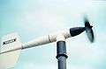
Vane style of anemometer
-
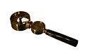
Hand-held low-speed vane anemometer
-
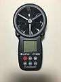
Hand-held digital anemometer

Hot-wire anemometers

Hot wire anemometers use a very fine wire (on the order of several micrometres) electrically heated to some temperature above the ambient. Air flowing past the wire cools the wire. As the electrical resistance of most metals is dependent upon the temperature of the metal (tungsten is a popular choice for hot-wires), a relationship can be obtained between the resistance of the wire and the flow speed.[3]
Several ways of implementing this exist, and hot-wire devices can be further classified as CCA (constant current anemometer), CVA (constant voltage anemometer) and CTA (constant-temperature anemometer). The voltage output from these anemometers is thus the result of some sort of circuit within the device trying to maintain the specific variable (current, voltage or temperature) constant, following Ohm's law.
Additionally, PWM (pulse-width modulation) anemometers are also used, wherein the velocity is inferred by the time length of a repeating pulse of current that brings the wire up to a specified resistance and then stops until a threshold "floor" is reached, at which time the pulse is sent again.
Hot-wire anemometers, while extremely delicate, have extremely high frequency-response and fine spatial resolution compared to other measurement methods, and as such are almost universally employed for the detailed study of turbulent flows, or any flow in which rapid velocity fluctuations are of interest.
An industrial version of the fine-wire anemometer is the thermal flow meter, which follows the same concept but uses two pins or stings to monitor the variation in temperature. The stings contain fine wires, but encasing the wires makes them much more durable and capable of accurately measuring air, gas, and emissions flow in pipes, ducts, and stacks. Industrial applications often contain dirt that will damage the classic hot-wire anemometer.
Laser Doppler anemometers
In laser Doppler velocimetry, laser Doppler anemometers use a beam of light from a laser that is divided into two beams, with one propagated out of the anemometer. Particulates (or deliberately introduced seed material) flowing along with air molecules near where the beam exits reflect, or backscatter, the light back into a detector, where it is measured relative to the original laser beam. When the particles are in great motion, they produce a Doppler shift for measuring wind speed in the laser light, which is used to calculate the speed of the particles, and therefore the air around the anemometer.[4]

Ultrasonic anemometers

Ultrasonic anemometers, first developed in the 1950s, use ultrasonic sound waves to measure wind velocity. They measure wind speed based on the time of flight of sonic pulses between pairs of transducers. Measurements from pairs of transducers can be combined to yield a measurement of velocity in 1-, 2-, or 3-dimensional flow. The spatial resolution is given by the path length between transducers, which is typically 10 to 20 cm. Ultrasonic anemometers can take measurements with very fine temporal resolution, 20 Hz or better, which makes them well suited for turbulence measurements. The lack of moving parts makes them appropriate for long-term use in exposed automated weather stations and weather buoys where the accuracy and reliability of traditional cup-and-vane anemometers are adversely affected by salty air or dust. Their main disadvantage is the distortion of the flow itself by the structure supporting the transducers, which requires a correction based upon wind tunnel measurements to minimize the effect. An international standard for this process, ISO 16622 Meteorology—Ultrasonic anemometers/thermometers—Acceptance test methods for mean wind measurements is in general circulation. Another disadvantage is lower accuracy due to precipitation, where rain drops may vary the speed of sound.
Since the speed of sound varies with temperature, and is virtually stable with pressure change, ultrasonic anemometers are also used as thermometers.
Two-dimensional (wind speed and wind direction) sonic anemometers are used in applications such as weather stations, ship navigation, wind turbines, aviation and weather buoys. Three-dimensional sonic anemometers are widely used to measure gas emissions and ecosystem fluxes using the eddy covariance method when used with fast-response infrared gas analyzers or laser-based analyzers.
Two-dimensional wind sensors are of two types:
- Two ultrasounds paths: These sensors have 4 arms. This design is more common, due to its simplicity. The disadvantage of this type of sensor is that when the wind comes in the direction of an ultrasound path, the arms disturb the airflow, reducing the accuracy of the resulting measurement.
- Three ultrasounds paths: These sensors have 3 arms. They give one path redundancy of the measurement which improves the sensor accuracy and reduces aerodynamic turbulence.
Acoustic resonance anemometers

Acoustic resonance anemometers are a more recent variant of sonic anemometer. The technology was invented by Dr Savvas Kapartis and patented (Acu-Res®) by FT Technologies in 2000.[5] Whereas conventional sonic anemometers rely on time of flight measurement, acoustic resonance sensors use resonating acoustic (ultrasonic) waves within a small purpose-built cavity in order to perform their measurement.

Built into the cavity is an array of ultrasonic transducers, which are used to create the separate standing-wave patterns at ultrasonic frequencies. As wind passes through the cavity, a change in the wave’s property occurs (phase shift). By measuring the amount of phase shift in the received signals by each transducer, and then by mathematically processing the data, the sensor is able to provide an accurate horizontal measurement of wind speed and direction.
Acoustic resonance technology enables measurement within a small cavity, the sensors therefore tend to be typically smaller in size than other ultrasonic sensors. The small size of acoustic resonance anemometers makes them physically strong and easy to heat and therefore resistant to icing. This combination of features means that they achieve high levels of data availability and are well suited to wind turbine control and to other uses that require small robust sensors such as battlefield meteorology. One issue with this sensor type is measurement accuracy when compared to a calibrated mechanical sensor. For many end uses, this weakness is compensated for by the sensor's longevity and the fact that it does not require re-calibrating once installed.
Ping-pong ball anemometers
A common anemometer for basic use is constructed from a ping-pong ball attached to a string. When the wind blows horizontally, it presses on and moves the ball; because ping-pong balls are very lightweight, they move easily in light winds. Measuring the angle between the string-ball apparatus and the vertical gives an estimate of the wind speed.
This type of anemometer is mostly used for middle-school level instruction which most students make themselves, but a similar device was also flown on Phoenix Mars Lander.[6]
Pressure anemometers

The first designs of anemometers which measure the pressure were divided into plate and tube classes.
Plate anemometers
These are the first modern anemometers. They consist of a flat plate suspended from the top so that the wind deflects the plate. In 1450, the Italian art architect Leon Battista Alberti invented the first mechanical anemometer; in 1664 it was re-invented by Robert Hooke (who is often mistakenly considered the inventor of the first anemometer). Later versions of this form consisted of a flat plate, either square or circular, which is kept normal to the wind by a wind vane. The pressure of the wind on its face is balanced by a spring. The compression of the spring determines the actual force which the wind is exerting on the plate, and this is either read off on a suitable gauge, or on a recorder. Instruments of this kind do not respond to light winds, are inaccurate for high wind readings, and are slow at responding to variable winds. Plate anemometers have been used to trigger high wind alarms on bridges.
Tube anemometers
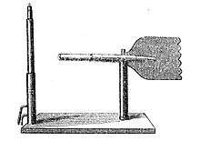


James Lind's anemometer of 1775 consisted of a glass U tube containing a liquid manometer (pressure gauge), with one end bent in a horizontal direction to face the wind and the other vertical end remains parallel to the wind flow. Though the Lind was not the first it was the most practical and best known anemometer of this type. If the wind blows into the mouth of a tube it causes an increase of pressure on one side of the manometer. The wind over the open end of a vertical tube causes little change in pressure on the other side of the manometer. The resulting elevation difference in the two legs of the U tube is an indication of the wind speed. However, an accurate measurement requires that the wind speed be directly into the open end of the tube; small departures from the true direction of the wind causes large variations in the reading.
The successful metal pressure tube anemometer of William Henry Dines in 1892 utilized the same pressure difference between the open mouth of a straight tube facing the wind and a ring of small holes in a vertical tube which is closed at the upper end. Both are mounted at the same height. The pressure differences on which the action depends are very small, and special means are required to register them. The recorder consists of a float in a sealed chamber partially filled with water. The pipe from the straight tube is connected to the top of the sealed chamber and the pipe from the small tubes is directed into the bottom inside the float. Since the pressure difference determines the vertical position of the float this is a measure of the wind speed.[7]
The great advantage of the tube anemometer lies in the fact that the exposed part can be mounted on a high pole, and requires no oiling or attention for years; and the registering part can be placed in any convenient position. Two connecting tubes are required. It might appear at first sight as though one connection would serve, but the differences in pressure on which these instruments depend are so minute, that the pressure of the air in the room where the recording part is placed has to be considered. Thus if the instrument depends on the pressure or suction effect alone, and this pressure or suction is measured against the air pressure in an ordinary room, in which the doors and windows are carefully closed and a newspaper is then burnt up the chimney, an effect may be produced equal to a wind of 10 mi/h (16 km/h); and the opening of a window in rough weather, or the opening of a door, may entirely alter the registration.
While the Dines anemometer had an error of only 1% at 10 mph (16 km/h) it did not respond very well to low winds due to the poor response of the flat plate vane required to turn the head into the wind. In 1918 an aerodynamic vane with eight times the torque of the flat plate overcame this problem.
Pitot tube static anemometers
Modern tube anemometers use the same principle as in the Dines anemometer but using a different design. The implementation uses a pitot-static tube which is a pitot tube with two ports, pitot and static, that is normally used in measuring the airspeed of aircraft. The pitot port measures the dynamic pressure of the open mouth of a tube with pointed head facing wind, and the static port measures the static pressure from small holes along the side on that tube. The pitot tube is connected to a tail so that it always makes the tube's head to face the wind. Additionally, the tube is heated to prevent rime ice formation on the tube.[8] There are two lines from the tube down to the devices to measure the difference in pressure of the two lines. The measurement devices can be manometers, pressure transducers, or analog chart recorders.[9]
Effect of density on measurements
In the tube anemometer the dynamic pressure is actually being measured, although the scale is usually graduated as a velocity scale. If the actual air density differs from the calibration value, due to differing temperature, elevation or barometric pressure, a correction is required to obtain the actual wind speed. Approximately 1.5% (1.6% above 6,000 feet) should be added to the velocity recorded by a tube anemometer for each 1000 ft (5% for each kilometer) above sea-level.
Effect of icing
At airports, it is essential to have accurate wind data under all conditions, including freezing precipitation. Anemometry is also required in monitoring and controlling the operation of wind turbines, which in cold environments are prone to in-cloud icing. Icing alters the aerodynamics of an anemometer and may entirely block it from operating. Therefore, anemometers used in these applications must be internally heated.[10] Both cup anemometers and sonic anemometers are presently available with heated versions.
Instrument location
In order for wind speeds to be comparable from location to location, the effect of the terrain needs to be considered, especially in regard to height. Other considerations are the presence of trees, and both natural canyons and artificial canyons (urban buildings). The standard anemometer height in open rural terrain is 10 meters.[11]
See also
- Air flow meter
- Anemoi, for the ancient origin of the name of this technology
- Anemoscope, ancient device for measuring or predicting wind direction or weather
- Automated airport weather station
- Particle image velocimetry
- Wind power forecasting
- Wind run
References
Citations
- ↑ "History of the Anemometer". Logic Energy. Retrieved 14 April 2013.
- ↑ World Meteorological Organization. "Vane anemometer". Eumetcal. Retrieved 6 April 2014.
- ↑ "Hot-wire Anemometer explanation". eFunda. Archived from the original on 10 October 2006. Retrieved 18 September 2006.
- ↑ Iten, Paul D. (29 June 1976). "Laser Doppler Anemometer". United States Patent and Trademark Office. Retrieved 18 September 2006.
- ↑ European Patent No. EPO 801311 A and USA Patent No. 5,877,416 (1999)
- ↑ "The Telltale project." Archived 20 February 2012 at the Wayback Machine.
- ↑ Dines, W. H. (1892). "Anemometer Comparisons". Quarterly Journal of the Royal Meteorological Society. Royal Meteorological Society (Great Britain), James Glaisher. 18: 168. Bibcode:1892QJRMS..18..165D. doi:10.1002/qj.4970188303. Retrieved 14 July 2014.
- ↑ "Instrumentation: Pitot Tube Static Anemometer, Part 1". Mt. Washington Observatory. Retrieved 14 July 2014.
- ↑ "Instrumentation: Pitot Tube Static Anemometer, Part 2". Mt. Washington Observatory. Retrieved 14 July 2014.
- ↑ Makkonen, L. et al. (2001) Anemometry in icing conditions. Journal of Atmospheric and Oceanic Technology 18:1457-1469
- ↑ Oke, Tim R. (2006). "3.5 Wind speed and direction". Initial Guidance to Obtain Representative Meteorological Observations At Urban Sites (PDF). Instruments and Observing Methods. 81. World Meteorological Organization. pp. 19–26. Retrieved 4 February 2013.
Bibliography
- "Anemometer", Encyclopædia Britannica, 9th ed., Vol. II, New York: Charles Scribner's Sons, 1878, pp. 24–26
- Dines, William Henry (1911), "Anemometer", Encyclopædia Britannica, 11th ed., Vol. II, Cambridge: Cambridge University Press, pp. 2–3.
- Meteorological Instruments, W.E. Knowles Middleton and Athelstan F. Spilhaus, Third Edition revised, University of Toronto Press, Toronto, 1953
- Invention of the Meteorological Instruments, W. E. Knowles Middleton, The Johns Hopkins Press, Baltimore, 1969
External links
| Wikimedia Commons has media related to Anemometer. |
| Look up anemometer in Wiktionary, the free dictionary. |
- Description of the development and the construction of an ultrasonic anemometer
- Robinson Cup Anemometer - Armagh Observatory
- Animation Showing Sonic Principle of Operation (Time of Flight Theory) - Gill Instruments
- Collection of historical anemometer
- Principle of Operation: Acoustic Resonance measurement - FT Technologies
- Thermopedia, "Anemometers (laser doppler)"
- Thermopedia, "Anemometers (pulsed thermal)"
- Thermopedia, "Anemometers (vane)"
- The Rotorvane Anemometer. Measuring both wind speed and direction using a tagged three-cup sensor