Three-phase AC railway electrification

Three-phase AC railway electrification was used in Italy, Switzerland and the United States in the early twentieth century. Italy was the major user, from 1901 until 1976, although lines through two tunnels also used the system; the Simplon Tunnel in Switzerland from 1906 to 1930, and the Cascade Tunnel of the Great Northern Railway in the United States from 1909 to 1939. The first line was in Switzerland, from Burgdorf to Thun (40 km or 25 mi), since 1899.[1] [2]
Advantages
The system provides regenerative braking with the power fed back to the system, so is particularly suitable for mountain railways (provided the grid or another locomotive on the line can accept the power). The locomotives use three-phase induction motors. Lacking brushes and commutators, they require less maintenance. The early Italian and Swiss systems used a low frequency (16⅔ Hz), and a relatively low voltage (3,000 or 3,600 volts) compared with later AC systems.
Disadvantages
The overhead wiring, generally having two separate overhead lines and the rail for the third phase, was more complicated, and the low-frequency used required a separate generation or conversion and distribution system. Train speed was restricted to one to four speeds, with two or four speeds obtained by pole-changing or cascade operation or both.
Historical Systems (no longer in use)
The following is a list of the railways that have used this method of electrification in the past:[3]
- The Cascade Tunnel of the Great Northern Railway.[4]
- The Giovi Railway between Genoa and Pontedecimo in Italy.[5]
- The Santa Fe - Gergal line in Spain.[3]
- The Simplon Tunnel in Switzerland.[6]
- The Valtellina Line of Italian State Railways.[7]
Current Systems (still in use)
The system is only used today for four rack (mountain) railways, where the overhead wiring is less complicated and restrictions on the speeds available less important. The four systems are as follows:
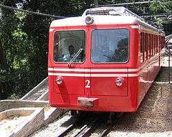
- The Corcovado Rack Railway in Rio de Janeiro Brazil.
- The Gornergratbahn in Switzerland.
- The Jungfraubahn in Switzerland.
- The Petit train de la Rhune in France, still using the original locomotives of 1912
They are nowadays industrial rather than low frequency (50 Hz, or 60 Hz (Brazil)), using between 725 and 3,000 volts.
Converter systems
This category does not cover railways with a single-phase (or DC) supply which is converted to three-phase on the locomotive or power car, e.g. most railway equipment from the 1990s and earlier using solid-state converters. The Kando system of the 1930s developed by Kálmán Kandó and used in Hungary and Italy used rotating converters on the locomotive to convert the single-phase supply to three phases, as did the Phase-splitting system on the Norfolk and Western Railroad in the USA.
Locomotives

Usually the locomotives had one, two or four motors on the body chassis (not on the bogies), and did not require gearing. The induction motors are designed to run at a particular synchronous speed, and when they run above the synchronous speed downhill, power is fed back to the system. Pole changing and cascade (concatenation) working was used to allow two or four different speeds, and resistances (often liquid rheostats) were required for starting. In Italy freight locomotives used plain cascade with two speeds, 25 and 50 km/h (16 and 31 mph); while express locomotives used cascade combined with pole-changing giving four speeds, 37, 50, 75 and 100 km/h (23, 31, 46 and 62 mph).[2] With the use of 3,000 or 3,600 volts at 16⅔ (16.7) Hz, the supply could be fed directly to the motor without an onboard transformer.
Generally the motor(s) fed a single axle with other wheels linked by connecting rods, as the induction motor is sensitive to speed variations and with non-linked motors on several axles the motors on worn wheels would do little or even no work as they would rotate faster.[8] This motor characteristic led to a mishap in the Cascade Tunnel to a GN east-bound freight train with four electric locos, two on the head and two pushing. The two pushers suddenly lost power and the train gradually slowed to a stop. But the lead unit engineer was unaware that his train had stopped, and held the controller on the power position until the usual time to transit the tunnel had elapsed. Not seeing daylight, he finally shut down the locomotive, and found that the wheels of his stationary loco had ground through two-thirds of the rail web.[9]

Overhead wiring
Generally two separate overhead wires are used, with the rail for the third phase, though occasionally three overhead wires are used. At junctions, crossovers and crossings the two lines must be kept apart, with a continuous supply to the locomotive, which must have two live conductors wherever it stops. Hence two collectors per overhead phase are used, but the possibility of bridging a dead section and causing a short circuit from the front collector of one phase to the back collector of the other phase must be avoided.[10] The resistance of the rails used for the third phase or return is higher for AC than for DC because of the "skin" effect, but lower for the low frequency used than for industrial frequency. Losses are also increased, though not in the same proportion, as the impedance is largely reactive.[11]
The locomotive needs to pick up power from two (or three) overhead conductors. Early locomotives on the Italian State Railways used a wide bow collector which covered both wires but later locomotives used two pantographs side by side. In the United States, a pair of trolley poles were used. They worked well with a maximum speed of 15 miles per hour (24 km/h). The dual conductor pantograph system is used on four mountain railways that continue to use three-phase power (Corcovado Rack Railway in Rio de Janeiro, Brazil, Jungfraubahn and Gornergratbahn in Switzerland and the Petit train de la Rhune in France).
See also
- Three-phase electric power
- Railway electrification system#Polyphase alternating current systems
- Category:Three-phase AC locomotives
Footnotes
- ↑ Middleton (1974), p. 156.
- 1 2 Meares & Neale (1933), p. 630-631, para 919
- 1 2 Burch (1923), p. 133.
- ↑ Burch (1923), p. 349.
- ↑ Burch (1923), p. 342.
- ↑ Burch (1923), p. 346.
- ↑ Burch (1923), p. 339.
- ↑ Starr (1953), p. 347.
- ↑ Middleton (1974), p. 161.
- ↑ Maccall (1930), p. 412.
- ↑ Maccall (1930), p. 423-424.
References
- Burch, Edward Parris (1911). Electric Traction for Railway Trains. New York: McGraw-Hill.
- Cornolò, Giovanni; Gut, Martin (2000). Albertelli, Ermanno, ed. Ferrovie trifasi nel mondo, 1895-2000 [Three-phase railways in the World] (in Italian). Parma. ISBN 978-8887372106.
- Kalla-Bishop, P.M. (1971). Italian Railways (Railway Histories of the World). England: David and Charles. ISBN 978-0715351680. p. 98
- Maccall, William Tolmé (1930) [1923]. Alternating Current: Electrical Engineering (2nd ed.). Cambridge: University Tutorial Press. pp 412–3 & 423-5
- Meares, J.W.; Neale, R.E. (1933). Electrical Engineering Practice. Volume III. London: Chapman and Hall. ASIN B00N997B1K. pp 542–3 (para 872) & pp 630–1 (para 919)
- Middleton, William D. (1974). When the Steam Railroads Electrified. Milwaukee: Kalmbach Publishing Co. ISBN 0-89024-028-0.
- Middleton, William D. (March 2002). When the Steam Railroads Electrified (2nd ed.). Bloomington, Indiana: Indiana University Press. ISBN 978-0-253-33979-9.
- Starr, Arthur Tisso (1953) [1937]. Generation, Transmission and Utilization of Electrical Power (3rd ed.). London: Pitman. OCLC 11069538. p 347