Telescopic sight
A telescopic sight, commonly called a scope, is a sighting device that is based on an optical refracting telescope. They are equipped with some form of graphic image pattern (a reticle) mounted in an optically appropriate position in their optical system to give an accurate aiming point. Telescopic sights are used with all types of systems that require accurate aiming but are most commonly found on firearms, particularly rifles. Other types of sights are iron sights, reflector (reflex) sights, and laser sights. The optical components may be combined with optoelectronics to form a night scope.
History
The first experiments directed to give shooters optical aiming aids go back to the early 17th century. For centuries different optical aiming aids and primitive predecessors of telescopic sights were created that had practical or performance limitations.
The first documented telescopic rifle sight was invented between 1835 and 1840. In a book titled The Improved American Rifle, written in 1844, civil engineer John R. Chapman documented the first telescopic sights made by Morgan James of Utica, NY. Chapman gave James the concepts and some of the design, whereupon they produced the Chapman-James sight. In 1855, William Malcolm of Syracuse, NY began producing his own sight. Malcolm used an original design incorporating achromatic lenses like those used in telescopes, and improved the windage and elevation adjustments. They were between three and twenty magnification (possibly more). Malcolm's and those made by L. M. Amidon of Vermont were the standard during the Civil War.[1][2]
Still other telescopic rifle sights of the same period were the Davidson and the Parker Hale.[3][4]

An early practical refractor telescope based telescopic sight was built in 1880 by August Fiedler (Stronsdorf, Austria), forestry commissioner of Prince Reuss.[5] Later telescopic sights with extra long eye relief became available for handgun and scout rifle use. A historic example of a telescopic sight with a long eye relief is the German ZF41 which was used during World War II on Karabiner 98k rifles.
An early example of a man portable telescopic sight for low visibility/night use is the Zielgerät (aiming device) 1229 (ZG 1229), also known by its code name Vampir. The ZG 1229 Vampir was a Generation 0 active infrared night vision device developed for the Wehrmacht for the StG 44 assault rifle, intended primarily for night use. The issuing of the ZG 1229 Vampir system to the military started in 1944 and it was used on a small scale in combat from February 1945 until the final stages of World War II.
Types

Telescopic sights are classified in terms of the optical magnification and the objective lens diameter, e.g. 10×50. This would denote 10 times magnification with a 50 mm objective lens. In general terms, larger objective lens diameters, due to their ability to gather larger amounts of light, provide a larger exit pupil and hence provide a brighter image at the eyepiece. On fixed magnification sights the magnification power and objective diameter should be chosen on the basis of the intended use.
There are also telescopic sights with variable magnification. The magnification can be varied by manually operating a zoom mechanism. Variable sights offer more flexibility regarding shooting at varying ranges, targets and light conditions and offer a relative wide field of view at lower magnification settings. The syntax for variable sights is the following: minimal magnification – maximum magnification × objective lens, for example, 3–9×40.
Confusingly, some older telescopic sights, mainly of German or other European manufacture, have a different classification where the second part of the designation refers to 'light gathering power.' In these cases, a 4×81 (4× magnification) sight would be presumed to have a brighter sight picture than a 2.5×70 (2.5× magnification), but the objective lens diameter would not bear any direct relation to picture brightness, as brightness is affected also by the magnification factor. Typically objective lenses on early sights are smaller than modern sights, in these examples the 4×81 would have an objective approximately 36mm diameter and the 2.5×70 should be approximately 21mm (relative luminosity is the square of the exit pupil as measured in mm; a 36mm objective lens diameter divided by the 4x magnification gives an exit pupil of 9mm; 9x9=81)
Optical parameters
Telescopic sights are usually designed for the specific application for which they are intended. Those different designs create certain optical parameters. Those parameters are:
Magnification — The ratio of the focal length of the eyepiece divided into the focal length of the objective gives the linear magnifying power of telescopes. A magnification of factor 10, for example, produces an image as if one were 10 times closer to the object. The amount of magnification depends upon the application the telescopic sight is designed for. Lower magnifications lead to less susceptibility to shaking. A larger magnification leads to a smaller field of view.
Objective lens diameter – The diameter of the objective lens determines how much light can be gathered to form an image. It is usually expressed in millimeters.
Field of view — The field of view of a telescopic sight is determined by its optical design. It is usually notated in a linear value, such as how many meters (feet) in width will be seen at 100 m (110 yd), or in an angular value of how many degrees can be viewed.
Exit pupil — Telescopic sights concentrate the light gathered by the objective into a beam, the exit pupil, whose diameter is the objective diameter divided by the magnifying power. For maximum effective light-gathering and brightest image, the exit pupil should equal the diameter of the fully dilated iris of the human eye — about 7 mm, reducing with age. If the cone of light streaming out of the eyepiece is larger than the pupil it is going into, any light larger than the pupil is wasted in terms of providing information to the eye.
However, a larger exit pupil makes it easier to put the eye where it can receive the light: anywhere in the large exit pupil cone of light will do. This ease of placement helps avoid vignetting, which is a darkened or obscured view that occurs when the light path is partially blocked. And, it means that the image can be quickly found which is important when aiming at game animals that move rapidly. A narrow exit pupil telescopic sight may also be fatiguing because the instrument must be held exactly in place in front of the eyes to provide a useful image. Finally, many people in Europe use their telescopic sights at dusk, dawn and at night, when their pupils are larger. Thus the daytime exit pupil of about 3 to 4 mm is not a universally desirable standard. For comfort, ease of use, and flexibility in applications, larger telescopic sights with larger exit pupils are satisfying choices even if their capability is not fully used by day.
Eye relief — Eye relief is the distance from the rear eyepiece lens to the exit pupil or eye point.[6] It is the distance the observer must position his or her eye behind the eyepiece in order to see an unvignetted image. The longer the focal length of the eyepiece, the greater the eye relief. Typical telescopic sights may have eye relief ranging from 25 mm (0.98 in) to over 100 mm (3.9 in), but telescopic sights intended for scout rifles or handguns need much longer eye relief to present an unvignetted image. Telescopic sights with relatively long eye relief are favourable to avoid recoil induced facial and eye injuries and use in instances where it is difficult to hold the eyepiece steady. Eye relief can be particularly important for eyeglass wearers. The eye of an eyeglass wearer is typically further from the eye piece which necessitates a longer eye relief in order to still see the entire field of view.
Reticles


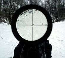
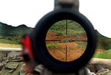
Telescopic sights come with a variety of different reticles, ranging from the traditional crosshairs to complex reticles designed to allow the shooter to estimate accurately the range to a target, to compensate for the bullet drop, and to compensate for the windage required due to crosswinds. A user can estimate the range to objects of known size, the size of objects at known distances, and even roughly compensate for both bullet drop and wind drifts at known ranges with a reticle-equipped scope.
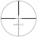
For example, with a typical Leupold brand duplex 16 Minute of Angle (MOA) reticle (of a type as shown in image B) on a fixed power scope, the distance from post to post (that is, between the heavy lines of the reticle spanning the center of the scope picture) is approximately 32 inches (81 centimetres) at 200 yards (180 m), or, equivalently, approximately 16 inches (41 centimetres) from the center to any post at 200 yards. If a target of a known diameter of 16 inches fills just half of the total post-to-post distance (i.e. filling from scope center to post), then the distance to target is approximately 200 yards (180 m). With a target of a diameter of 16 inches that fills the entire sight picture from post to post, the range is approximately 100 yards. Other ranges can be similarly estimated accurately in an analog fashion for known target sizes through proportionality calculations. Holdover, for estimating vertical point of aim offset required for bullet drop compensation on level terrain, and horizontal windage offset (for estimating side to side point of aim offsets required for wind effect corrections) can similarly be compensated for through using approximations based on the wind speed (from observing flags or other objects) by a trained user through using the reticle marks. The less-commonly used holdunder, used for shooting on sloping terrain, can even be estimated by an appropriately-skilled user with a reticle-equipped scope, once both the slope of the terrain and the slant range to target are known.
There are two main types of reticles:
- Wire reticles
- Etched reticles
Wire reticles are the oldest type of reticles and are made out of metal wire or thread. They are mounted in an optically appropriate position in the telescopic sight's tube. Etched reticles are images of the desired reticle layout that are etched on an optic element. This optical element (lens) with the etched reticle is then mounted in the telescopic sights tube as an integrated part of the optics chain of the sight. When backlit through the ocular, a wire reticle will reflect incoming light and not present a fully opaque (black) reticle with high contrast. An etched reticle will stay fully opaque (black) if backlit. Etched reticles are considered by most to be a more refined solution and offer greater reticle layout flexibility. Because of this, some manufacturers can provide client-designed custom reticles on special order. In the more expensive and high-end contemporary telescopic sights, etched reticles dominate the market. In cheaper telescopic sights, wire reticles are still often mounted to avoid a rather specialized and costly production step.
Mil-dot reticles


Many modern reticles are designed for (stadiametric) rangefinding purposes. Perhaps the most popular and well-known ranging reticle is the "Mil-dot" reticle, which consists of duplex crosshairs with small dots at milliradian (Mil or 1/1000 of a radian) intervals in the field of view.[7] This reticle has gained significant acceptance in NATO and other military and law enforcement organizations. Training and practice will enable a user to measure the range to objects of known size, the size of objects at known distances, and compensate for both bullet drop and wind drift at known ranges with reasonable accuracy. To promote methodological uniformity, (mental) calculations and communication between spotters and snipers in sniper teams, the elevation or vertical adjustment and windage controls of Mil-dot reticle equipped telescopic sights are usually adjustable in (decimal) 0.1 milliradian increments. There are, however, (military) Mil-dot equipped telescopic sights that use coarser or finer reticle adjustment increments.
By means of a mathematical formula – (width or height of the target/ number of mil of dots) x 1000 = distance – the user can measure the range to a target. An object of 1 meter tall or wide is exactly 1 Mil tall or wide at 1000 meters distance. If the user sees an object of 1.8 m tall for example as three mil dots tall through the riflescope the object is at 600 m distance – (1.8 / 3) x 1000 = 600.
Reticle focal plane
Telescopic sights based on refracting telescopes using image erector lenses to present the user with an upright image have two planes of focus where a reticle can be placed: at the focal plane between the objective and the image erector lens system (the First Focal Plane (FFP)), or the focal plane between the image erector lens system and the eyepiece (the Second Focal Plane (SFP)).[8] On fixed power telescopic sights there is no significant difference, but on variable power telescopic sights a first focal plane reticle expands and shrinks along with the rest of the image as the magnification is adjusted, while a second focal plane reticle would appear the same size and shape to the user as the target image grows and shrinks. In general, the majority of modern variable-power scopes are SFP unless stated otherwise. Every European high-end telescopic sight manufacturer offers FFP reticles on variable power telescopic sights, since the optical needs of European hunters who live in jurisdictions that allow hunting at dusk, night and dawn differ from hunters who traditionally or by legislation do not hunt in low light conditions.
The main disadvantage of SFP designs comes with the use of range-finding reticles such as mil-dot. Since the proportion between the reticle and the target is dependent on selected magnification, such reticles only work properly at one magnification level, typically the highest power. Some long-range shooters and military snipers use fixed-power scopes to eliminate this potential for error. Some SFP scopes take advantage of this aspect by having the shooter adjust magnification until the target fits a certain way inside the reticle and then extrapolate the range based on the power adjustment. Some Leupold hunting scopes with duplex reticles allow range estimation to a Whitetail Buck deer by adjusting magnification until the area between the backbone and the brisket fits between the crosshairs and the top thick post of the reticle. Once that's done, the range be read from the scale printed on the magnification adjustment ring.
Although FFP designs are not susceptible to magnification-induced errors, they have their own disadvantages. It's challenging to design a reticle that is visible through the entire range of magnification: a reticle that looks fine and crisp at 24x magnification may be very difficult to see at 6x . On the other hand, a reticle that's easy to see at 6x may be thick enough at 24x to make precision shots difficult. Shooting in low light conditions also tends to require either illumination or a bold reticle, along with lower magnification to maximize light gathering. In practice, these issues tend to significantly reduce the available magnification range on FFP scopes compared to SFP, and FFP scopes are much more expensive compared to SFP models of similar quality. Most high-end optics manufacturers leave the choice between a FFP or SFP mounted reticle to the customer or have scope product models with both setups.
Variable power telescopic sights with FFP reticles have no problems with point of impact shifts. Variable power telescopic sights with SFP reticles can have slight point-of-impact shifts through their magnification range, caused by the positioning of the reticle in the mechanical zoom mechanism in the rear part of the telescopic sight. Normally these impact shifts are insignificant, but accuracy-oriented users, who wish to use their telescopic sight trouble-free at several magnification levels, often opt for FFP reticles. Around the year 2005 Zeiss[9] was the first high-end European telescopic sight manufacturer who brought out variable magnification military grade telescopic sight models with rear SFP mounted reticles. They get around impermissible impact shifts by laboriously hand-adjusting every military grade telescopic sight. The American high-end telescopic sight manufacturer U.S. Optics Inc.[10] also offers variable magnification military grade telescopic sight models with SFP mounted reticles.
Reticle illumination
Either type of reticle can be illuminated for use in low-light or daytime conditions. With any illuminated low-light reticle, it is essential that its brightness can be adjusted. A reticle that is too bright will cause glare in the operator's eye, interfering with his ability to see in low-light conditions. This is because the pupil of the human eye closes quickly upon receiving any source of light. Most illuminated reticles provide adjustable brightness settings to adjust the reticle precisely to the ambient light.
Illumination is usually provided by a battery powered LED, though other electric light sources can be used. The light is projected forward through the scope, and reflects off the back surface of the reticle. Red is the most common colour used, as it least impedes the shooter's natural night vision. This illumination method can be used to provide both daytime and low-light conditions reticle illumination.
Radioactive isotopes can also be used as a light source, to provide an illuminated reticle for low-light condition aiming. In sights like the SUSAT or Elcan C79 Optical Sight tritium-illuminated reticles are used for low-light condition aiming. Trijicon Corporation uses tritium in their combat and hunting-grade firearm optics, including the ACOG. The (radioactive) tritium light source has to be replaced every 8–12 years, since it gradually loses its brightness due to radioactive decay.
With fiber optics ambient (day)light can be collected and directed to an illuminated daytime reticle. Fiber-optics reticles automatically interact with the ambient light level that dictates the brightness of the reticle. Trijicon uses fiber optics combined with other low-light conditions illumination methods in their AccuPoint telescopic sights and some of their ACOG sights models.
Parallax compensation
Parallax problems result from the image from the objective not being coincident with the reticle. If the image is not coplanar with the reticle (that is the image of the objective is either in front of or behind the reticle), then putting the eye at different points behind the ocular causes the reticle crosshairs to appear to be at different points on the target. This optical effect causes parallax induced aiming errors that can make a telescopic sight user miss a small target at a distance for which the telescopic sight was not parallax adjusted.
To eliminate parallax induced aiming errors, telescopic sights can be equipped with a parallax compensation mechanism which basically consists of a movable optical element that enables the optical system to project the picture of objects at varying distances and the reticle crosshairs pictures together in exactly the same optical plane. There are two main methods to achieve this.
- By making the objective lens of the telescopic sight adjustable so the telescopic sight can compensate parallax errors. These models are often called AO or A/O models, for adjustable objective.
- By making an internal lens in the internal optical groups mounted somewhere in front of the reticle plane adjustable so the telescopic sight can compensate parallax errors. This method is technically more complicated to build, but generally more liked by parallax adjustable telescopic sight users—unlike AO models, which are read from the top, the sidewheel's setting can be read with minimal movement of the head. These models are often called side focus or sidewheel models.[11]
Most telescopic sights lack parallax compensation because they can perform very acceptably without this refinement. Telescopic sights manufacturers adjust these scopes at a distance that best suits their intended usage. Typical standard factory parallax adjustment distances for hunting telescopic sights are 100 yd or 100 m to make them suited for hunting shots that rarely exceed 300 yd/m. Some long range target and military style telescopic sights without parallax compensation may be adjusted to be parallax free at ranges up to 300 yd/m to make them better suited for aiming at 300 yd/m+ ranges. Scopes for rimfire guns, shotguns, and muzzleloaders that are rarely fired at 100 yd/m+ ranges will have shorter parallax settings, commonly 50 yd/m for rimfire scopes and 100 yd/m for shotguns and muzzleloaders. Scopes for airguns that are commonly used at short ranges are very often found with adjustable parallax, usually in the form of an adjustable objective, or AO. These may adjust down as far as 3 yards (2.7 m).
The reason why scopes intended for short range use are often equipped with parallax compensation is that at short range (and at high magnification) parallax errors become more noticeable. A typical scope objective has a focal length of 100 mm. An optical ideal 10× scope in this example has been perfectly parallax corrected at 1000 m and functions flawlessly at that distance. If the same scope is used at 100 m the target-picture would be projected (1000 m / 100 m) / 100 mm = 0.1 mm behind the reticle plane. At 10× magnification the error would be 10 × 0.1 mm = 1 mm at the ocular. If the same scope was used at 10 m the target-picture would be (1000 m / 10 m) / 100 mm = 1 mm projected behind the reticle plane. When magnified ten times the error would be 10 mm at the ocular.
Bullet Drop Compensation
Bullet Drop Compensation (BDC) (sometimes referred to as ballistic elevation) is a feature available on some rifle scopes. The feature compensates for the effect of gravity on the bullet at given distances (referred to as "bullet drop") in flat fire scenarios. The feature must be tuned for the particular ballistic trajectory of a particular combination of gun and cartridge at a predefined muzzle velocity and air density. Telescopic sights designed for military use like the ACOG or PSO-1 featuring BDC reticles or elevation turrets with range markings are fairly common, though commercial manufacturers offer the option to install a BDC reticle or elevation turret as long as the customer supplies the necessary ballistic data.[12] Since the usage of standardized ammunition is an important prerequisite to match the BDC feature to the external ballistic behaviour of the employed projectiles, telescopic sights with BDC are generally intended to assist with field shooting at targets at varying medium to longer ranges rather than precise long range shots. With increasing range inevitable BDC induced errors will occur when the environmental and meteorological circumstances deviate from the predefined circumstances for which the BDC was calibrated. Marksmen can be trained to understand the main forces acting on the projectile and their effect on their particular gun and ammunition and the effects of external factors at longer ranges to counter these errors.
Adjustment controls

A telescopic sight can have several adjustment controls.
- Focusing control at the ocular end of the sight – meant to obtain a sharp picture of the object and reticle.
- Elevation or vertical adjustment control of the reticle.
- Zero-stop elevation controls can be set to prevent inadvertently dialing the adjustment knob "below" the primary zero (usually 100 meters or 100 yards for long-range scopes), or at least prevent dialing more than a couple adjustment clicks below zero. This feature is also useful on long-range scopes because it allows the shooter to physically verify the elevation knob is dialed all the way down avoiding confusion regarding the elevation status on two- or multi-revolution elevation knobs.
- Windage or horizontal adjustment control of the reticle.
- Magnification control – meant to change the magnification by turning a ring that is generally marked with several magnification power levels.
- Illumination adjustment control of the reticule – meant to regulate the brightness level of the lit parts of the reticles crosshairs.
- Parallax compensation control.
Most contemporary telescopic sights offer the first three adjustment controls. The other three are found on telescopic sights that offer a variable magnification, an illuminated reticle and/or parallax compensation. A rather common problem with the elevation and windage adjustment controls is that once smooth working adjustment turrets 'get stuck' over the years. This is generally caused by long term lack of movement in the lubricated turret mechanisms.
Older telescopic sights often did not offer windage and elevation adjustments in the scope, but rather used adjustable mounts to provide adjustment. Some modern mounts also allow for adjustment, but it is generally intended to supplement the scope adjustments. For example, some situations require fairly extreme elevation adjustments, such as very short range shooting common with airguns, or very long range shooting, where the bullet drop becomes very significant. Also, loose manufacturing tolerances may result in base mounting holes being less than perfectly aligned with the bore. In this case, rather than adjusting the scope to the extremes of its elevation adjustment, the scope mount can be adjusted. This allows the scope to operate near the center of its adjustment range, which puts less stress on the internals. Some companies offer adjustable bases, while others offer tapered bases with a given amount of elevation built in (commonly listed in MOA). The adjustable bases are more flexible, but the fixed bases are far more durable, as adjustable bases may loosen and shift under recoil.[13][14] Also, adjustable bases are considerably more expensive, as well.
Accessories
Typical accessories for telescopic sights are:
- Lens hoods for mounting on the objective and/or ocular to reduce/eliminate image quality impairing stray light and at the ocular secondary to avoid recoil induced facial and eye injuries.
- Lens hoods that extend the full length of a gun barrel to improve image quality by blocking out shot strings induced mirage ("heat waves" or aberrations resulting from a hot gun barrel).
- Covers to protect the objective and/or ocular external lens surface against foul weather and damage. There are slide-over, bikini and flip-open type covers without or with transparent covering material.
- Optical filters like Grey, Yellow and Polarising filters to optimize image quality in various lighting conditions.
- Kill Flash or honeycomb filters to eliminate light reflections from the objective that could compromise a sniper.
- Eye-safe laser filters to protect operators against being wounded/blinded by laser light sources. These filters are often an internal part in the assembly of lens elements.
- Transit and protection pouches and cases.
Optronic technologies
Integrated laser rangefinder
In 1997 Swarovski Optik introduced the LRS series telescopic sight, the first riflescope on the civilian market with an integrated laser rangefinder.[15] The LRS 2-12x50 sight can measure ranges up to 600 m (660 yd).[16] The LRS sights are currently (2008) not produced anymore, but sights with similar features are commercially available from several manufacturers.
Ballistic support devices
An integrated ballistic computer/riflescope system known as BORS has been developed by the Barrett Firearms Company and became commercially available around 2007. The BORS module is in essence an electronic Bullet Drop Compensation (BDC) sensor/calculator package intended for long-range sniping out to 2,500 m (2,700 yd) for some telescopic sight models made by Leupold and Nightforce. To establish the appropriate elevation setting the shooter needs to enter the ammunition type into the BORS (using touch pads on the BORS console) determine the range (either mechanically or through a laser rangefinder) and crank the elevation knob on the scope until the proper range appears in the BORS display. The BORS automatically determines the air density, as well as the cant or tilt in the rifle itself, and incorporates these environmental factors into its elevation calculations.[17]
The SAM (Shooter-supporting Attachment Module) measures and provides aiming and ballistic relevant data and displays this to the user in the ocular of the Zeiss 6-24x72 telescopic sight it is developed for.[18] The SAM has different sensors integrated (temperature, air pressure, shooting angle) and calculates the actual ballistic compensation. All indications are displayed in the ocular. It memorizes up to 4 different ballistics and 4 different firing tables. So it is possible to use 1 SAM with 4 total different loads or weapons without an additional adjustment.
CCD and LCD technology
A totally different approach has been applied in the ELCAN DigitalHunter Digital Rifle Scope series which combines CCD and LCD technology with electronic ballistics compensation, automatic video capture, 4 field selectable reticles and customizable reticles. In 2008 a DigitalHunter DayNight Riflescope that uses infrared light captured by the CCD to enhance low light capabilities became available. It is also possible to attach infrared light sources to use this telescopic sight as an active night sight in total darkness, though the image quality, and overall performance is poor. Some jurisdictions however forbid or limit to use of night vision devices for civilian or gun aiming use.
Mounting

As very few firearms come with built-in telescopic sights (military designs such as the Steyr AUG, SAR 21 and the H&K G36 being exceptions) mounting a scope to a firearm requires additional equipment. Equipment is available to mount scopes on most production firearms. A typical scope mounting system consists of two parts, the scope base and the scope rings. By picking the appropriate combination of scope base to fit the firearm and scope rings to fit the scope, a wide range of scopes may be mounted to most firearms. With the appropriate combination of adjustable scope bases and scope rings it is also possible to mount several telescopic sights on the same gun to make the gun more versatile. However, it is important to take into consideration whether or not a gun is particularly hard to mount. If it is or if a gun is intended for long-range shooting, it could be that the amount of vertical adjustment range is smaller than required. This can be solved with the help of a vertically canted base or canted rings. Typical cant angles offered by mounting components manufacturers are 20 and 30 MOA.
Scope bases
The base is attached to the rifle, usually with screws, and is often designed to have a low profile, and to allow use of the iron sights if the scope is not present. Some manufacturers provide integral bases on many of their firearms; an example of such a firearm is the Ruger Super Redhawk revolver. The most commonly encountered mounting systems are the 3/8 inch (9.5 mm) and the 11 mm dovetail mounts (sometimes called tip-off mounts), commonly found on rimfires and air guns, the Weaver type base and the STANAG 2324 (MIL-STD-1913 "Picatinny rail") base. Ruger uses a proprietary scope base system, though adapters are available to convert the Ruger bases into Weaver type bases. Scope base and mounting systems are also manufactured in Europe. Specialized manufacturers like Ernst Apel GmbH[19][20] offer an elaborate program of mounting solutions for many different guns. Some of the European mounting solutions are virtually unknown and hence rarely applied in America. Many European gun manufacturers also developed and offer proprietary scope base systems for their guns, for example Sako has tapered dovetails and Tikka uses 16mm dovetail.
Scope rings
In addition to needing the right type of connector to attach to the desired base, scope rings must be used to hold the scope to the mount. The rings must be of the proper size to fit the scope; common sizes are 3/4 inch (19.05 mm), 22 mm, 1 inch (25.4 mm), 26 mm, 30 mm and 34 mm. Red dot sights commonly are found in larger sizes, such as 40 mm, and these often use ringless mounting systems designed to fit dovetail or Weaver type bases. Rings are also available in a variety of heights and materials. Ring height is chosen to place the scope high enough to clear the firearm, and at a height comfortable for the shooter.
Scope mounting rails
European telescopic sight manufacturers often offer the option to have mounting rails underneath the riflescope to provide for mounting solutions that do not use scope rings or a single scope ring around the objective of the scope. These rails are an integral part of the scope body and can not be removed. The mounting rail permits the riflescope to be securely and tension-free mounted at the preferred height and correct distance from the shooter's eye and on different guns.
There are several mounting rail systems offered:
- Standard prism
- Zeiss ZM/VM, also used by DOCTER
- Swarovski Optik SR
- Schmidt & Bender Convex
The traditional standard prism mounting rail system requires to have the scope rail drilled from the side for fixture screws. The more recent propriety systems mainly offer aesthetic advantages for people who have problems with redundant drill holes in sight in case the riflescope is used on different guns. To avoid drilling the scope rail, the propriety rail mounting systems have special shape connections machined in the inside of the rail. These shape connections prevent ever showing any exterior damage from mounting work on the rifle scope. The propriety rail systems use matching slide-in mount fasteners to connect the riflescope to the gun. Some propriety rails also offer the possibility to tilt the scope up to 1° to the left or right.
Rail interface systems

For mounting telescopic sights and/or other accessories to guns several rail interface systems are available to provide a standardized mounting platform. Probably the best known rail interface system is the Picatinny rail or STANAG 2324 rail or MIL-STD-1913 rail used by NATO forces and other official and civil users. The name of this interface system, which dates back to 3 February 1995, comes from the Picatinny Arsenal in New Jersey, where it was originally tested and was used to distinguish it from other rail standards at the time. The Picatinny rail comprises a series of ridges with a T-shaped cross-section interspersed with flat "spacing slots". Telescopic sight mounting rings are mounted either by sliding them on from one end or the other; by means of a "rail-grabber" which is clamped to the rail with bolts, thumbscrews or levers; or onto the slots between the raised sections.
Another commercially available rail interface system is the Weaver rail mount from Weaver Optics. The only difference between the Picatinny rail and the Weaver rail is the size and spacing of the slots, although almost all rail-grabber-mounted accessories are manufactured such that they can mounted on either type of rail.
The NATO Accessory Rail (or NAR), defined by the new modernization agreement STANAG 4694 approved by NATO on 8 May 2009, is a new rail interface system standard for mounting auxiliary equipment such as telescopic sights, tactical lights, laser aiming modules, night vision devices, reflex sights, foregrips, bipods, and bayonets to small arms such as rifles and pistols.[21] The NATO Accessory Rail is backwards-compatible with the STANAG 2324 or MIL-STD 1913 Picatinny rail.
Mounting issues
Scopes for use on light-recoiling firearms, such as rimfire guns, can be mounted with a single ring, and this method is not uncommon on handguns, where space is at a premium. Most scopes are mounted with two rings, one in the front half of the scope and one on the back half, which provides additional strength and support. The heaviest-recoiling firearms, such as Thompson Center Arms Contender pistols in heavy-recoiling calibers, will use three rings for maximum support of the scope. Use of too few rings can result not only in the scope moving under recoil, but also excessive torque on the scope tube as the gun rolls up under recoil.
Scopes on heavy-recoiling firearms and spring piston airguns (which have a heavy "reverse recoil" caused by the piston reaching the end of its travel) suffer from a condition called scope creep, where the inertia of the scope holds it still as the firearm recoils under it. Because of this, scope rings must be precisely fitted to the scope, and tightened very consistently to provide maximum hold without putting uneven stress on the body of the scope. Rings that are out of round, misaligned in the bases, or tightened unevenly can warp or crush the body of the scope.[22]
Another problem is mounting a scope on a rifle where the shell is ejected out the top of the action, such as some lever action designs. Usually this results in the scope being offset to one side (to the left for right-handed people, right for left-handed) to allow the shell to clear the scope. Alternately a scout rifle type mount can be used, which places a long-eye-relief scope forward of the action.
A firearm may not always be able to fit all aiming optics solutions, so it is wise to have a preferred aiming optics solution first reviewed by a professional.
Uses
Telescopic sights have both advantages and disadvantages relative to iron sights. Standard doctrine with iron sights is to focus the eye on the front sight and align it with the resulting blur of the target and the rear sight; most shooters have difficulty doing this, as the eye tends to be drawn to the target, blurring both sights. Gun users over 30 years of age with keen eyesight will find it harder to keep the target, front sight element and rear sight element in focus well enough for aiming purposes, as human eyes gradually lose focusing flexibility with rising age, due to presbyopia. Telescopic sights allow the user to focus on both the crosshair and the target at the same time, as the lenses project the crosshair into the distance (50 m or yd for rimfire scopes, 100 m or yd more for centerfire calibers). This, combined with telescopic magnification, clarifies the target and makes it stand out against the background. The main disadvantage of magnification is that the area to either side of the target is obscured by the tube of the sight. The higher the magnification, the narrower the field of view in the sight, and the more area is hidden. Rapid fire target shooters use reflex sights, which have no magnification; this gives them the best field of view while maintaining the single focal plane of a telescopic sight. Telescopic sights are expensive and require additional training to align. Sight alignment with telescopic sights is a matter of making the field of vision circular to minimize parallax error. For maximum effective light-gathering and brightest image, the exit pupil should equal the diameter of the fully dilated iris of the human eye — about 7 mm, reducing with age.
Military


Though they had been used as early as the 1850s on rifles, and even earlier for other tasks, until the 1980s, when optical device and assault rifle combinations such as the Austrian Steyr AUG and the British SUSAT mounted on the SA80, became standard issue, military use of telescopic sights was restricted to snipers because of the fragility and expense of optical components. Additionally the glass lenses are prone to breakage, and environmental conditions such as condensation, precipitation, dirt, and mud obscure external lenses. The scope tube also adds significant bulk to the rifle. Snipers generally used moderate to high magnification scopes with special reticles that allow them to estimate range to the target. Since the 1990s many other armed forces have adopted optical devices for general issue to infantry units and the rate of adoption has increased as the cost of manufacture has fallen.
Telescopic sights provide some tactical disadvantages. Snipers rely on stealth and concealment to get close to their target. A telescopic sight can hinder this because sunlight may reflect from the lens and a sniper raising his head to use a telescopic sight might reveal his position. The famous Finnish sniper Simo Häyhä preferred to use iron sights rather than telescopic sights to present less of a target. Harsh climate can also cause problems for telescopic sights as they are less rugged than iron sights. Many Finnish snipers in WWII used iron sights heavily because telescopic sights did not cope with very cold Finnish winters.
The market for military telescopic sights intended for military long-range shooting is highly competitive. Several high end optics manufacturers are constantly adapting and improving their telescopic sights to fulfill specific demands of military organizations. Two European companies that are active this field are Schmidt & Bender and Zeiss/Hensoldt. American companies that are also very active in this field are Nightforce, U.S. Optics Inc. and Leupold.[23] These high end sighting components generally cost €1500 / $2000 or more. Typical options for military telescopic sights are reticle illumination for use under adverse light circumstances and the presentation of scope settings or ballistic relevant environmental measurements data to the operator through the sights ocular. Military organizations also are a main driving force behind the development of ever more versatile mil-dot reticles, the US Marine Corps specified for their 7000 USMC M8541 Premier/Schmidt & Bender 3-12×50 PM II LP telescopic sights. Other range finding reticle variations like Schmidt & Bender's P4L (Fine) reticule, which uses mil-hash marks instead of mil-dots for ranging purposes, also were developed on request of active snipers and other long-range field shooters.
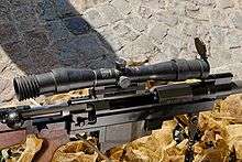
The former Warsaw Pact members produce military telescopic sights for their designated marksmen and developed a range finding reticle based on the height of an average human. This stadiametric rangefinder reticle was originally used in the Russian PSO-1 4×24 rifle scope and is calibrated for ranging a 1.7 m tall target from 200 m to 1000 m. The target base has to be lined up on the horizontal line of the range-finding scale and the target top point has to touch the upper (dotted) line of the scale without clearance. The digit under which this line up occurs determines the distance to the target. The PSO-1 basic design and stadiametric rangefinder are also found in the POSP and other telescopic sight models.
The Israeli military began widespread use of telescopic sights by ordinary infantrymen to increase hit probability (especially in dim light) and extend effective range of standard issue infantry rifles. Palestinian militants in the al Aqsa Intifada likewise found that adding an inexpensive scope to an AK-47 increased its effectiveness.
Today, several militaries issue telescopic sights to their infantry, usually compact, low-magnification sights suitable for snap-shooting. The US military issues the Advanced Combat Optical Gunsight (ACOG), designed to be used on the M16 rifle and M4 carbine. American soldiers in Iraq and Afghanistan frequently purchase their own combat optics and carry them from home. The British army fields the SA80 rifle with the SUSAT 4× optical sight as standard issue. The Canadian Forces standard C7 rifle has a 3.4× Elcan C79 optical sight. Both Austria and Australia field variants of the Austrian Steyr AUG which has built an integral 1.5× optical sight since its deployment in the late 1970s. The German Army G36 assault rifles have a more or less built in dual combat sighting system consisting of a ZF 3x4° telescopic sight combined with an unmagnified electronic red dot sight. The dual combat sighting system weighs 30 g (1.1 oz) due to a housing made out of glass fibre reinforced polyamide. All German G36 rifles are adapted to use the Hensoldt NSA 80 II third-generation night sight, which clamps into the G36 carry handle adapter in front of the optical sight housing and mates with the rifle's standard dual combat sighting system.
See also
References
- ↑ "The 1860's Target Rifle". Snipercountry.com. 29 June 2000. Archived from the original on 24 October 2010. Retrieved 26 November 2010.
- ↑ "Science Civil War Report". Fisher.k12.il.us. Retrieved 26 November 2010.
- ↑ "Parker Hale and Davidson telescopic sight". Civilwarguns.com. Retrieved 26 November 2010.
- ↑ "Davidson telescopic sight". Thefiringline.com. Retrieved 26 November 2010.
- ↑ "Important Dates in Gun History, Compiled and Researched by the American Firearms Institute". Americanfirearms.org. Archived from the original on 18 November 2010. Retrieved 26 November 2010.
- ↑ "Introduction to Optics 2nd ed.", pp.141–142, Pedrotti & Pedrotti, Prentice-Hall 1993
- ↑ http://mil-dot.com How to Get the Most Out of Your Mil-Dot Reticle
- ↑ Fred A. Carson, Basic optics and optical instruments, page 4-33
- ↑ "Telescopic sights for handheld weapons". Zeiss. Retrieved 26 November 2010.
- ↑ "U.S. Optics Inc.". Usoptics.com. Retrieved 26 November 2010.
- ↑ Sidewheel Scope Model for Parallax Error article on buying rifle scopes
- ↑ Can I have a Bullet Drop Compensation (BDC) dial made for my scope?
- ↑ Mac 1 Airgun "drooper" mounts
- ↑ Pyramid Air article on adjustable scope bases
- ↑ Jon R. Sondra (October 1997). "Swarovski promotion includes free Remington and Browning rifles – Swarovski AG rifle-scope marketing campaign". Shooting Industry.
- ↑ LRS 2-12x50
- ↑ "Barrett BORS Manual" (PDF). Barrettrifles.com. Retrieved 26 November 2010.
- ↑ "6-24x72 SAM telescopic sight" (PDF). Archived from the original (PDF) on 5 November 2014. Retrieved 26 November 2010.
- ↑ "EAW scope mounts". Eaw.de. Archived from the original on 15 November 2010. Retrieved 2010-11-26.
- ↑ "EAW Katalog 2010" (PDF). Archived from the original (PDF) on 18 July 2011. Retrieved 2010-11-26.
- ↑ Weapons & Sensors, NATO Army Armaments Group
- ↑ High-speed video of a Schmidt & Bender PMII telescopic sight, mounting and barrel flexing on a .50 BMG Accuracy International AS50.
- ↑ 2014 field test focused on long-range, tactical rifle scopes in the $1,500+ price range
External links
| Wikimedia Commons has media related to Telescopic sights. |
- MILS and MOA, by Robert J. Simeone
- AllWorldWars.com, Description of 2-inch Telescopic Sights Model 1906, designed by Warner & Swasey Co., Cleveland