Total harmonic distortion analyzer
A total harmonic distortion analyzer calculates the total harmonic content of a sinewave with some distortion, expressed as total harmonic distortion (THD). A typical application is to determine the THD of an amplifier by using a very-low-distortion sinewave input and examining the output. The figure measured will include noise, and any contribution from imperfect filtering out of the fundamental frequency. Harmonic-by-harmonic measurement, without wideband noise, can be measured by a more complex wave analyser.
Another application is measurement of the effectiveness of an electronic filter with extremely narrow passband, such as a notch filter in a parametric equalizer.
Types of THD meter
There are several types of distortion analyzers:
- Fundamental suppression[1]
- Heterodyne type[2]
- Tuned circuit
- Spectrum analyzer
Fundamental suppression analyzer
This type of THD analyzer filters out the fundamental frequency of a signal with a notch filter, leaving only distortion products plus noise; the ratio of this remnant to the signal amplitude is the THD.
Principles of operation

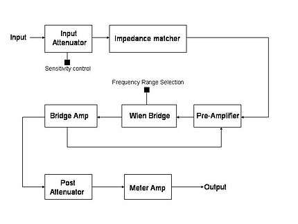
A fundamental suppression analyzer consists of three main sections: input section with impedance matcher, a notch filter and amplifier section, and an output metering circuit. Negative feedback from the bridge amplifier to the pre-amp section may be applied to enable the rejection circuit to work more accurately.
Working of a typical unit
The input is impedance-matched with the rejection circuit with the help of an attenuator and an impedance matcher. This signal is then pre-amplified to a desired level. The following section consists of a Wien bridge notch filter tuned to reject the fundamental frequency and balanced for minimum output by adjusting the bridge controls. The output, which is the remaining signal after the fundamental has been suppressed, is amplified to a measurable level. A feedback loop from the bridge amplifier output to the pre-amp input helps to eliminate any remaining contribution from the fundamental frequency. The output from these blocks is measured, typically using an instrumentation amplifier driving an analog or digital meter. The voltage at the meter is due to the harmonic distortion products plus noise.
See also
- Distortion
- Audio quality measurement
- ITU-R 468 noise weighting
- Loudspeaker measurement
- Alignment level
References
- ↑ Bakshi, Bakshi & Bakshi 2009, pp. 4-23 to 4-26.
- ↑ Bakshi, Bakshi & Bakshi 2009, pp. 4-26 to 4-??.
- Bakshi, U. A.; Bakshi, A. V.; Bakshi, K. A. (2009), Electronic Measurements and Instrumentation (second revised ed.), Pune, India: Technical Publications Pune, ISBN 978-81-8431-665-0
- Helfrick, Albert D.; Cooper, William D. (1989), Modern Electronic Instrumentation & Measurement Techniques, Prentice Hall, ISBN 978-0-13-593294-0
- Roddy, Dennis; Coolen, John (1977), Electronic Communications, Reston Publishing Co., ISBN 978-0-87909-224-5