SCADA
| Part of a series of articles on |
| Manufacturing |
|---|
 |
| Manufacturing methods |
| Improvement methods |
| Information and communication |
| Process control |
Supervisory control and data acquisition (SCADA) is a control system architecture that uses computers, networked data communications and graphical user interfaces for high-level process supervisory management, but uses other peripheral devices such as programmable logic controllers and discrete PID controllers to interface to the process plant or machinery. The operator interfaces which enable monitoring and the issuing of process commands, such as controller set point changes, are handled through the SCADA supervisory computer system. However, the real-time control logic or controller calculations are performed by networked modules which connect to the field sensors and actuators.
The SCADA concept was developed as a universal means of remote access to a variety of local control modules, which could be from different manufacturers allowing access through standard automation protocols. In practice, large SCADA systems have grown to become very similar to distributed control systems in function, but using multiple means of interfacing with the plant. They can control large-scale processes that can include multiple sites, and work over large distances.[1] It is one of the most commonly-used types of industrial control systems, however there are concerns about SCADA systems being vulnerable to cyberwarfare/cyberterrorism attacks.[2]
The SCADA concept in control operations

The key attribute of a SCADA system is its ability to perform a supervisory operation over a variety of other proprietary devices.
The accompanying diagram is a general model which shows functional manufacturing levels using computerised control.
Referring to the diagram;
- Level 0 contains the field devices such as flow and temperature sensors, and final control elements, such as control valves
- Level 1 contains the industrialised Input/Output (I/O) modules, and their associated distributed electronic processors.
- Level 2 contains the supervisory computers, which collate information from processor nodes on the system, and provide the operator control screens.
- Level 3 is the production control level, which does not directly control the process, but is concerned with monitoring production and targets
- Level 4 is the production scheduling level.
Level 1 contains the PLCs (Programmable Logic Controllers) or RTUs (Remote Terminal Units)
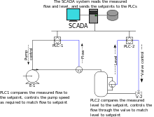
Level 2 contains the SCADA software and computing platform. The SCADA software exists only at this supervisory level as control actions are performed automatically by RTUs or PLCs. SCADA control functions are usually restricted to basic overriding or supervisory level intervention. For example, a PLC may control the flow of cooling water through part of an industrial process to a set point level, but the SCADA system software will allow operators to change the set points for the flow. The SCADA also enables alarm conditions, such as loss of flow or high temperature, to be displayed and recorded. A feedback control loop is directly controlled by the RTU or PLC, but the SCADA software monitors the overall performance of the loop.
Levels 3 and 4 are not strictly process control in the traditional sense, but are where production control and scheduling takes place.
Data acquisition begins at the RTU or PLC level and includes instrumentation readings and equipment status reports that are communicated to level 2 SCADA as required. Data is then compiled and formatted in such a way that a control room operator using the HMI (Human Machine Interface) can make supervisory decisions to adjust or override normal RTU (PLC) controls. Data may also be fed to a Historian, often built on a commodity Database Management System, to allow trending and other analytical auditing.
SCADA systems typically use a tag database, which contains data elements called tags or points, which relate to specific instrumentation or actuators within the process system according to such as the Piping and instrumentation diagram. Data is accumulated against these unique process control equipment tag references.
Examples of use

SCADA is very scaleable, and cost-effective systems both large and small can be built using the SCADA concept. They can range from just tens to thousands of process loops, depending on the application. Example processes include industrial, infrastructure, and facility-based processes, as described below:
- Industrial processes include manufacturing, Process control, power generation, fabrication, and refining, and may run in continuous, batch, repetitive, or discrete modes.
- Infrastructure processes may be public or private, and include water treatment and distribution, wastewater collection and treatment, oil and gas pipelines, electrical power transmission and distribution, and wind farms.
- Facility processes, including buildings, airports, ships, and space stations. They monitor and control heating, ventilation, and air conditioning systems (HVAC), access, and energy consumption.
However, SCADA systems may have security vulnerabilities, so the systems should be evaluated to identify risks and solutions implemented to mitigate those risks.[3]
SCADA system components

A SCADA system usually consists of the following main elements:
Supervisory computers
This is the core of the SCADA system, gathering data on the process and sending control commands to the field connected devices. It refers to the computer and software responsible for communicating with the field connection controllers, which are RTUs and PLCs, and includes the HMI software running on operator workstations. In smaller SCADA systems, the supervisory computer may be composed of a single PC, in which case the HMI is a part of this computer. In larger SCADA systems, the master station may include several HMIs hosted on client computers, multiple servers for data acquisition, distributed software applications, and disaster recovery sites. To increase the integrity of the system the multiple servers will often be configured in a dual-redundant or hot-standby formation providing continuous control and monitoring in the event of a server malfunction or breakdown.
Remote terminal units
Remote terminal units, also known as (RTUs), connect to sensors and actuators in the process, and are networked to the supervisory computer system. RTUs are "intelligent I/O" and often have embedded control capabilities such as ladder logic in order to accomplish boolean logic operations.[4]
Programmable logic controllers
Also known as PLCs, these are connected to sensors and actuators in the process, and are networked to the supervisory system in the same way as RTUs. PLCs have more sophisticated embedded control capabilities than RTUs, and are programmed in one or more IEC 61131-3 programming languages. PLCs are often used in place of RTUs as field devices because they are more economical, versatile, flexible and configurable.
Communication infrastructure
This connects the supervisory computer system to the remote terminal units (RTUs) and PLCs, and may use industry standard or manufacturer proprietary protocols. Both RTUs and PLCs operate autonomously on the near-real time control of the process, using the last command given from the supervisory system. Failure of the communications network does not necessarily stop the plant process controls, and on resumption of communications, the operator can continue with monitoring and control. Some critical systems will have dual redundant data highways, often cabled via diverse routes.
Human-Machine Interface (HMI)
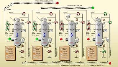
The HMI system is the operator window of the supervisory system. It presents plant information to the operating personnel graphically in the form of mimic diagrams, which are a schematic representation of the plant being controlled, and alarm and event logging pages. The HMI is linked to the SCADA supervisory computer to provide live data to drive the mimic diagrams, alarm displays and trending graphs. In many installations the HMI is the graphical user interface for the operator, collects all data from external devices, creates reports, performs alarming, sends notifications, etc.
Mimic diagrams consist of line graphics and schematic symbols to represent process elements, or may consist of digital photographs of the process equipment overlain with animated symbols.
Supervisory operation of the plant is is by means of the HMI, with operators issuing commands using mouse pointers, keyboards and touch screens. For example, a symbol of a pump can show the operator that the pump is running and a flow meter symbol can show how much fluid it is pumping through the pipe. The operator can switch the pump off from the mimic by a mouse click or screen touch. The HMI will show the flow rate of the fluid in the pipe decrease in real time.
The HMI package for a SCADA system typically includes a drawing program that the operators or system maintenance personnel use to change the way these points are represented in the interface. These representations can be as simple as an on-screen traffic light, which represents the state of an actual traffic light in the field, or as complex as a multi-projector display representing the position of all of the elevators in a skyscraper or all of the trains on a railway.
A "historian", is a software service within the HMI which accumulates time-stamped data, events, and alarms in a database which can be queried or used to populate graphic trends in the HMI. The historian is a client that requests data from a data acquisition server.[5]
Alarm handling
An important part of most SCADA implementations is alarm handling. The system monitors whether certain alarm conditions are satisfied, to determine when an alarm event has occurred. Once an alarm event has been detected, one or more actions are taken (such as the activation of one or more alarm indicators, and perhaps the generation of email or text messages so that management or remote SCADA operators are informed). In many cases, a SCADA operator may have to acknowledge the alarm event; this may deactivate some alarm indicators, whereas other indicators remain active until the alarm conditions are cleared.
Alarm conditions can be explicit—for example, an alarm point is a digital status point that has either the value NORMAL or ALARM that is calculated by a formula based on the values in other analogue and digital points—or implicit: the SCADA system might automatically monitor whether the value in an analogue point lies outside high and low- limit values associated with that point.
Examples of alarm indicators include a siren, a pop-up box on a screen, or a coloured or flashing area on a screen (that might act in a similar way to the "fuel tank empty" light in a car); in each case, the role of the alarm indicator is to draw the operator's attention to the part of the system 'in alarm' so that appropriate action can be taken.
PLC/RTU programming
"Smart" RTUs, or standard PLCs, are capable of autonomously executing simple logic processes without involving the supervisory computer. They employ standardized control programming languages such as under, IEC 61131-3 (a suite of 5 programming languages including function block, ladder, structured text, sequence function charts and instruction list), is frequently used to create programs which run on these RTUs and PLCs. Unlike a procedural language such as the C programming language or FORTRAN, IEC 61131-3 has minimal training requirements by virtue of resembling historic physical control arrays. This allows SCADA system engineers to perform both the design and implementation of a program to be executed on an RTU or PLC.
A programmable automation controller (PAC) is a compact controller that combines the features and capabilities of a PC-based control system with that of a typical PLC. PACs are deployed in SCADA systems to provide RTU and PLC functions. In many electrical substation SCADA applications, "distributed RTUs" use information processors or station computers to communicate with digital protective relays, PACs, and other devices for I/O, and communicate with the SCADA master in lieu of a traditional RTU.
SCADA and PLC commercial integration
Since about 1998, virtually all major PLC manufacturers have offered integrated HMI/SCADA systems, many of them using open and non-proprietary communications protocols. Numerous specialized third-party HMI/SCADA packages, offering built-in compatibility with most major PLCs, have also entered the market, allowing mechanical engineers, electrical engineers and technicians to configure HMIs themselves, without the need for a custom-made program written by a software programmer. The Remote Terminal Unit (RTU) connects to physical equipment. Typically, an RTU converts the electrical signals from the equipment to digital values such as the open/closed status from a switch or a valve, or measurements such as pressure, flow, voltage or current. By converting and sending these electrical signals out to equipment the RTU can control equipment, such as opening or closing a switch or a valve, or setting the speed of a pump.
Communication infrastructure and methods
SCADA systems have traditionally used combinations of radio and direct wired connections, although SONET/SDH is also frequently used for large systems such as railways and power stations. The remote management or monitoring function of a SCADA system is often referred to as telemetry. Some users want SCADA data to travel over their pre-established corporate networks or to share the network with other applications. The legacy of the early low-bandwidth protocols remains, though.
SCADA protocols are designed to be very compact. Many are designed to send information only when the master station polls the RTU. Typical legacy SCADA protocols include Modbus RTU, RP-570, Profibus and Conitel. These communication protocols, with the exception of Modbus (Modbus has been made open by Schneider Electric, and is now managed by the modbus.org), are all SCADA-vendor specific but are widely adopted and used. Standard protocols are IEC 60870-5-101 or 104, IEC 61850 and DNP3. These communication protocols are standardized and recognized by all major SCADA vendors. Many of these protocols now contain extensions to operate over TCP/IP. Although the use of conventional networking specifications, such as TCP/IP, blurs the line between traditional and industrial networking, they each fulfill fundamentally differing requirements.[6]
With increasing security demands (such as North American Electric Reliability Corporation (NERC) and Critical Infrastructure Protection (CIP) in the US), there is increasing use of satellite-based communication. This has the key advantages that the infrastructure can be self-contained (not using circuits from the public telephone system), can have built-in encryption, and can be engineered to the availability and reliability required by the SCADA system operator. Earlier experiences using consumer-grade VSAT were poor. Modern carrier-class systems provide the quality of service required for SCADA.[7]
RTUs and other automatic controller devices were developed before the advent of industry wide standards for interoperability. The result is that developers and their management created a multitude of control protocols. Among the larger vendors, there was also the incentive to create their own protocol to "lock in" their customer base. A list of automation protocols is compiled here.
OLE for process control (OPC) can connect different hardware and software, allowing communication even between devices originally not intended to be part of an industrial network.
SCADA architecture development
SCADA systems have evolved through four generations as follows:[8][9][10]
First generation: "monolithic"
Early SCADA system computing was done by large minicomputers. Common network services did not exist at the time SCADA was developed. Thus SCADA systems were independent systems with no connectivity to other systems. The communication protocols used were strictly proprietary at that time. The first-generation SCADA system redundancy was achieved using a back-up mainframe system connected to all the Remote Terminal Unit sites and was used in the event of failure of the primary mainframe system.[11] Some first generation SCADA systems were developed as "turn key" operations that ran on minicomputers such as the PDP-11 series made by the Digital Equipment Corporation..
Second generation: "distributed"
SCADA information and command processing was distributed across multiple stations which were connected through a LAN. Information was shared in near real time. Each station was responsible for a particular task, which reduced the cost as compared to First Generation SCADA. The network protocols used were still not standardized. Since these protocols were proprietary, very few people beyond the developers knew enough to determine how secure a SCADA installation was. Security of the SCADA installation was usually overlooked.[11]
Third generation: "networked"
Similar to a distributed architecture, any complex SCADA can be reduced to simplest components and connected through communication protocols. In the case of a networked design, the system may be spread across more than one LAN network called a process control network (PCN) and separated geographically. Several distributed architecture SCADAs running in parallel, with a single supervisor and historian, could be considered a network architecture. This allows for a more cost effective solution in very large scale systems.
Fourth generation: "Internet of things"
With the commercial availability of cloud computing, SCADA systems have increasingly adopted Internet of Things technology to significantly reduce infrastructure costs and increase ease of maintenance and integration. As a result, SCADA systems can now report state in near real-time and use the horizontal scale available in cloud environments to implement more complex control algorithms than are practically feasible to implement on traditional programmable logic controllers.[12][13] Further, the use of open network protocols such as TLS inherent in the Internet of Things technology, provides a more readily comprehensible and manageable security boundary than the heterogeneous mix of proprietary network protocols typical of many decentralized SCADA implementations. One such example of this technology is an innovative approach to rainwater harvesting through the implementation of real time controls (RTC).
This decentralization of data also requires a different approach to SCADA than traditional PLC based programs. When a SCADA system is used locally, the preferred methodology involves binding the graphics on the user interface to the data stored in specific PLC memory addresses. However, when the data comes from a disparate mix of sensors, controllers and databases (which may be local or at varied connected locations), the typical 1 to 1 mapping becomes problematic. A solution to this is data modeling, a concept derived from object oriented programming.[14]
In a data model, a virtual representation of each device is constructed in the SCADA software. These virtual representations (“models”) can contain not just the address mapping of the device represented, but also any other pertinent information (web based info, database entries, media files, etc.) that may be used by other facets of the SCADA/IoT implementation. As the increased complexity of the Internet of Things renders traditional SCADA increasingly “house-bound,” and as communication protocols evolve to favor platform-independent, service-oriented architecture (such as OPC UA),[15] it is likely that more SCADA software developers will implement some form of data modeling.
Security issues
SCADA systems that tie together decentralized facilities such as power, oil, gas pipelines, water distribution and wastewater collection systems were designed to be open, robust, and easily operated and repaired, but not necessarily secure.[16] The move from proprietary technologies to more standardized and open solutions together with the increased number of connections between SCADA systems, office networks and the Internet has made them more vulnerable to types of network attacks that are relatively common in computer security. For example, United States Computer Emergency Readiness Team (US-CERT) released a vulnerability advisory[17] that allowed unauthenticated users to download sensitive configuration information including password hashes on an Inductive Automation Ignition system utilizing a standard attack type leveraging access to the Tomcat Embedded Web server. Security researcher Jerry Brown submitted a similar advisory regarding a buffer overflow vulnerability[18] in a Wonderware InBatchClient ActiveX control. Both vendors made updates available prior to public vulnerability release. Mitigation recommendations were standard patching practices and requiring VPN access for secure connectivity. Consequently, the security of some SCADA-based systems has come into question as they are seen as potentially vulnerable to cyber attacks.[2][19][20]
In particular, security researchers are concerned about:
- the lack of concern about security and authentication in the design, deployment and operation of some existing SCADA networks
- the belief that SCADA systems have the benefit of security through obscurity through the use of specialized protocols and proprietary interfaces
- the belief that SCADA networks are secure because they are physically secured
- the belief that SCADA networks are secure because they are disconnected from the Internet.
SCADA systems are used to control and monitor physical processes, examples of which are transmission of electricity, transportation of gas and oil in pipelines, water distribution, traffic lights, and other systems used as the basis of modern society. The security of these SCADA systems is important because compromise or destruction of these systems would impact multiple areas of society far removed from the original compromise. For example, a blackout caused by a compromised electrical SCADA system would cause financial losses to all the customers that received electricity from that source. How security will affect legacy SCADA and new deployments remains to be seen.
There are many threat vectors to a modern SCADA system. One is the threat of unauthorized access to the control software, whether it is human access or changes induced intentionally or accidentally by virus infections and other software threats residing on the control host machine. Another is the threat of packet access to the network segments hosting SCADA devices. In many cases, the control protocol lacks any form of cryptographic security, allowing an attacker to control a SCADA device by sending commands over a network. In many cases SCADA users have assumed that having a VPN offered sufficient protection, unaware that security can be trivially bypassed with physical access to SCADA-related network jacks and switches. Industrial control vendors suggest approaching SCADA security like Information Security with a defense in depth strategy that leverages common IT practices.[21]
The reliable function of SCADA systems in our modern infrastructure may be crucial to public health and safety. As such, attacks on these systems may directly or indirectly threaten public health and safety. Such an attack has already occurred, carried out on Maroochy Shire Council's sewage control system in Queensland, Australia.[22] Shortly after a contractor installed a SCADA system in January 2000, system components began to function erratically. Pumps did not run when needed and alarms were not reported. More critically, sewage flooded a nearby park and contaminated an open surface-water drainage ditch and flowed 500 meters to a tidal canal. The SCADA system was directing sewage valves to open when the design protocol should have kept them closed. Initially this was believed to be a system bug. Monitoring of the system logs revealed the malfunctions were the result of cyber attacks. Investigators reported 46 separate instances of malicious outside interference before the culprit was identified. The attacks were made by a disgruntled ex-employee of the company that had installed the SCADA system. The ex-employee was hoping to be hired by the utility full-time to maintain the system.
In April 2008, the Commission to Assess the Threat to the United States from Electromagnetic Pulse (EMP) Attack issued a Critical Infrastructures Report which discussed the extreme vulnerability of SCADA systems to an electromagnetic pulse (EMP) event. After testing and analysis, the Commission concluded: "SCADA systems are vulnerable to an EMP event. The large numbers and widespread reliance on such systems by all of the Nation’s critical infrastructures represent a systemic threat to their continued operation following an EMP event. Additionally, the necessity to reboot, repair, or replace large numbers of geographically widely dispersed systems will considerably impede the Nation’s recovery from such an assault."[23]
Many vendors of SCADA and control products have begun to address the risks posed by unauthorized access by developing lines of specialized industrial firewall and VPN solutions for TCP/IP-based SCADA networks as well as external SCADA monitoring and recording equipment. The International Society of Automation (ISA) started formalizing SCADA security requirements in 2007 with a working group, WG4. WG4 "deals specifically with unique technical requirements, measurements, and other features required to evaluate and assure security resilience and performance of industrial automation and control systems devices".[24]
The increased interest in SCADA vulnerabilities has resulted in vulnerability researchers discovering vulnerabilities in commercial SCADA software and more general offensive SCADA techniques presented to the general security community.[25] In electric and gas utility SCADA systems, the vulnerability of the large installed base of wired and wireless serial communications links is addressed in some cases by applying bump-in-the-wire devices that employ authentication and Advanced Encryption Standard encryption rather than replacing all existing nodes.[26]
In June 2010, anti-virus security company VirusBlokAda reported the first detection of malware that attacks SCADA systems (Siemens' WinCC/PCS 7 systems) running on Windows operating systems. The malware is called Stuxnet and uses four zero-day attacks to install a rootkit which in turn logs into the SCADA's database and steals design and control files.[27][28] The malware is also capable of changing the control system and hiding those changes. The malware was found on 14 systems, the majority of which were located in Iran.[29]
In October 2013 National Geographic released a docudrama titled, "American Blackout" which dealt with a large-scale cyber attack on SCADA and the United States' electrical grid.[30]
See also
| Wikimedia Commons has media related to SCADA. |
References
- ↑ Boys, Walt (18 August 2009). "Back to Basics: SCADA". Automation TV: Control Global - Control Design.
- 1 2 "Cyberthreats, Vulnerabilities and Attacks on SCADA Networks" (PDF). Rosa Tang, berkeley.edu. Archived from the original (PDF) on 13 August 2012. Retrieved 1 August 2012.
- ↑ Boyer, Stuart A. (2010). SCADA Supervisory Control and Data Acquisition. USA: ISA - International Society of Automation. p. 179. ISBN 978-1-936007-09-7.
- ↑ Jeff Hieb (2008). Security Hardened Remote Terminal Units for SCADA Networks. University of Louisville.
- ↑ Aquino-Santos, Raul (30 November 2010). Emerging Technologies in Wireless Ad-hoc Networks: Applications and Future Development: Applications and Future Development. IGI Global. pp. 43–. ISBN 978-1-60960-029-7.
- ↑ "Introduction to Industrial Control Networks" (PDF). IEEE Communications Surveys and Tutorials. 2012.
- ↑ Bergan, Christian (August 2011). "Demystifying Satellite for the Smart Grid: Four Common Misconceptions". Electric Light & Powers. Utility Automation & Engineering T&D. Tulsa, OK: PennWell. 16 (8). Four. Retrieved 2 May 2012.
satellite is a cost-effective and secure solution that can provide backup communications and easily support core smart grid applications like SCADA, telemetry, AMI backhaul and distribution automation
- ↑ OFFICE OF THE MANAGER NATIONAL COMMUNICATIONS SYSTEMctober 2004. "Supervisory Control and Data Acquisition (SCADA) Systems" (PDF). NATIONAL COMMUNICATIONS SYSTEM.
- ↑ "SCADA Systems april 2014".
- ↑ J. Russel. "A Brief History of SCADA/EMS (2015)".
- 1 2 Security Hardened Remote Terminal Units for SCADA Networks. ProQuest. 2008. pp. 12–. ISBN 978-0-549-54831-7.
- ↑ "SCADA as a service approach for interoperability of micro-grid platforms". Sustainable Energy, Grids and Network. 2016. doi:10.1016/j.segan.2016.08.001.
- ↑ How The "Internet Of Things" Is Turning Cities Into Living Organisms Retrieved September 16, 2013
- ↑ "The History of Data Modeling". Exforsys Inc. 11 January 2007.
- ↑ "CIM and OPC UA for interoperability of micro-grid platforms". Proceeding of the IEEE ISGT 2016 Conference. 6 September 2016.
- ↑ Boyes, Walt (2011). Instrumentation Reference Book, 4th Edition. USA: Butterworth-Heinemann. p. 27. ISBN 0-7506-8308-2.
- ↑ "ICSA-11-231-01—INDUCTIVE AUTOMATION IGNITION INFORMATION DISCLOSURE VULNERABILITY" (PDF). 19 Aug 2011. Retrieved 21 Jan 2013.
- ↑ "ICSA-11-094-01—WONDERWARE INBATCH CLIENT ACTIVEX BUFFER OVERFLOW" (PDF). 13 Apr 2011. Retrieved 26 Mar 2013.
- ↑ D. Maynor and R. Graham (2006). "SCADA Security and Terrorism: We're Not Crying Wolf" (PDF).
- ↑ Robert Lemos (26 July 2006). "SCADA system makers pushed toward security". SecurityFocus. Retrieved 9 May 2007.
- ↑ "Industrial Security Best Practices" (PDF). Rockwell Automation. Retrieved 26 Mar 2013.
- ↑ Slay, J.; Miller, M. (November 2007). "Chpt 6: Lessons Learned from the Maroochy Water Breach". Critical infrastructure protection (Online-Ausg. ed.). Springer Boston. pp. 73–82. ISBN 978-0-387-75461-1. Retrieved 2 May 2012.
- ↑ http://www.empcommission.org/docs/A2473-EMP_Commission-7MB.pdf
- ↑ "Security for all". InTech. June 2008. Retrieved 2 May 2012.
- ↑ "SCADA Security – Generic Electric Grid Malware Design". Archived from the original on 7 January 2009.
- ↑ KEMA, Inc. (November 2006). "Substation Communications: Enabler of Automation / An Assessment of Communications Technologies". UTC – United Telecom Council: 3–21.
- ↑ Mills, Elinor (21 July 2010). "Details of the first-ever control system malware (FAQ)". CNET. Retrieved 21 July 2010.
- ↑ "SIMATIC WinCC / SIMATIC PCS 7: Information concerning Malware / Virus / Trojan". Siemens. 21 July 2010. Retrieved 22 July 2010.
malware (trojan) which affects the visualization system WinCC SCADA.
- ↑ "Siemens: Stuxnet worm hit industrial systems". Retrieved 16 September 2010.
- ↑ "American Blackout". National Geographic Channel. Retrieved 14 October 2016.