Solid-state relay
A solid-state relay (SSR) is an electronic switching device that switches on or off when a small external voltage is applied across its control terminals. SSRs consist of a sensor which responds to an appropriate input (control signal), a solid-state electronic switching device which switches power to the load circuitry, and a coupling mechanism to enable the control signal to activate this switch without mechanical parts. The relay may be designed to switch either AC or DC to the load. It serves the same function as an electromechanical relay, but has no moving parts.
Packaged solid-state relays use power semiconductor devices such as thyristors and transistors, to switch currents up to around a hundred amperes. Solid-state relays have fast switching speeds compared with electromechanical relays, and have no physical contacts to wear out. Application of solid-state relays must consider their lower ability to withstand momentary overload, compared with electromechanical contacts, and their higher "on" state resistance. Unlike an electromechanical relay, a solid-state relay provides only limited switching arrangements (SPST switching).
Coupling
The control signal must be coupled to the controlled circuit in a way which provides galvanic isolation between the two circuits.
Many SSRs use optical coupling. The control voltage energizes an internal LED which illuminates and switches on a photo-sensitive diode (photo-voltaic); the diode current turns on a back-to-back thyristor, SCR, or MOSFET to switch the load. The optical coupling allows the control circuit to be electrically isolated from the load.
Operation
An SSR based on a single MOSFET, or multiple MOSFETs in a paralleled array, can work well for DC loads. MOSFETs have an inherent substrate diode that conducts in the reverse direction, so a single MOSFET cannot block current in both directions. For AC (bi-directional) operation two MOSFETs are arranged back-to-back with their source pins tied together. Their drain pins are connected to either side of the output. The substrate diodes are alternately reverse biased to block current when the relay is off. When the relay is on, the common source is always riding on the instantaneous signal level and both gates are biased positive relative to the source by the photo-diode.
It is common to provide access to the common source so that multiple MOSFETs can be wired in parallel if switching a DC load. Usually a network is provided to speed the turn-off of the MOSFET when the control input is removed.
In AC circuits, SCR or TRIAC relays inherently switch off at the points of zero load current. The circuit will never be interrupted in the middle of a sine wave peak, preventing the large transient voltages that would otherwise occur due to the sudden collapse of the magnetic field around the inductance. This feature is called zero-crossover switching.
Parameters
SSRs are characterised by a number of parameters including the required activating input voltage, current, output voltage and current, whether it is AC or DC, voltage drop or resistance affecting output current, thermal resistance, and thermal and electrical parameters for safe operating area (e.g., derating according to thermal resistance when repeatedly switching large currents).
Advantages over mechanical relays
Most of the relative advantages of solid state and electromechanical relays are common to all solid-state as against electromechanical devices.
- Slimmer profile, allowing tighter packing.
- Totally silent operation.
- SSRs switch faster than electromechanical relays; the switching time of a typical optically coupled SSR is dependent on the time needed to power the LED on and off - of the order of microseconds to milliseconds.
- Increased lifetime, even if it is activated many times, as there are no moving parts to wear and no contacts to pit or build up carbon.
- Output resistance remains constant regardless of amount of use.
- Clean, bounceless operation.
- No sparking, allows it to be used in explosive environments, where it is critical that no spark is generated during switching.
- Inherently smaller than a mechanical relay of similar specification (if desired may have the same "casing" form factor for interchangeability).
- Much less sensitive to storage and operating environment factors such as mechanical shock, vibration, humidity, and external magnetic fields.
Disadvantages
- Voltage/current characteristic of semiconductor rather than mechanical contacts:
- When closed, higher resistance (generating heat), and increased electrical noise
- When open, lower resistance, and reverse leakage current (typically µA range)
- Voltage/current characteristic is not linear (not purely resistive), distorting switched waveforms to some extent. An electromechanical relay has the low ohmic (linear) resistance of the associated mechanical switch when activated, and the exceedingly high resistance of the air gap and insulating materials when open.
- Some types have polarity-sensitive output circuits. Electromechanical relays are not affected by polarity.
- Possibility of spurious switching due to voltage transients (due to much faster switching than mechanical relay)
- Isolated bias supply required for gate charge circuit
- Higher transient reverse recovery time (Trr) due to the presence of the body diode
- Tendency to fail "shorted" on their outputs, while electromechanical relay contacts tend to fail "open".
Images
|
|
 |
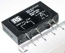
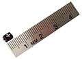 Miniature solid state relay. |
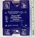
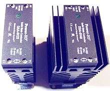 Solid state contactor. |
See also
References
External links
- A DC Fault Protection Circuit for Audio Amplifiers
- Solid state relay glossary of terminology
- National Instruments Solid State Relays
- Solid State Relays vs Electromechanical Relays