Shearing interferometer
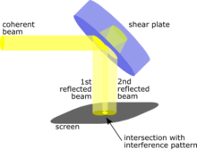
The shearing interferometer is an extremely simple means to observe interference and to use this phenomenon to test the collimation of light beams, especially from laser sources which have a coherence length which is usually a lot longer than the thickness of the shear plate (see graphics) so that the basic condition for interference is fulfilled.
Function
The testing device consists of a high-quality optical glass, like N-BK7, with extremely flat optical surfaces that are usually at a slight angle to each other. When a plane wave is incident at an angle of 45°, which gives maximum sensitivity, it is reflected two times. The two reflections are laterally separated due to the finite thickness of the plate and by the wedge. This separation is referred to as the shear and has given the instrument its name. The shear can also be produced by gratings, see External Links below.
Parallel-sided shear plates are sometimes used, but the interpretation of the interference fringes of wedged plates is relatively easy and straightforward. Wedged shear plates produce a graded path difference between the front and back surface reflections; as a consequence, a parallel beam of light produces a linear fringe pattern within the overlap.
With a plane wavefront incident, the overlap of the two reflected beams shows interference fringes with a spacing of , where is the wavelength of the beam, n the refractive index, and the wedge angle. The fringes are equally spaced and will be exactly perpendicular to the wedge orientation and parallel to a usually present wire cursor aligned along the beam axis in the shearing interferometer. The orientation of the fringes varies when the beam is not perfectly collimated. In the case of a noncollimated beam incident on a wedged shear plate, the path difference between the two reflected wavefronts is increased or decreased from the case of perfect collimation depending on the sign of the curvature. The pattern is then rotated and the beam's wavefront radius of curvature can be calculated: , with the shear distance, the fringe distance, the wavelength and the angular deviation of the fringe alignment from that of perfect collimation.[1]


See also
- List of types of interferometers
- Air-wedge shearing interferometer
- Spectral phase interferometry for direct electric-field reconstruction, a type of spectral shearing interferometry, which is similar in concept to the one in the present article, except that the shearing is performed in the frequency domain instead of laterally.
References
- ↑ Riley, M (1977). "Laser Beam Divergence Utilizing a Shearing Interferometer". Applied Optics. doi:10.1364/AO.16.002753. PMID 20174226.