Shear and moment diagram

Shear and bending moment diagrams are analytical tools used in conjunction with structural analysis to help perform structural design by determining the value of shear force and bending moment at a given point of a structural element such as a beam. These diagrams can be used to easily determine the type, size, and material of a member in a structure so that a given set of loads can be supported without structural failure. Another application of shear and moment diagrams is that the deflection of a beam can be easily determined using either the moment area method or the conjugate beam method.
Convention
Although these conventions are relative and any convention can be used if stated explicitly, practicing engineers have adopted a standard convention used in design practices.
Normal convention
The normal convention used in most engineering applications is to label a positive shear force one that spins an element clockwise (up on the left, and down on the right). Likewise the normal convention for a positive bending moment is to warp the element in a "u" shape manner (Clockwise on the left, and counterclockwise on the right). Another way to remember this is if the moment is bending the beam into a "smile" then the moment is positive, with compression at the top of the beam and tension on the bottom.[1]
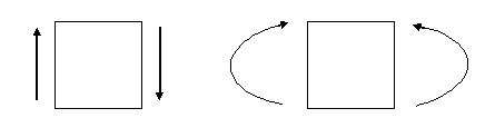
This convention was selected to simplify the analysis of beams. Since a horizontal member is usually analyzed from left to right and positive in the vertical direction is normally taken to be up, the positive shear convention was chosen to be up from the left, and to make all drawings consistent down from the right. The positive bending convention was chosen such that a positive shear force would tend to create a positive moment.
Alternative drawing convention
In structural engineering and in particular concrete design the positive moment is drawn on the tension side of the member. This convention puts the positive moment below the beam described above. A convention of placing moment diagram on the tension side allows for frames to be dealt with more easily and clearly. Additionally placing the moment on the tension side of the member shows the general shape of the deformation and indicates on which side of a concrete member rebar should be placed, as concrete is weak in tension.[2]
Calculating shear force and bending moment

With the loading diagram drawn the next step is to find the value of the shear force and moment at any given point along the element. For a horizontal beam one way to perform this is at any point to "chop off" the right end of the beam.
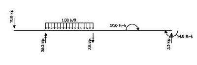
The example below includes a point load, a distributed load, and an applied moment. The supports include both hinged supports and a fixed end support. The first drawing shows the beam with the applied forces and displacement constraints. The second drawing is the loading diagram with the reaction values given without the calculations shown or what most people call a free body diagram. The third drawing is the shear force diagram and the fourth drawing is the bending moment diagram. For the bending moment diagram the normal sign convention was used. Below the moment diagram are the stepwise functions for the shear force and bending moment with the functions expanded to show the effects of each load on the shear and bending functions.
The example is illustrated using United States customary units. Point loads are expressed in kips (1 kip = 1000 lbf = 4.45 kN), distributed loads are expressed in k/ft (1 k/ft = 1 kip/ft = 14.6 kN/m), moments are expressed in ft-k (1 ft-k = 1 ft-kip = 1.356 kNm), and lengths are in ft (1 ft = 0.3048 m).
Step 1: Compute the reaction forces and moments

The first step obtaining the bending moment and shear force equations is to determine the reaction forces. This is done using a free body diagram of the entire beam.
The beam has three reaction forces, Ra, Rb at the two supports and Rc at the clamped end. The clamped end also has a reaction couple Mc. These four quantities have to be determined using two equations, the balance of forces in the beam and the balance of moments in the beam. Four unknowns cannot be found given two independent equations in these unknown variables and hence the beam is statically indeterminate. One way of solving this problem is to use the principle of linear superposition and break the problem up into the superposition of a number of statically determinate problems. The extra boundary conditions at the supports have to be incorporated into the superposed solution so that the deformation of the entire beam is compatible.
From the free-body diagram of the entire beam we have the two balance equations

Summing the forces, we have

and summing the moments around the free end (A) we have

We can solve these equations for Rb and Rc in terms of Ra and Mc :

and

If we sum moments about the first support from the left of the beam we have

If we plug in the expressions for Rb and Rc we get the trivial identity 0 = 0 which indicates that this equation is not independent of the previous two. Similarly, if we take moments around the second support, we have

Once again we find that this equation is not independent of the first two equations. We could also try to compute moments around the clamped end of the beam to get

This equation also turns out not to be linearly independent from the other two equations. Therefore, the beam is statically indeterminate and we will have to find the bending moments in segments of the beam as functions of Ra and Mc.
Step 2: Break beam into segments
After the reaction forces are found, you then break the beam into pieces. The location and number of external forces on the member determine the number and location of these pieces. The first piece always starts from one end and ends anywhere before the first external force.
Step 3: Compute shear forces and moments - first piece

Let V1 and M1 be the shear force and bending moment respectively in a cross-section of the first beam segment. As the section of the beam moves towards the point of application of the external force the magnitudes of the shear force and moment may change. This makes the shear force and bending moment a function of the position of cross-section (in this example x).
By summing the forces along this segment and summing the moments, the equations for the shear force and bending moment are obtained. These equations are:

and

Therefore,

Step 4: Compute shear forces and moments - second piece
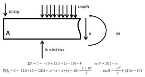
Taking the second segment, ending anywhere before the second internal force, we have

and

Therefore,

Notice that because the shear force is in terms of x, the moment equation is squared. This is due to the fact that the moment is the integral of the shear force. The tricky part of this moment is the distributed force. Since the force changes with the length of the segment, the force will be multiplied by the distance after 10 ft. i.e. (x-10) the moment location is defined in the middle of the distributed force, which is also changing. This is where (x+10)/2 is derived from.
Alternatively, we can take moments about the cross-section to get

Again, in this case,

Step 5: Compute shear forces and moments - third piece

Taking the third segment, and summing forces, we have

and summing moments about the cross-section, we get

Therefore,

and

Notice that the distributed force can now be considered one force of 15 kips acting in the middle of where it is positioned.
Step 6: Compute shear forces and moments - fourth piece

Taking the fourth and final segment, a balance of forces gives

and a balance of moments around the cross-section leads to

Solving for V4 and M4, we have

and

By plotting each of these equations on their intended intervals, you get the bending moment and shear force diagrams for this beam. In particular, at the clamped end of the beam, x = 50 and we have

Step 7: Compute deflections of the four segments
We now use the Euler-Bernoulli beam theory to compute the deflections of the four segments. The differential equation that relates the beam deflection (w) to the bending moment (M) is

where E is the Young's modulus and I is the area moment of inertia of the beam cross-section.
Substituting the expressions for M1, M2, M3, M4 into the beam equation and solving for the deflection gives us
![{\begin{aligned}w_{1}&={\frac {5}{3EI}}\,x^{3}+C_{1}+C_{2}\,x\\w_{2}&={\frac {1}{24EI}}\,x^{2}\,\left[x^{2}+600-4R_{a}(x-30)\right]+C_{3}+C_{4}\,x\\w_{3}&={\frac {1}{100EI}}\left[{\frac {x^{3}}{3}}(-625+30R_{a}-2M_{c})-50x^{2}(-675+30R_{a}-M_{c})\right]+C_{5}+C_{6}\,x\\w_{4}&={\frac {1}{100EI}}\left[{\frac {x^{3}}{3}}(-625+30R_{a}-2M_{c})-50x^{2}(-625+30R_{a}-M_{c})\right]+C_{7}+C_{8}\,x\end{aligned}}](../I/m/de1248a57cf4bba801978c7a7da1b22b8c1a89bc.svg)
Step 8: Apply boundary conditions
Now we will apply displacement boundary conditions for the four segments to determine the integration constants.
For the fourth segment of the beam, we consider the boundary conditions at the clamped end where w4 = dw/dx = 0 at x = 50. Solving for C7 and C8 gives

Therefore, we can express w4 as
![w_{4}=-{\frac {1}{300EI}}(x-50)^{2}\left[-5(6R_{a}-125)(x-50)+2M_{c}(x+25)\right]\,.](../I/m/31e10feae9ed25fff01c90a0351f1f1db417dc95.svg)
Now, w4 = w3 at x = 37.5 (the point of application of the external couple). Also, the slopes of the deflection curves at this point are the same, i.e., dw4/dx = dw3/dx. Using these boundary conditions and solving for C5 and C6, we get

Substitution of these constants into the expression for w3 gives us
![{\begin{aligned}w_{3}={\frac {1}{300EI}}{\Bigl [}&30R_{a}(-50+x)^{3}-2M_{c}(-50+x)^{2}(25+x)-\\&625(-141875+x(8400+(-162+x)x)){\Bigr ]}\,.\end{aligned}}](../I/m/6a64f0620dba6e76fcca895cd9f76d1fa3769826.svg)
Similarly, at the support between segments 2 and 3 where x = 25, w3 = w2 and dw3/dx = dw2/dx. Using these and solving for C3 and C4 gives

Therefore,
![{\begin{aligned}w_{2}={\frac {1}{24EI}}{\Bigl [}&-3125(-1645+4M_{c}+64R_{a})+\\&50(-4025+6M_{c}+120R_{a})x+120(5+R_{a})x^{2}-4R_{a}x^{3}+x^{4}{\Bigr ]}\,.\end{aligned}}](../I/m/6d985679e33b21a550b1db701bce05a1b06c84b1.svg)
At the support between segments 1 and 2, x = 10 and w1 = w2 and dw1/dx = dw2/dx. These boundary conditions give us

Therefore,
![w_{1}={\frac {5}{24EI}}\left[1026125-39450x+8x^{3}+20M_{c}(-125+3x)+480R_{a}(-85+3x)\right]\,.](../I/m/0dbf19d4039ba0b1376db0d69d51bbdba19bb107.svg)
Step 9: Solve for Mc and Ra
Because w2 = 0 at x = 25, we can solve for Mc in terms of Ra to get

Also, since w1 = 0 at x = 10, expressing the deflection in terms of Ra (after eliminating Mc) and solving for Ra, gives

Step 10: Plot bending moment and shear force diagrams

We can now calculate the reactions Rb and Rc, the bending moments M1, M2, M3, M4, and the shear forces V1, V2, V3, V4. These expressions can then be plotted as a function of length for each segment.
Relationship between shear force and bending moment
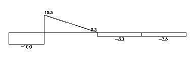
It is important to note the relationship between the two diagrams. The moment diagram is a visual representation of the area under the shear force diagram. That is, the moment is the integral of the shear force. If the shear force is constant over an interval, the moment equation will be in terms of x (linear). If the shear force is linear over an interval, the moment equation will be quadratic (parabolic).
Another note on the shear moment diagrams is that they show where external force and moments are applied. With no external forces, the piecewise functions should attach and show no discontinuity. The discontinuities on the graphs are the exact magnitude of either the external force or external moments that are applied. For example, at x = 10 on the shear force diagram, there is a gap between the two equations. This gap goes from -10 to 15.3. The length of this gap is 25.3, the exact magnitude of the external force at that point. At section 3 on the moment diagram, there is a discontinuity of 50. This is from the applied moment of 50 on the structure. The maximum and minimum vales on the graphs represent the max forces and moments that this beam will have under these circumstances.
Relationships between load, shear, and moment diagrams
Since this method can easily become unnecessarily complicated with relatively simple problems, it can be quite helpful to understand different relations between the loading, shear, and moment diagram. The first of these is the relationship between a distributed load on the loading diagram and the shear diagram. Since a distributed load varies the shear load according to its magnitude it can be derived that the slope of the shear diagram is equal to the magnitude of the distributed load. The relationship between distributed load and shear force magnitude is:[3]

Some direct results of this is that a shear diagram will have a point change in magnitude if a point load is applied to a member, and a linearly varying shear magnitude as a result of a constant distributed load. Similarly it can be shown that the slope of the moment diagram at a given point is equal to the magnitude of the shear diagram at that distance. The relationship between distributed shear force and bending moment is:[4]

A direct result of this is that at every point the shear diagram crosses zero the moment diagram will have a local maximum or minimum. Also if the shear diagram is zero over a length of the member, the moment diagram will have a constant value over that length. By calculus it can be shown that a point load will lead to a linearly varying moment diagram, and a constant distributed load will lead to a quadratic moment diagram.
Practical considerations
In practical applications the entire stepwise function is rarely written out. The only parts of the stepwise function that would be written out are the moment equations in a nonlinear portion of the moment diagram; this occurs whenever a distributed load is applied to the member. For constant portions the value of the shear and/or moment diagram is written right on the diagram, and for linearly varying portions of a member the beginning value, end value, and slope or the portion of the member are all that are required.[5]
See also
References
- ↑ Livermore, Carol; Henrik Schmidt, James Williams Jr., and Simona Socrate. "2.001 Mechanics & Materials I, Fall 2006.". Lecture 5: MIT OpenCourseWare: Massachusetts Institute of Technology. Retrieved 25 October 2013. Cite uses deprecated parameter
|coauthors=(help) - ↑ "Moment Diagram Sign Convention Poll". Eng-Tips Forum. Retrieved 25 October 2013.
- ↑ Emweb.unl.edu
- ↑ Beer, Ferdinand P.; E. Russell Johnston; John T. DeWolf (2004). Mechanics of Materials. McGraw-Hill. pp. 322–323. ISBN 0-07-298090-7.
- ↑ Hibbeler, R.C (1985). Structural Analysis. Macmillan. pp. 146–148.
Further reading
- Cheng, Fa-Hwa. "Shear Forces and Bending Moments in Beams" Statics and Strength of Materials. New York: Glencoe, McGraw-Hill, 1997. Print.
- Spotts, Merhyle Franklin, Terry E. Shoup, and Lee Emrey. Hornberger. "Shear and Bending Moment Diagrams." Design of Machine Elements. Upper Saddle River, NJ: Pearson/Prentice Hall, 2004. Print.
External links
- FREE Online Shear Force and Bending Moment Diagram (SFD & BMD) Calculator. (Note: only free up to 3 point loads.)
- To draw the shear and moment diagrams by writing the shear and moment equations.
- Online Calculator for Shear Force and Bending Moment.
- To draw the shear and moment diagrams by the relationship between load, shear, and moment.
| Wikiversity has learning materials about Shear Force and Bending Moment Diagrams |
| Wikimedia Commons has media related to Shear and moment diagram. |