Self-anchored suspension bridge
|
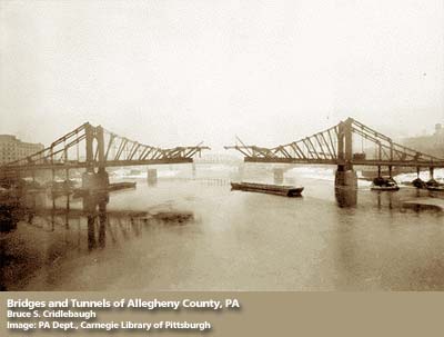
Three self-anchored suspension bridges in Pittsburgh | |
| Ancestor | Suspension bridge |
|---|---|
| Related | None |
| Descendant | None |
| Carries | Pedestrians, automobiles, trucks, light rail |
| Span range | Medium |
| Material | Steel rope, steel eyebar, concrete spar, post-tensioned concrete deck |
| Movable | No |
| Design effort | high |
| Falsework required | Sometimes |

A self-anchored suspension bridge is a suspension bridge in which the main cables attach to the ends of the deck, rather than to the ground via large anchorages. The design is well-suited for construction atop elevated piers, or in areas of unstable soils where anchorages would be difficult to construct.
- Difference between types of bridges
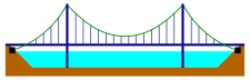 Suspension bridge with the main cables attached to the ground (black squares)
 Self-anchored suspension bridge; the main cables are attached to the end of the road deck
The load path of the self-anchored suspension (SAS) bridge converts vertical loads into tension forces in the main cables which are countered by compressive forces in the tower(s) and deck. The system balances forces internally without external anchorage requirements making it suitable for sites where large horizontal forces are difficult to anchor. This is similar to the method used in a tied-arch bridge where arch member compression is balanced by tension in the deck.
History
The self-anchored suspension bridge form originated in the mid-19th century, with a published description by Austrian engineer Josef Langer in 1859 and U.S. Patent No. 71,955 by American engineer Charles Bender in 1867. The form was applied to a handful of Rhine River crossings in Germany during the first half of the twentieth century.[1]
Examples
The Three Sisters Bridges of Pittsburgh are the earliest examples (1924–28) of this bridge type in the US; another well-known example is London's Chelsea Bridge (opened 1937). Previously the largest self-anchored suspension bridges are the Konohana Bridge in Japan and the Yeoungjong Grand Bridge in South Korea. Both of these bridges have a central span of 300 m. The SAS portion of the eastern span replacement of the San Francisco–Oakland Bay Bridge became self-supporting in November 2012, with a 385 m span (uniquely a half span as the bridge has only a single tower), and is currently the largest SAS bridge in the world.[2]
 Construction falsework on left; force schematic on right
 Asymmetrical single tower half span is a self-supporting SAS bridge -- part of eastern span of San Francisco-Oakland bay bridge
Construction method
Because the primary cables cannot be anchored until the bridge deck is completed, a self-anchored suspension bridge requires some falsework during construction. This falsework may take the form of compression struts (pictured here and in the above diagram) which hold up the main cables (or the parts of them which have already been constructed), allowing the ends of the span to be constructed first in the fashion of a cantilever bridge, or it may be in the form of underdeck falsework, as was employed in the Eastern span replacement of the San Francisco–Oakland Bay Bridge
Cable anchors

As in a traditional suspension bridge, the primary cable type may be multiple parallel independent cables as in the image at right of the Hutsonville Bridge (no longer extant), or eyebars, or a more conventional composite cable.
See also
References
- ↑ John A. Ochsendorf and David P. Billington, "Self-Anchored Suspension Bridges," ASCE Journal of Bridge Engineering, vol. 4, No. 3 (August 1999): 151-156.
- ↑ Cabanatuan, Michael (21 November 2012). "Bay Bridge span's 'Big Lift' complete". SF Gate. Retrieved 13 January 2013.
External links
- Yeonglong Grand Bridge A two tower, three span self-anchored bridge
| Types | 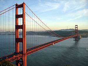 | |
|---|---|---|
| Lists | ||
| ||