Diving cylinder
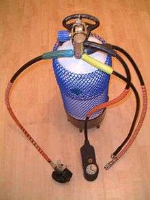
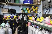
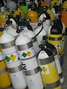 Diving cylinders to be filled at a diving air compressor station | |
| Other names | Scuba tank |
|---|---|
| Uses | Breathing gas supply for scuba or surface supplied divers |
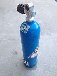
A diving cylinder, scuba tank or diving tank is a gas cylinder used to store and transport the high pressure breathing gas required by a scuba set. It may also be used for surface-supplied diving or as decompression gas or an emergency gas supply for surface supplied diving or scuba. Cylinders provide gas to the diver through the demand valve of a diving regulator or the breathing loop of a diving rebreather.
Diving cylinders are usually manufactured from aluminium or steel alloys, and are normally fitted with one of two common types of cylinder valve for filling and connection to the regulator. Other accessories such as manifolds, cylinder bands, protective nets and boots and carrying handles may be provided. Various configurations of harness may be used to carry the cylinder or cylinders while diving, depending on the application. Cylinders used for scuba typically have an internal volume (known as water capacity) of between 3 and 18 litres (0.11 and 0.64 cu ft) and a maximum working pressure rating from 184 to 300 bars (2,670 to 4,350 psi). Cylinders are also available in smaller sizes, such as 0.5, 1.5 and 2 litres, however these are often not used for breathing, instead being used for purposes such as inflation of surface marker buoys, drysuits and buoyancy compensators. Scuba divers may dive with a single cylinder, a pair of connected similar cylinders, or a main cylinder and a smaller "pony" cylinder, carried on the diver's back or clipped onto the harness at the sides. For some diving, more that two cylinders may be needed.
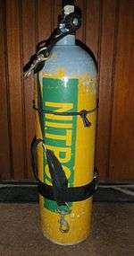
When pressurised, a cylinder carries an equivalent volume of free gas greater than its water capacity, because the gas is compressed up to several hundred times atmospheric pressure. The selection of an appropriate set of diving cylinders for a diving operation is based on the amount of gas required to safely complete the dive. Diving cylinders are most commonly filled with air, but because the main components of air can cause problems when breathed underwater at higher ambient pressure, divers may choose to breathe from cylinders filled with mixtures of gases other than air. A cylinder containing such mixtures needs to be labelled to indicate its contents for safety reasons. Many jurisdictions have regulations that govern the filling, recording of contents, and labelling for diving cylinders. Periodic inspection and testing of cylinders is often obligatory to ensure the safety of operators of filling stations. Pressurised diving cylinders are considered dangerous goods for commercial transportation, and regional and international rules for colouring and labelling may also apply.
Terminology
The term "diving cylinder" tends to be used by gas equipment engineers, manufacturers, support professionals, and divers speaking British English. "Scuba tank" or "diving tank" is more often used colloquially by non-professionals and native speakers of American English. The term "oxygen tank" is commonly used by non-divers when referring to diving cylinders; however, this is a misnomer. These cylinders typically contain (compressed atmospheric) breathing air, or an oxygen-enriched air mix. They rarely contain pure oxygen, except when used for rebreather diving, shallow decompression stops in technical diving or for in-water oxygen recompression therapy. Breathing pure oxygen at depths greater than 6 metres (20 ft), equivalent to a partial pressure of oxygen of 1.6 bars (1.6 atm), can result in oxygen toxicity, a highly dangerous condition that can trigger seizures and thus lead to drowning.[1]
Diving cylinders have also been referred to as bottles or flasks, usually with one of the epithets scuba, diving, or bailout. Cylinders may also be called aqualungs, a genericized trademark derived from the Aqua-lung equipment made by the Aqua Lung/La Spirotechnique company,[2] although that is more properly applied to an open circuit scuba set or open circuit diving regulator.
Diving cylinders may also be specified by their application, as in bailout cylinders, stage cylinders, deco cylinders, sidemount cylinders, pony cylinders, suit inflation cylinders, etc.
Parts of a cylinder
The functional diving cylinder consists of the pressure vessel and a cylinder valve:
The pressure vessel
The pressure vessel is a seamless cylinder normally made of cold-extruded aluminium or forged steel.[3] Filament wound composite cylinders are used in fire fighting breathing apparatus and oxygen first aid equipment because of their low weight, but are rarely used for diving, due to their high positive buoyancy. They are occasionally used when portability for accessing the dive site is critical, such as in cave diving.[4][5] Composite cylinders certified to ISO-11119-2 or ISO-11119-3 may only be used for underwater applications if they are manufactured in accordance with the requirements for underwater use and are marked "UW".[6]
Aluminium cylinders
An especially common cylinder provided at tropical dive resorts is the "aluminium-S80" which is an aluminium cylinder design with an internal volume of 0.39 cubic feet (11.0 L) rated to hold a nominal volume of 80 cubic feet (2,300 L) of atmospheric pressure gas at its rated working pressure of 3,000 pounds per square inch (207 bar).[7] Aluminium cylinders are also often used where divers carry many cylinders, such as in technical diving in water which is warm enough that the dive suit does not provide much buoyancy, because the greater buoyancy of aluminium cylinders reduces the amount of extra buoyancy the diver would need to achieve neutral buoyancy. They are also sometimes preferred when carried as "sidemount" or "sling" cylinders as the near neutral buoyancy allows them to hang comfortably along the sides of the diver's body, without disturbing trim, and they can be handed off to another diver or stage dropped with a minimal effect on buoyancy. Most aluminium cylinders are flat bottomed, allowing then to stand upright on a level surface, but some were manufactured with domed bottoms.
The aluminium alloys used for diving cylinders are 6061 and 6351. 6351 alloy is subject to sustained load cracking and cylinders manufactured of this alloy should be periodically eddy current tested according to national legislation and manufacturer's recommendations.[8][9] 6351 alloy has been superseded for new manufacture, but many old cylinders are still in service.
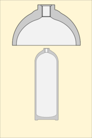
Manufacture
Aluminium cylinders are usually manufactured by cold extrusion of aluminium billets in a process which first presses the walls and base, then trims the top edge of the cylinder walls, followed by press forming the shoulder and neck. The final structural process is machining the neck outer surface, boring and cutting the neck threads and O-ring groove. The cylinder is then heat-treated, tested and stamped with the required permanent markings.[10] Aluminium diving cylinders commonly have flat bases, which allows them to stand upright on horizontal surfaces, and which are relatively thick to allow for rough treatment and considerable wear. This makes them heavier than they need to be for strength, but the extra weight at the base also helps keep the centre of gravity low which gives better balance in the water and reduces excess buoyancy.
-

Section of die with billet inserted
-

Cold extrusion process
-
Extrusion product before trimming
-
Section after closure of the top end
-
Section showing machined areas of the neck in detail
-
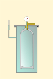
Hydrostatic test
Steel cylinders
In cold water diving, where a diver wearing a highly buoyant thermally insulating dive suit has a large excess of buoyancy, steel cylinders are often used because they are denser than aluminium cylinders. They also often have a lower mass than aluminium cylinders with the same gas capacity, due to considerably higher material strength, so the use of steel cylinders can result in both a lighter cylinder and less ballast required for the same gas capacity, a two way saving on overall dry weight carried by the diver.[11][12] Steel cylinders are more susceptible than aluminium to external corrosion, particularly in seawater, and may be galvanized or coated with corrosion barrier paints to resist corrosion damage. It is not difficult to monitor external corrosion, and repair the paint when damaged, and steel cylinders which are well maintained have a long service life, often longer than aluminium cylinders, as they are not susceptible to fatigue damage when filled within their safe working pressure limits.
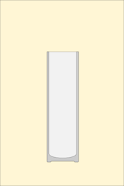
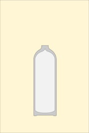
Steel cylinders are manufactured with domed (convex) and dished (concave) bottoms. The dished profile allows them to stand upright on a horizontal surface, and is the standard shape for industrial cylinders. The cylinders used for emergency gas supply on diving bells are often this shape, and commonly have a water capacity of about 50 litres ("J"). Domed bottoms give a larger volume for the same cylinder mass, and are the standard for scuba cylinders up to 18 litres water capacity, though some concave bottomed cylinders have been marketed for scuba.[13][14]
Manufacture
Steel alloys used for dive cylinder manufacture are authorised by the manufacturing standard. For example, the US standard DOT 3AA requires the use of open-hearth, basic oxygen, or electric steel of uniform quality. Approved alloys include 4130X, NE-8630, 9115, 9125, Carbon-boron and Intermediate manganese, with specified constituents, including manganese and carbon, and molybdenum, chromium, boron, nickel or zirconium.[15]
Steel cylinders may be manufactured from steel plate discs, which are cold drawn to a cylindrical cup form, in two or three stages, and generally have a domed base if intended for the scuba market, so they cannot stand up by themselves. After forming the base and side walls, the top of the cylinder is trimmed to length, heated and hot spun to form the shoulder and close the neck. This process thickens the material of the shoulder. The cylinder is heat-treated by quenching and tempering to provide the best strength and toughness. The cylinders are machined to provide the neck thread and o-ring seat (if applicable), then chemically cleaned or shot-blasted inside and out to remove mill-scale. After inspection and hydrostatic testing they are stamped with the required permanent markings, followed by external coating with a corrosion barrier paint or hot dip galvanising.[16]
Cylinder neck
The neck of the cylinder is internally threaded to fit a cylinder valve. There are several standards for neck threads, these include:
- Taper thread (17E),[17] with a 12% taper right hand thread, standard Whitworth 55° form with a pitch of 14 threads per inch (5.5 threads per cm) and pitch diameter at the top thread of the cylinder of 18.036 millimetres (0.71 in). These connections are sealed using thread tape and torqued to between 120 and 150 newton metres (89 and 111 lbf·ft) on steel cylinders, and between 75 and 140 N·m (55 and 103 lbf·ft) on aluminium cylinders.[18]
Parallel threads are made to several standards:
- M25x2 ISO parallel thread, which is sealed by an O-ring and torqued to 100 to 130 N·m (74 to 96 lbf·ft) on steel, and 95 to 130 N·m (70 to 96 lbf·ft) on aluminium cylinders;[18]
- M18x1.5 parallel thread, which is sealed by an O-ring, and torqued to 100 to 130 N·m (74 to 96 lbf·ft) on steel cylinders, and 85 to 100 N·m (63 to 74 lbf·ft) on aluminium cylinders;[18]
- 3/4"x14 BSP parallel thread,[19] which has a 55° Whitworth thread form, a pitch diameter of 25.279 millimetres (0.9952 in) and a pitch of 14 threads per inch (1.814 mm);
- 3/4"x14 NGS (NPSM) parallel thread, sealed by an O-ring, torqued to 40 to 50 N·m (30 to 37 lbf·ft) on aluminium cylinders,[20] which has a 60° thread form, a pitch diameter of 0.9820 to 0.9873 in (24.94 to 25.08 mm), and a pitch of 14 threads per inch (5.5 threads per cm);
- 3/4"x16 UNF, sealed by an O-ring, torqued to 40 to 50 N·m (30 to 37 lbf·ft) on aluminium cylinders.[20]
- 7/8"x14 UNF, sealed by an O-ring.[21]
The 3/4"NGS and 3/4"BSP are very similar, having the same pitch and a pitch diameter that only differs by about 0.2 mm (0.008 in), but they are not compatible, as the thread forms are different.
All parallel thread valves are sealed using an O-ring at top of the neck thread which seals in a chamfer or step in the cylinder neck and against the flange of the valve.
The shoulder of the cylinder carries stamp markings providing required information about the cylinder.[22]
-
Stamp markings on an American manufacture aluminum 40 cu ft 3000 psi cylinder
-
Stamp markings on an American manufacture aluminum 80 cu ft 3000 psi cylinder
-
Stamp markings on a British manufacture aluminium 12.2 litre 232 bar cylinder
-
Stamp markings on an Italian manufacture steel 7 litre 300 bar cylinder
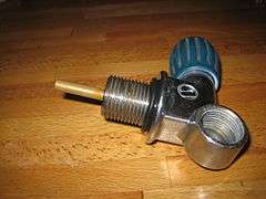
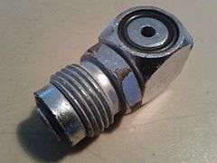
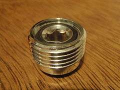
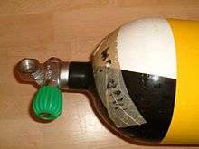
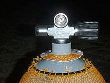
The cylinder valve
The purpose of the cylinder valve or pillar valve is to control gas flow to and from the pressure vessel and to provide a connection with the regulator or filling hose.[3] Cylinder valves are usually machined from brass and finished by a protective and decorative layer of chrome-plating.[23] A metal or plastic dip tube or valve snorkel screwed into the bottom of the valve extends into the cylinder to reduce the risk of liquid or particulate contaminants in the cylinder getting into the gas passages when the cylinder is inverted, and blocking or jamming the regulator. Some of these dip tubes have a plain opening, but some have an integral filter.[24][25]
Cylinder valves are classified by four basic aspects: The cylinder thread specification, the connection to the regulator, pressure rating, and other distinguishing features.
Cylinder thread variations
Cylinder threads may be in two basic configurations: Taper thread and parallel thread.[3] These thread specifications are detailed in a previous section. The valve thread specification must exactly match the neck thread specification of the cylinder. Improperly matched neck threads can fail under pressure and can have fatal consequences if someone is hit by the flying valve or cylinder.
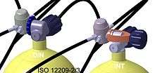
-
Draeger 300 bar taper thread DIN cylinder valve
-
A 232 bar DIN connection cylinder valve with M25x2 parallel thread cylinder connection
Connection to the regulator

A rubber o-ring forms a seal between the metal of the pillar valve and the metal of the diving regulator. Fluoroelastomer (e.g. viton) O-rings may be used with cylinders storing oxygen-rich gas mixtures to reduce the risk of fire.[26] There are two basic types of cylinder valve to regulator connection in general use for Scuba cylinders containing air:
- A-clamp or yoke connectors - the connection on the regulator surrounds the valve pillar and presses the output O-ring of the pillar valve against the input seat of the regulator. The connection is officially described as connection CGA 850 yoke.[27] The yoke is screwed down snug by hand (overtightening can make the yoke impossible to remove later without tools) and the seal is created by clamping the O-ring between the surfaces of the regulator and valve. When the valve is opened, cylinder pressure expands the O-ring against the outer surface of the O-ring groove in the valve. Insufficient clamping force may allow the pressure to extrude the O-ring between the valve and regulator faces, resulting in a leak. This type of connection is simple, cheap and very widely used worldwide. It has a maximum pressure rating of 232 bar and the weakest part of the seal, the O-ring, is not well protected from overpressurisation.[28]

- DIN screw thread connectors - the regulator screws into the cylinder valve trapping the O-ring securely between the sealing face of the valve and the O-ring groove in the regulator. These are more reliable than A-clamps because the O-ring is well protected, but many countries do not use DIN fittings widely on compressors, or cylinders which have DIN fittings, so a diver traveling abroad with a DIN system may need to take an adaptor, either for connecting the DIN regulator to a rented cylinder, or for connecting an A-clamp filler hose to a DIN cylinder valve.
There are also cylinder valves for scuba cylinders containing gases other than air:
- The new European Norm EN 144-3:2003 introduced a new type of valve, similar to existing 232 bar or 300 bar DIN valves, however, with a metric M26×2 fitting on both the cylinder and the regulator. These are intended to be used for breathing gas with oxygen content above that normally found in natural air in the Earth's atmosphere (i.e. 22–100%).[29] From August 2008, these were required in the European Union for all diving equipment used with nitrox or pure oxygen. The idea behind this new standard is to prevent a rich mixture being filled to a cylinder that is not oxygen clean. However even with use of the new system there still remains nothing except human procedural care to ensure that a cylinder with a new valve remains oxygen-clean[29] - which is exactly how the previous system worked.
- An M 24x2 male thread cylinder valve was supplied with some Dräger semi-closed circuit recreational rebreathers (Dräger Ray) for use with nitrox mixtures.[30] The regulator supplied with the rebreather had a compatible connection.
Pressure rating
Yoke valves are rated between 200 and 240 bar, and there does not appear to be any mechanical design detail preventing connection between any yoke fittings, though some older yoke clamps will not fit over the popular 232/240 bar combination DIN/yoke cylinder valve as the yoke is too narrow.
DIN valves are produced in 200 bar and 300 bar pressure ratings. The number of threads and the detail configuration of the connections is designed to prevent incompatible combinations of filler attachment or regulator attachment with the cylinder valve.[31]
- 232 bar DIN (5-thread, G5/8) Outlet/Connector #13 to DIN 477 part 1 - (technically they are specified for cylinders with 300 bar test pressure)[31]
- 300 bar DIN (7-thread, G5/8) Outlet/Connector #56 to DIN 477 part 5 - these are similar to 5-thread DIN fitting but are rated to 300 bar working pressures. (technically they are specified for cylinders with 450 bar test pressure).[31] The 300 bar pressures are common in European diving and in US cave diving.
Adaptors are available to allow connection of DIN regulators to yoke cylinder valves (A-clamp or yoke adaptor), and to connect yoke regulators to DIN cylinder valves.[31] (plug adaptors and block adaptors) Plug adaptors are rated for 232/240 bar, and can only be used with valves which are designed to accept them. Block adaptors are generally rated for 200 bar, and can be used with almost any 200 bar DIN valve.
-
A block adaptor screws into a DIN cylinder valve to allow connection of a yoke regulator
-
.jpg)
A yoke (A-clamp) to DIN adaptor allows connection of a DIN regulator to a Yoke cylinder valve
-
DIN plug adaptor for compatible cylinder valves
-
DIN valve with plug adaptor for yoke attachment fitted
Other distinguishing features
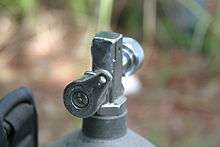
Plain valves
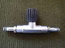
- The most commonly used cylinder valve type is the single outlet plain valve, sometimes known as a "K" valve,[14] which allows connection of a single regulator, and has no reserve function. It simply opens to allow gas flow, or closes to shut it off. Several configurations are used, with options of DIN or A-clamp connection, and vertical or transverse spindle arrangements. The valve is operated by turning a knob, usually rubber or plastic, which affords a comfortable grip. Several turns are required to fully open the valves. Some DIN valves are convertible to A-clamp by use of an insert which is screwed into the opening.
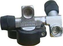
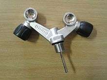
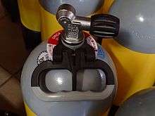
- Y and H cylinder valves have two outlets, each with its own valve, allowing two regulators to be connected to the cylinder.[4] If one regulator "freeflows", which is a common failure mode, or ices up, which can happen in water below about 5 °C, its valve can be closed and the cylinder breathed from the regulator connected to the other valve. The difference between an H-valve and a Y-valve is that the Y-valve body splits into two posts roughly 90° to each other and 45° from the vertical axis, looking like a Y, while an H-valve is usually assembled from a valve designed as part of a manifold system with an additional valve post connected to the manifold socket, with the valve posts parallel and vertical, which looks a bit like an H. Y-valves are also known as "slingshot valves" due to their appearance.[32]
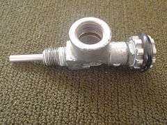
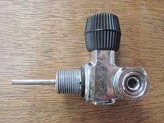
Reserve valves
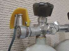
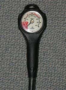
- Reserve lever or "J-valve". Until the 1970s, when submersible pressure gauges on regulators came into common use, diving cylinders often used a mechanical reserve mechanism to indicate to the diver that the cylinder was nearly empty. The gas supply was automatically cut-off by a spring loaded valve when the gas pressure reached the reserve pressure. To release the reserve, the diver pulled down on a rod that ran along the side of the cylinder and which activated a lever to open a bypass valve. The diver would then finish the dive before the reserve (typically 300 pounds per square inch (21 bar)) was consumed. On occasion, divers would inadvertently trigger the mechanism while donning gear or performing a movement underwater and, not realizing that the reserve had already been accessed, could find themselves out of air at depth with no warning whatsoever.[3][25] The J-valve got its name from being item "J" in one of the first scuba equipment manufacturer catalogs. The standard non-reserve yoke valve at the time was item "K", and is often still referred to as a K-valve.[14] J-valves are still occasionally used by professional divers in zero visibility, where the submersible pressure gauge (SPG) can not be read. While the recreational diving industry has largely discontinued support and sales of the J-valve, the US Department of Defense, the US Navy,[33] NOAA (the National Oceanographic and Atmospheric Administration) and OSHA (the national Occupational Health and Safety Administration) all still allow or recommend the use of J-valves as an alternative to a bailout cylinder or as an alternative to a submersible pressure gauge.[33] They are generally not available through recreational dive shops, but are still available from some manufacturers. They can be significantly more expensive than K-valves from the same manufacturer.
- Less common in the 1950s to 1970s was an R-valve which was equipped with a restriction that caused breathing to become difficult as the cylinder neared exhaustion, but that would allow less restricted breathing if the diver began to ascend and the ambient water pressure lessened, providing a larger pressure differential over the orifice. It was never particularly popular because, were it necessary for the diver to descend (as is often necessary in cave and wreck diving, breathing would become progressively more difficult as the diver went deeper, eventually becoming impossible until the diver could ascent to a low enough ambient pressure.[14]
Handed valves
Some cylinder valve models have axial spindles - in line with the cylinder axis, and are not handed. Standard side-spindle valves have the handwheel on the diver's right side when back-mounted. Side-spindle valves used with manifolds must be a handed pair - one with the handwheel to the right and the other with the handwheel to the left, but in all cases the valve is opened by turning the handwheel anticlockwise, and closed by turning it clockwise. This is the convention with almost all valves for all purposes. Left hand side-spindle valves are used by sidemount divers.[13][34]
Bursting disk
Some national standards require that the cylinder valve includes a bursting disk, a pressure relief device that will release the gas before the cylinder fails in the event of overpressurization.[3] If a bursting disk ruptures during a dive the entire contents of the cylinder will be lost in a very short time. The risk of this happening to a correctly rated disc, in good condition, on a correctly filled cylinder is very low.
Accessories
Additional components for convenience, protection or other functions, not directly required for the function as a pressure vessel.
Manifolds
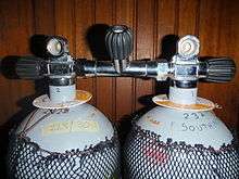
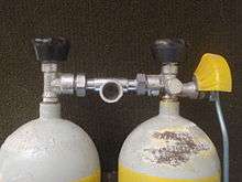
A cylinder manifold is a tube which connects two cylinders together so that the contents of both can be supplied to one or more regulators.[33][35] There are three commonly used configurations of manifold:
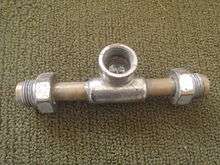
- The oldest type is a tube with a connector on each end which is attached to the cylinder valve outlet, and an outlet connection in the middle, to which the regulator is attached. A variation on this pattern includes a reserve valve at the outlet connector. The cylinders are isolated from the manifold when closed, and the manifold can be attached or disconnected while the cylinders are pressurised.[35]
- More recently, manifolds have become available which connect the cylinders on the cylinder side of the valve, leaving the outlet connection of the cylinder valve available for connection of a regulator. This means that the connection cannot be made or broken while the cylinders are pressurised, as there is no valve to isolate the manifold from the interior of the cylinder. This apparent inconvenience allows a regulator to be connected to each cylinder, and isolated from the internal pressure independently, which allows a malfunctioning regulator on one cylinder to be isolated while still allowing the regulator on the other cylinder access to all the gas in both cylinders.[35]
- These manifolds may be plain or may include an isolation valve in the manifold, which allows the contents of the cylinders to be isolated from each other. This allows the contents of one cylinder to be isolated and secured for the diver if a leak at the cylinder neck thread, manifold connection, or burst disk on the other cylinder causes its contents to be lost.[35]
A relatively uncommon manifold system is a connection which screws directly into the neck threads of both cylinders, and has a single valve to release gas to a connector for a regulator. These manifolds can include a reserve valve, either in the main valve or at one cylinder. This system is mainly of historical interest.[14]
Valve cage
Also known as a manifold cage or regulator cage, this is a structure which can be clamped to the neck or shoulder of the cylinder or manifolded cylinders to protect the valves and regulator first stages from impact and abrasion damage while in use[35] and from rolling the valve closed by friction of the handwheel against an overhead. A valve cage is often made of stainless steel,[35] and some designs can snag on obstructions.
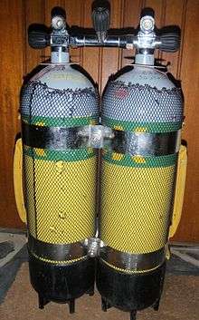
Cylinder bands
Cylinder bands are straps, usually of stainless steel, which are used to clamp two cylinders together as a twin set. The cylinders may be manifolded or independent. It is usual to use a cylinder band near the top of the cylinder, just below the shoulders, and one lower down. The conventional distance between centrelines for bolting to a backplate is 11 inches (280 mm).
Cylinder boot
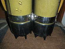
A cylinder boot is a hard rubber or plastic cover which fits over the base of a diving cylinder to protect the paint from abrasion and impact, to protect the surface the cylinder stands on from impact with the cylinder, and in the case of round bottomed cylinders, to allow the cylinder to stand upright on its base.[36] Some boots have flats moulded into the plastic to reduce the tendency of the cylinder to roll on a flat surface.[37] It is possible in some cases for water to be trapped between the boot and the cylinder, and if this is seawater and the paint under the boot is in poor condition, the surface of the cylinder may corrode in those areas.[36][38] This can usually be avoided by rinsing in fresh water after use and storing in a dry place. The added hydrodynamic drag caused by a cylinder boot is trivial in comparison with the overall drag of the diver, but some boot styles may present a slightly increased risk of snagging on the environment.
Cylinder net
A cylinder net is a tubular net which is stretched over a cylinder and tied on at top and bottom. The function is to protect the paintwork from scratching, and on booted cylinders it also helps drain the surface between the boot and cylinder, which reduces corrosion problems under the boot. Mesh size is usually about 6 millimetres (0.24 in). Some divers will not use boots or nets as they can snag more easily than a bare cylinder and constitute an entrapment hazard in some environments such as caves and the interior of wrecks. Occasionally sleeves made from other materials may be used to protect the cylinder.[37]
Cylinder handle
A cylinder handle may be fitted, usually clamped to the neck, to conveniently carry the cylinder. This can also increase the risk of snagging in an enclosed environment.
Dust caps and plugs
These are used to cover the cylinder valve orifice when the cylinder is not in use to prevent dust, water or other materials from contaminating the orifice. They can also help prevent the O-ring of a yoke type valve from falling out. The plug may be vented so that the leakage of gas from the cylinder does not pressurise the plug, making it difficult to remove.[39]
Cylinder pressure rating
The thickness of the cylinder walls is directly related to the working pressure, and this affects the buoyancy characteristics of the cylinder. A low-pressure cylinder will be more buoyant than a high-pressure cylinder with similar size and proportions of length to diameter and in the same alloy.
Working pressure
Scuba cylinders are technically all high-pressure gas containers, but within the industry in the US there are three nominal working pressure ratings (WP) in common use;[29]
- low pressure (2400 to 2640 psi — 165 to 182 bar),
- standard (3000 psi — 207 bar), and
- high pressure (3300 to 3500 psi — 227 to 241 bar).
US-made aluminum cylinders usually have a standard working pressure of 3,000 pounds per square inch (210 bar), and the compact aluminum range have a working pressure of 3,300 pounds per square inch (230 bar). Some steel cylinders manufactured to US standards are permitted to exceed the nominal working pressure by 10%, and this is indicated by a '+' symbol. This extra pressure allowance is dependent on the cylinder passing the appropriate higher standard periodical hydrostatic test.[24]
Those parts of the world using the metric system usually refer to the cylinder pressure directly in bar but would generally use "high pressure" to refer to a 300 bars (4,400 psi) working pressure cylinder, which can not be used with a yoke connector on the regulator. 232 bar is a very popular working pressure for scuba cylinders in both steel and aluminium.
Test pressure
Hydrostatic test pressure (TP) is specified by the manufacturing standard. This is usually 1.5 × working pressure, or in the USA, 1.67 × working pressure.
Developed pressure
Cylinder working pressure is specified at a reference temperature, usually 15 °C or 20 °C.[40] and cylinders also have a specified maximum safe working temperature, often 65 °C.[40] The actual pressure in the cylinder will vary with temperature, as described by the gas laws, but this is acceptable in terms of the standards provided that the developed pressure when corrected to the reference temperature does not exceed the specified working pressure stamped on the cylinder. This allows cylinders to be safely and legally filled to a pressure that is higher than the specified working pressure when the filling temperature is greater than the reference temperature, but not more than 65 °C, provided that the filling pressure does not exceed the developed pressure for that temperature, and cylinders filled according to this provision will be at the correct working pressure when cooled to the reference temperature.[40]
Pressure monitoring
The internal pressure of a diving cylinder is measured at several stages during use. It is checked before filling, monitored during filling and checked when filling is completed. This can all be done with the pressure gauge on the filling equipment.
Pressure is also generally monitored by the diver. Firstly as a check of contents before use, then during use to ensure that there is enough left at all times to allow a safe completion of the dive, and often after a dive for purposes of record keeping and personal consumption rate calculation.
The pressure is also monitored during hydrostatic testing to ensure that the test is done to the correct pressure.
Most diving cylinders do not have a dedicated pressure gauge, but this is a standard feature on most diving regulators, and a requirement on all filling facilities.
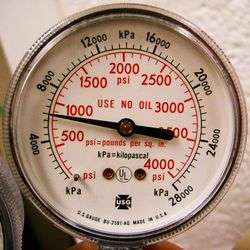
There are two widespread standards for pressure measurement of diving gas. In the USA and perhaps a few other places the pressure is measured in pounds per square inch (psi), and the rest of the world uses bar. Sometimes gauges may be calibrated in other metric units, such as kilopascal (kPa) or megapascal (MPa), or in atmospheres (atm, or ATA), particularly gauges not actually used underwater.
Cylinder capacity
There are two commonly used conventions for describing the capacity of a diving cylinder. One is based on the internal volume of the cylinder. The other is based on nominal volume of gas stored.
Internal volume
The internal volume is commonly quoted in most countries using the metric system. This information is required by ISO 13769 to be stamped on the cylinder shoulder. It can be measured easily by filling the cylinder with fresh water. This has resulted in the term 'water capacity', abbreviated as WC which is often stamp marked on the cylinder shoulder. It's almost always expressed as a volume in litres, but sometimes as mass of the water in kg. Fresh water has a density close to one kilogram per litre so the numerical values are effectively identical at one decimal place accuracy.[22]
Standard sizes by internal volume
These are representative examples, for a larger range, the on-line catalogues of the manufacturers such as Faber, Pressed Steel, Luxfer, and Catalina may be consulted. The applications are typical, but not exclusive.
- 22 litres: Available in steel, 200 and 232bar,[41]
- 20 litres: Available in steel, 200 and 232bar,[41]
- 18 litres: Available in steel, 200 and 232 bar,[41] used as single or twins for back gas.
- 16 litres: Available in steel, 200 and 232bar,[41] used as single or twins for back gas.
- 15 litres: Available in steel, 200 and 232 bar,[41] used as single or twins for back gas
- 12.2 litres: Available in steel 232, 300 bar[42] and aluminium 232 bar, used as single or twins for back gas
- 12 litres: Available in steel 200, 232, 300 bar,[42] and aluminium 232 bar, used as single or twins for back gas
- 11 litres: Available in aluminium, 200, 232 bar used as single, twins for back gas or sidemount
- 10.2 litres: Available in aluminium, 232 bar, used as single or twins for back gas
- 10 litres: Available in steel, 200, 232 and 300 bar,[43] used as single or twins for back gas, and for bailout
- 9.4 litres: Available in aluminium, 232 bar, used for back gas or as slings
- 8 litres: Available in steel, 200 bar, used for Semi-closed rebreathers
- 7 litres: Available in steel, 200, 232 and 300 bar,[44] and aluminium 232 bar, back gas as singles and twins, and as bailout cylinders. A popular size for SCBA
- 6 litres: Available in steel, 200, 232, 300 bar,[44] used for back gas as singles and twins, and as bailout cylinders. Also a popular size for SCBA
- 5.5 litres: Available in steel, 200 and 232 bar,[45]
- 5 litres: Available in steel, 200 bar,[45] used for rebreathers
- 4 litres: Available in steel, 200 bar,[45] used for rebreathers and pony cylinders
- 3 litres: Available in steel, 200 bar,[45] used for rebreathers and pony cylinders
- 2 litres: Available in steel, 200 bar,[45] used for rebreathers, pony cylinders, and suit inflation
- 1.5 litres: Available in steel, 200 and 232 bar,[45] used for suit inflation
- 0.5 litres: Available in steel and aluminium, 200 bar, used for buoyancy compensator and surface marker buoy inflation
Nominal volume of gas stored
The nominal volume of gas stored is commonly quoted as the cylinder capacity in the USA. It is a measure of the volume of gas that can be released from the full cylinder at atmospheric pressure.[33] Terms used for the capacity include 'free gas volume' or 'free gas equivalent'. It depends on the internal volume and the working pressure of a cylinder. If the working pressure is higher, the cylinder will store more gas for the same volume.
The nominal working pressure is not necessarily the same as the actual working pressure used. Some steel cylinders manufactured to US standards are permitted to exceed the nominal working pressure by 10% and this is indicated by a '+' symbol. This extra pressure allowance is dependent on the cylinder passing the appropriate periodical hydrostatic test and is not necessarily valid for US cylinders exported to countries with differing standards. The nominal gas content of these cylinders is based on the 10% higher pressure.[24]
For example, common Aluminum 80 (Al80) cylinder is an aluminum cylinder which has a nominal 'free gas' capacity of 80 cubic feet (2,300 L) when pressurized to 3,000 pounds per square inch (210 bar). It has an internal volume of 10.94 litres (0.386 cu ft).
Standard sizes by volume of gas stored
- Aluminum C100 ia a large (13.l l), high-pressure (3,300 pounds per square inch (228 bar)) cylinder. Heavy at 42.0 pounds (19.1 kg).[46]
- Aluminum S80 is probably the most ubiquitous cylinder, used by resorts in many parts of the world for back gas, but also popular as a sling cylinder for decompression gas, and as side-mount cylinder in fresh water, as it has nearly neutral buoyancy. These cylinders have an internal volume of approximately 11 litres (0.39 cu ft) and working pressure of 3,000 pounds per square inch (207 bar).[46] They are also sometimes used as manifolded twins for back mount, but in this application the diver needs more ballast weights than with most steel cylinders of equivalent capacity.
- Aluminium C80 is the high-pressure equivalent, with a water capacity of 10.3 l and working pressure 3,300 pounds per square inch (228 bar).[46]
- Aluminum S40 is a popular cylinder for side-mount and sling mount bailout and decompression gas for moderate depths, as it is small diameter and nearly neutral buoyancy, which makes it relatively unobtrusive for this mounting style. Internal volume is approximately 5.8 litres (0.20 cu ft) and working pressure 3,000 pounds per square inch (207 bar).[46]
- Aluminum S63 (9.0 l) 3,000 pounds per square inch (207 bar),[46] and steel HP65 (8.2 l) are smaller and lighter than the Al80, but have a lower capacity, and are suitable for smaller divers or shorter dives.
- Steel LP80 2,640 pounds per square inch (182 bar) and HP80 (10.1 l) at 3,442 pounds per square inch (237 bar) are both more compact and lighter than the Aluminium S80 and are both negatively buoyant, which reduces the amount of ballast weight required by the diver.[29]
- Steel HP119 (14.8 l), HP120 (15.3 l) and HP130 (16.0 l) cylinders provide larger amounts of gas for nitrox or technical diving.[47]
Applications and configurations of diving cylinders
Divers may carry one cylinder or multiples, depending on the requirements of the dive. Where diving takes place in low risk areas, where the diver may safely make a free ascent, or where a buddy is available to provide an alternative air supply in an emergency, recreational divers usually carry only one cylinder. Where diving risks are higher, for example where the visibility is low or when recreational divers do deeper or decompression diving, and particularly when diving under an overhead, divers routinely carry more than one gas source.
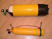
Diving cylinders may serve different purposes. One or two cylinders may be used as a primary breathing source which is intended to be breathed from for most of the dive. A smaller cylinder carried in addition to a larger cylinder is called a "pony bottle". A cylinder to be used purely as an independent safety reserve is called a "bailout bottle" or Emergency Gas Supply (EGS).[48] A pony bottle is commonly used as a bailout bottle, but this would depend on the time required to surface.
Divers doing technical diving often carry different gases, each in a separate cylinder, for each phase of the dive:[49]
- "travel gas" is used during the descent and ascent. It is typically air or nitrox with an oxygen content between 21% and 40%. Travel gas is needed when the bottom gas is hypoxic and therefore is unsafe to breathe in shallow water.
- "bottom gas" is only breathed at depth. It is typically a helium-based gas which is low in oxygen (below 21%) or hypoxic (below 17%).
- "deco gas" is used at the decompression stops and is generally one or more nitrox mixes with a high oxygen content, or pure oxygen, to accelerate decompression.
- a "stage" is a cylinder holding reserve, travel or deco gas. They are usually carried "side slung", clipped on either side of the diver to the harness of the backplate and wing or buoyancy compensator, rather than on the back, and may be left on the distance line to be picked up for use on return (stage dropped). Commonly divers use aluminium stage cylinders, particularly in fresh water, because they are nearly neutrally buoyant in water and can be removed underwater with less effect on the diver's overall buoyancy.
- "Suit inflation gas" may be taken from a breathing gas cylinder or may be supplied from a small independent cylinder.
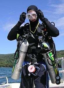
For safety, divers sometimes carry an additional independent scuba cylinder with its own regulator to mitigate out-of-air emergencies should the primary breathing gas supply fail. For much common recreational diving where a controlled emergency swimming ascent is acceptably safe, this extra equipment is not needed or used. This extra cylinder is known as a bail-out cylinder, and may be carried in several ways, and can be any size that can hold enough gas to get the diver safely back to the surface.[50]
Open-circuit scuba
For open-circuit scuba divers, there are several options for the combined cylinder and regulator system:
- Single cylinder consists of a single large cylinder, usually back mounted, with one first-stage regulator, and usually two second-stage regulators. This configuration is simple and cheap but it has only a single breathing gas supply: it has no redundancy in case of failure. If the cylinder or first-stage regulator fails, the diver is totally out of air and faces a life-threatening emergency. Recreational diver training agencies train divers to rely on a buddy to assist them in this situation. The skill of gas sharing is trained on most entry level scuba courses. This equipment configuration, although common with entry-level divers and used for most sport diving, is not recommended by training agencies for any dive where decompression stops are needed, or where there is an overhead environment (wreck diving, cave diving, or ice diving) as it provides no functional redundancy.
- Single cylinder with dual regulators consists of a single large back mounted cylinder, with two first-stage regulators, each with a second-stage regulator. This system is used for diving where cold water makes the risk of regulator freezing high and functional redundancy is required.[51] It is common in continental Europe, especially Germany. The advantage is that a regulator failure can be solved underwater to bring the dive to a controlled conclusion without buddy breathing or gas sharing.[51] However, it is hard to reach the valves, so there may be some reliance on the dive buddy to help close the valve of the free-flowing regulator quickly.
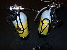
- Main cylinder plus a small independent cylinder: this configuration uses a larger, back mounted main cylinder along with an independent smaller cylinder, often called a "pony" or "bailout cylinder".[50] The diver has two independent systems, but the total 'breathing system' is now heavier, and more expensive to buy and maintain.
- The pony is typically a 2 to 5 litre cylinder. Its capacity determines the depth of dive and decompression duration for which it provides protection. Ponies may be fixed to the diver's buoyancy compensator (BC) or main cylinder behind the diver's back, or can be clipped to the harness at the diver's side or chest or carried as a sling cylinder. Ponies provide an accepted and reliable emergency gas supply but require that the diver is trained to use them.
- Another type of small independent air source is a hand-held cylinder filled with about 85 litres (3.0 cu ft) of free air with a diving regulator directly attached, such as the Spare Air.[52] This source provides only a few breaths of gas at depth and is most suitable as a shallow water bailout.
- Independent twin sets or independent doubles consists of two independent cylinders and two regulators, each with a submersible pressure gauge. This system is heavier, more expensive to buy and maintain and more expensive to fill than a single cylinder set. The diver must swap demand valves during the dive to preserve a sufficient reserve of gas in each cylinder. If this is not done, then if a cylinder should fail the diver may end up having an inadequate reserve. Independent twin sets do not work well with air-integrated computers as they usually only monitor one cylinder. The complexity of switching regulators periodically to ensure both cylinders are evenly used may be offset by the redundancy of two entirely separate breathing gas supplies. The cylinders may be mounted as a twin set on the diver's back, or alternatively can be carried in a sidemount configuration where penetration of wrecks or caves requires it, and where the cylinder valves are in easy reach.
- Plain manifolded twin sets, or manifolded doubles with a single regulator, consist of two back mounted cylinders with their pillar valves connected by a manifold but only one regulator is attached to the manifold. This makes it relatively simple and cheap but means there is no redundant functionality to the breathing system, only a double gas supply. This arrangement was fairly common in the early days of scuba when low-pressure cylinders were manifolded to provide a larger air supply than was possible from the available single cylinders. It is still in use for large capacity bailout sets for deep commercial diving.[53]
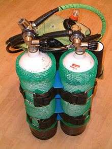
- Isolation manifolded twin sets or manifolded doubles with two regulators, consist of two back mounted cylinders with their pillar valves connected by a manifold, with a valve in the manifold that can be closed to isolate the two pillar valves. In the event of a problem with one cylinder the diver may close the isolator valve to preserve gas in the cylinder which has not failed. The advantages of this configuration include: a larger gas supply than from a single cylinder; automatic balancing of the gas supply between the two cylinders; thus, no requirement to constantly change regulators underwater during the dive; and in most failure situations, the diver may close a valve to a failed regulator or isolate a cylinder and may retain access to all the remaining gas in both the tanks. The disadvantages are that the manifold is another potential point of failure, and there is a danger of losing all gas from both cylinders if the isolation valve cannot be closed when a problem occurs. This configuration of cylinders is often used in technical diving.[49]
- Sling cylinders are a configuration of independent cylinders used for technical diving. They are independent cylinders with their own regulators and are carried clipped to the harness at the side of the diver. Their purpose may be to carry either stage, travel, decompression, or bailout gas while the back mounted cylinder(s) carry bottom gas. Stage cylinders carry gas to extend bottom time, travel gas is used to reach a depth where bottom gas may be safely used if it is hypoxic at the surface, and decompression gas is gas intended to be used during decompression to accelerate the elimination of inert gases. Bailout gas is an emergency supply intended to be used to surface if the main gas supply is lost.[49]
- Side-mount cylinders are cylinders clipped to the harness at the diver's sides which carry bottom gas when the diver does not carry back mount cylinders. They may be used in conjunction with other side mounted stage, travel and/or decompression cylinders where necessary. Skilled side-mount divers may carry as many as three cylinders on each side.[54] This configuration was developed for access through tight restrictions in caves. Side mounting is primarily used for technical diving, but is also sometimes used for recreational diving, when a single cylinder may be carried, complete with secondary second stage (octopus) regulator, in a configuration sometimes referred to as monkey diving.
Rebreathers
Diving cylinders are used in rebreather diving in two roles:
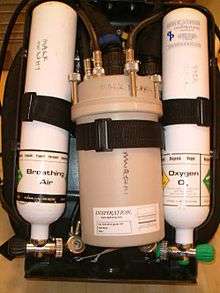
- As part of the rebreather itself. The rebreather must have at least one source of fresh gas stored in a cylinder; many have two and some have more cylinders. Due to the lower gas consumption of rebreathers, these cylinders typically are smaller than those used for equivalent open-circuit dives. Rebreathers may use internal cylinders, or may also be supplied from "off-board" cylinders, which are not directly plumbed into the rebreather, but connected to it by a flexible hose and coupling and usually carried side slung.
- Rebreather divers also often carry an external bailout system if the internal diluent cylinder is too small for safe use for bailout for the planned dive.[56] The bailout system is one or more independent breathing gas sources for use if the rebreather should fail:
- Open-circuit: One or more open circuit scuba sets. The number of open-circuit bailout sets, their capacity and the breathing gases they contain depend on the depth and decompression needs of the dive.[56] So on a deep, technical rebreather dive, the diver will need a bail out "bottom" gas and a bailout "decompression" gas(es). On such a dive, it is usually the capacity and duration of the bailout sets that limits the depth and duration of the dive - not the capacity of the rebreather.
- Closed-circuit: A second rebreather containing one or more independent diving cylinders for its gas supply. Using another rebreather as a bail-out is possible but uncommon.[56] Although the long duration of rebreathers seems compelling for bail-out, rebreathers are relatively bulky, complex, vulnerable to damage and require more time to start breathing from, than easy-to-use, instantly available, robust and reliable open-circuit equipment.
Surface supplied diver emergency gas supply
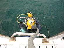
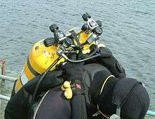
Surface supplied divers are usually required to carry an emergency gas supply sufficient to allow them to return to a place of safety if the main gas supply fails. The usual configuration is a back mounted single cylinder supported by the diver's safety harness, with first stage regulator connected by a low-pressure hose to a bailout block, which may be mounted on the side of the helmet or band-mask or on the harness to supply a lightweight full-face mask.[57][58][59] Where the capacity of a single cylinder in insufficient, plain manifolded twins or a rebreather may be used. For closed bell bounce and saturation dives the bailout set must be compact enough to allow the diver to pass through the bottom hatch of the bell. This sets a limit on the size of cylinders that can be used.[53][60]
Emergency gas supply on diving bells
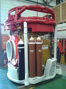
Diving bells are required to carry an on-board supply of breathing gas for use in emergencies.[61][62] The cylinders are mounted externally as there is insufficient space inside. They are fully immersed in the water during bell operations, and may be considered diving cylinders.
Suit inflation cylinders
Suit inflation gas may be carried in a small independent cylinder. Sometimes argon is used for superior insulation properties. This must be clearly labelled and may also need to be colour coded to avoid inadvertent use as a breathing gas, which could be fatal as argon is an asphyxiant.
Other uses of compressed gas cylinders in diving operations
Divers also use gas cylinders above water for storage of oxygen for first aid treatment of diving disorders and as part of storage "banks" for diving air compressor stations, gas blending, surface supplied breathing gas and gas supplies for decompression chambers and saturation systems. Similar cylinders are also used for many purposes not connected to diving. For these applications they are not diving cylinders and may not be subject to the same regulatory requirements as cylinders used underwater.
Gas calculations
It is necessary to know the approximate length of time that a diver can breathe from a given cylinder so that a safe dive profile can be planned.[63]
There are two parts to this problem: The cylinder and the diver.
The cylinder's capacity to store gas
Two features of the cylinder determine its gas carrying capacity:
- internal volume : this normally ranges between 3 litres and 18 litres for single cylinders.
- cylinder gas pressure : when filled this normally ranges between 200 and 300 bars (2,900 and 4,400 psi), but the actual value should be measured for a real situation, as the cylinder may not be full.
To calculate the quantity of gas:
- Volume of gas at atmospheric pressure = (cylinder volume) x (cylinder pressure) / (atmospheric pressure)
In those parts of the world using the metric system the calculation is relatively simple as atmospheric pressure may be approximated as 1 bar, So a 12-litre cylinder at 232 bar would hold almost 12 × 232 / 1 = 2,784 litres (98.3 cu ft) of air at atmospheric pressure (also known as free air).
In the US the capacity of a diving cylinder is specified directly in cubic feet of free air at the nominal working pressure, as the calculation from internal volume and working pressure is relatively tedious in imperial units. For examle, in the US and in many diving resorts in other countries, one might find aluminum cylinders of US manufacture with an internal capacity of 0.39 cubic feet (11 L) filled to a working pressure of 3,000 psi (210 bar); Taking atmospheric pressure as 14.7 psi, this gives 0.39 × 3000 / 14.7 = 80 ft³ These cylinders are described as "80 cubic foot cylinders", (the common "aluminum 80").
Up to about 200 bar the ideal gas law remains valid and the relationship between the pressure, size of the cylinder and gas contained in the cylinder is linear; at higher pressures there is proportionally less gas in the cylinder. A 3-litre cylinder filled to 300 bar will only carry contain 810 litres (29 cu ft) of atmospheric pressure gas and not the 900 litres (32 cu ft) expected from the ideal gas law.
Diver gas consumption
There are three main factors to consider:
- the rate at which the diver consumes gas, specified as surface air consumption (SAC) or respiratory minute volume (RMV) of the diver. In normal conditions this will be between 10 and 25 litres per minute (L/min) for divers who are not working hard. At times of extreme high work rate, breathing rates can rise to 95 litres per minute.[64] For International Marine Contractors Association (IMCA) commercial diving gas planning purposes, a working breathing rate of 40 litres per minute is used, whilst a figure of 50 litres per minute is used for emergencies.[59] RMV is controlled by blood CO2 levels, and is usually independent of oxygen partial pressures, so does not change with depth. The very large range of possible rates of gas consumption results in a significant uncertainty of how long the supply will last, and a conservative approach is required for safety where an immediate access to an alternative breathing gas source is not possible. Scuba divers are expected to monitor the remaining gas pressure sufficiently often that they are aware of how much is still available at all times during a dive.
- ambient pressure: the depth of the dive determines this. The ambient pressure at the surface is 1 bar (15 psi) at sea level. For every 10 metres (33 ft) in seawater the diver descends, the pressure increases by 1 bar (15 psi).[65] As a diver goes deeper, the breathing gas is delivered at a pressure equal to ambient water pressure, and the amount of gas used is proportional to the pressure. Thus, it requires twice as much mass of gas to fill the diver's lungs at 10 metres (33 ft) as it does at the surface, and three times as much at 20 metres (66 ft). The mass consumption of breathing gas by the diver is similarly affected.
- time at each depth. (usually approximated as time at each depth range)
To calculate the quantity of gas consumed:
- gas consumed = surface air consumption × time × ambient pressure
Metric examples:
- A diver with a RMV of 20 L/min at 30 msw (4 bar), will consume 20 x 4 x 1 = 80 L/min surface equivalent.
- A diver with a RMV of 40 L/min at 50 msw (6 bar) for 10 minutes will consume 40 x 6 x 10 = 2400 litres of free air – the full capacity of a 12 litre 200 bar cylinder.
Imperial examples:
- A diver with a SAC of 0.5 cfm (cubic feet per minute) at 100 fsw (4 ata) will consume 0.5 x 4 x 1 = 2 cfm surface equivalent.
- A diver with a SAC of 1 cfm at 231 fsw (8 ata) for 10 minutes will consume 1 x 8 x 10 = 80 ft3 of free air – the full capacity of an 80 ft3 cylinder
Keeping this in mind, it is not hard to see why technical divers who do long deep dives require multiple cylinders or rebreathers, and commercial divers normally use surface-supplied diving equipment, and only carry scuba as an emergency gas supply.
Breathing gas endurance
The amount of time that a diver can breathe from a cylinder is also known as air or gas endurance.
Absolute maximum breathing duration (BT) for a given depth can be calculated as
- BT = available air / rate of consumption[66]
which, using the ideal gas law, is
- BT = (available cylinder pressure × cylinder volume) / (rate of air consumption at surface) × (ambient pressure)[66]
This may be written as
- (1) BT = (PC-PA)*VC/(SAC*PA)
with
- BT = Breathing Time
- PC = Cylinder Pressure
- VC = Cylinder internal volume
- PA = Ambient Pressure
- SAC = Surface air consumption
in any consistent system of units.
Ambient pressure (PA) is the surrounding water pressure at a given depth and is made up of the sum of the hydrostatic pressure and the air pressure at the surface. It is calculated as
- (2) PA = D*g*ρ + atmospheric pressure[67]
with
- D = depth
- g = Standard gravity
- ρ = water density
in a consistent system of units
For metric units, this formula can be approximated by
- (3) PA = D/10 + 1
with depth in m and pressure in bar
Ambient pressure is deducted from cylinder pressure, as the quantity of air represented by PA can in practice not be used for breathing by the diver as it required to balance the ambient pressure of the water.
This formula neglects the cracking pressure required to open both first and second stages of the regulator, and pressure drop due to flow restrictions in the regulator, both of which are variable depending on the design and adjustment of the regulator, and flow rate, which depends on the breathing pattern of the diver and the gas in use. These factors are not easily estimated, so the calculated value for breathing duration will be more than the real value.
However, in normal diving usage, a reserve is always factored in. The reserve is a proportion of the cylinder pressure which a diver will not plan to use other than in case of emergency. The reserve may be a quarter or a third of the cylinder pressure or it may be a fixed pressure, common examples are 50 bar and 500 psi. The formula above is then modified to give the usable breathing duration as
- (4) BT = (PC-PR)*VC/(SAC*PA)
where PR is the reserve pres
For example, (using the first formula (1) for absolute maximum breathing time), a diver at a depth of 15 meters in water with an average density of 1020 kg/m³ (typical seawater), who breathes at a rate of 20 litres per minute, using a dive cylinder of 18 litres pressurized at 200 bars, can breathe for a period of 72 minutes before the cylinder pressure falls so low as to prevent inhalation. In some open circuit scuba systems this can happen quite suddenly, from a normal breath to the next abnormal breath, a breath which may not be fully drawn. (There is never any difficulty exhaling). The suddenness of this effect depends on the design of the regulator and the internal volume of the cylinder. In such circumstances there remains air under pressure in the cylinder, but the diver is unable to breathe it. Some of it can be breathed if the diver ascends, as the ambient pressure is reduced, and even without ascent, in some systems a bit of air from the cylinder is available to inflate buoyancy compensator devices (BCDs) even after it no longer has pressure enough to open the demand valve.
Using the same conditions and a reserve of 50 bar, the formula (4) for usable breathing time is follows:
- Ambient pressure = water pressure + atmospheric pressure = 15 msw/10 bar per msw + 1 = 2.5 bar
- Usable pressure = fill pressure - reserve pressure = 200 bar - 50 bar = 150 bar
- Usable air = usable pressure * cylinder capacity = 150 bar * 18 litres per bar = 2700 litres
- Rate of consumption = surface air consumption * ambient pressure = 20 litres per minute per bar * 2.5 bar = 50 litres/min
- Usable breathing time = 2700 litres / 50 litres per min = 54 minutes
This would give a dive time of 54 min at 15 m before reaching the reserve of 50 bar.
Reserves
It is strongly recommended by diver training organisations and codes of practice that a portion of the usable gas of the cylinder be held aside as a safety reserve. The reserve is designed to provide gas for longer than planned decompression stops or to provide time to resolve underwater emergencies.[66]
The size of the reserve depends upon the risks involved during the dive. A deep or decompression dive warrants a greater reserve than a shallow or a no stop dive. In recreational diving for example, it is recommended that the diver plans to surface with a reserve remaining in the cylinder of 500 psi, 50 bar or 25% of the initial capacity, depending of the teaching of the diver training organisation. This is because recreational divers practicing within "no-decompression" limits can normally make a direct ascent in an emergency. On technical dives where a direct ascent is either impossible (due to overhead obstructions) or dangerous (due to the requirement to make decompression stops), divers plan larger margins of safety. The simplest method uses the rule of thirds: one third of the gas supply is planned for the outward journey, one third is for the return journey and one third is a safety reserve.[68]
Some training agencies teach the concept of minimum gas, rock bottom gas management or critical pressures which allows a diver to calculate an acceptable reserve to get two divers to the surface in an emergency from any point in the planned dive profile.[49]
Professional divers may be required by legislation or industry codes of practice to carry sufficient reserve gas to enable them to reach a place of safety, such as the surface, or a diving bell, based on the planned dive profile.[58][59] This reserve gas is usually required to be carried as an independent emergency gas supply (EGS), also known as a bailout cylinder, set or bottle.[69] This usually also applies to professional divers using surface-supplied diving equipment.[58]
Weight of gas consumed
The density of air at sea level and 15 °C is approximately 1.225 kg/m3.[70] Most full-sized diving cylinders used for open circuit scuba hold more than 2 kilograms (4.4 lb) of air when full, and as the air is used, the buoyancy of the cylinder increases by the weight removed. The decrease in external volume of the cylinder due to reduction of internal pressure is relatively small, and can be ignored for practical purposes.
As an example, a 12-litre cylinder may be filled to 230 bar before a dive, and be breathed down to 30 bar before surfacing, using 2,400 litres or 2.4 m3 of free air. The mass of gas used during the dive will depend on the mixture - if air is assumed, it will be approximately 2.9 kilograms (6.4 lb).
The loss of the weight of the gas taken from the cylinder makes the cylinder and diver more buoyant. This can be a problem if the diver is unable to remain neutrally buoyant towards the end of the dive because most of the gas has been breathed from the cylinder. The buoyancy change due to gas usage from back mounted cylinders is easily compensated by carrying sufficient diving weights to provide neutral buoyancy with empty cylinders at the end of a dive, and using the buoyancy compensator to neutralise the excess weight until the gas has been used.
The change in buoyancy of a diving cylinder during the dive can be more problematic with side-mounted cylinders, and the actual buoyancy at any point during the dive is a consideration with any cylinder that may be separated from the diver for any reason. Cylinders which will be stage-dropped or handed off to another diver should not change the diver's buoyancy beyond what can be compensated using their buoyancy compensator. Cylinders with approximately neutral buoyancy when full generally require the least compensation when detached.
| Cylinder specification | Air capacity | Weight in air | Buoyancy in water | |||||
|---|---|---|---|---|---|---|---|---|
| Material | Volume (litre) |
Pressure (bar) |
Volume (litre) |
Weight (kg) |
Empty (kg) |
Full (kg) |
Empty (kg) |
Full (kg) |
| Steel | 12 | 200 | 2400 | 3.0 | 16.0 | 19.0 | -1.2 | -4.2 |
| 15 | 200 | 3000 | 3.8 | 20.0 | 23.8 | -1.4 | -5.2 | |
| 16 (XS 130) | 230 | 3680 | 4.4 | 19.5 | 23.9 | -0.9 | -5.3 | |
| 2x7 | 200 | 2800 | 3.4 | 19.5 | 23.0 | -2.2 | -5.6 | |
| 8 | 300 | 2400 | 2.9 | 13.0 | 16.0 | -3.6 | -6.5 | |
| 10 | 300 | 3000 | 3.6 | 17.0 | 20.8 | -4.2 | -7.8 | |
| 2x4 | 300 | 2400 | 2.9 | 15.0 | 18.0 | -4.1 | -7.0 | |
| 2x6 | 300 | 3600 | 4.4 | 21.0 | 25.6 | -5.2 | -9.6 | |
| Aluminium | 9 (AL 63) | 207 | 1863 | 2.3 | 12.2 | 13.5 | +1.8 | -0.5 |
| 11 (AL 80) | 207 | 2277 | 2.8 | 14.4 | 17.2 | +1.7 | -1.1 | |
| 13 (AL100) | 207 | 2584 | 3.2 | 17.1 | 20.3 | +1.4 | -1.8 | |
| Assumes 1 litre of air at atmospheric pressure and 15 °C weighs 1.225 g.[71] Cylinder, valve and manifold weights will vary depending on model, so actual values will value accordingly. | ||||||||
Filling cylinders
Diving cylinders are filled by attaching a high-pressure gas supply to the cylinder valve, opening the valve and allowing gas to flow into the cylinder until the desired pressure is reached, then closing the valves, venting the connection and disconnecting it. This process involves a risk of the cylinder or the filling equipment failing under pressure, both of which are hazardous to the operator, so procedures to control these risks are generally followed.
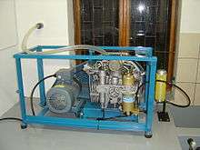
Filling from a compressor
Breathing air supply can come directly from a high-pressure breathing air compressor, from a high-pressure storage system, or from a combined storage system with compressor. Direct charging is energy intensive, and the charge rate will be limited by the available power source and capacity of the compressor. A large-volume bank of high-pressure storage cylinders allows faster charging or simultaneous charging of multiple cylinders, and allows for provision of more economical high-pressure air by recharging the storage banks from a low-power compressor, or using lower cost off-peak electrical power.
The quality of compressed breathing air for diving is usually specified by national or organisational standards, and the steps generally taken to assure the air quality include:[72]
- use of a compressor rated for breathing air,
- use of compressor lubricants rated for breathing air,
- filtration of intake air to remove particulate contamination,
- positioning of the compressor air intake in clean air clear of known sources of contaminants such as internal combustion exhaust fumes, sewer vents etc.
- removal of condensate from the compressed air by water separators. This may be done between stages on the compressor as well as after compression.
- filtration after compression to remove remaining water, oil, and other contaminants using specialized filter media such as desiccants, molecular sieve or activated carbon. Traces of carbon monoxide may be catalyzed to carbon dioxide by Hopcalite.
- periodical air quality tests,
- scheduled filter changes and maintenance of the compressor
Filling from high-pressure storage
Cylinders may also be filled directly from high-pressure storage systems by decanting, with or without pressure boosting to reach the desired charging pressure. Cascade filling may be used for efficiency when multiple storage cylinders are available. High-pressure storage is commonly used when blending nitrox, heliox and trimix diving gases, and for oxygen for rebreathers and decompression gas.[26]
Nitrox and trimix blending may include decanting the oxygen and/or helium, and topping up to working pressure using a compressor, after which the gas mixture must be analysed and the cylinder labeled with the gas composition.[26]
Temperature change during filling
Compression of ambient air causes a temperature rise of the gas, proportional to the pressure increase. Ambient air is typically compressed in stages, and the gas temperature rises during each stage. Intercoolers and water cooling heat exchangers can remove this heat between stages.
Charging an empty dive cylinder also causes a temperature rise as the gas inside the cylinder is compressed by the inflow of higher pressure gas, though this temperature rise may initially be tempered because compressed gas from a storage bank at room temperature decreases in temperature when it decreases in pressure, so at first the empty cylinder is charged with cold gas, but the temperature of the gas in the cylinder then increases to above ambient as the cylinder fills to the working pressure.
Excess heat can be removed by immersion of the cylinder in a cold water bath while filling. However, immersion for cooling can also increase the risk of water contaminating the valve orifice of a completely depressurized tank and being blown into the cylinder during filling.[73]
Cylinders may also be filled without water-bath cooling, and may be charged to above the nominal working pressure to the developed pressure appropriate to the temperature when filled. As the gas cools to ambient temperature, the pressure decreases, and will reach rated charging pressure at the rated temperature.[73]
Safety and legal issues
Legal constraints to filling scuba cylinders will vary by jurisdiction.
- In South Africa cylinders may be filled for commercial purposes by a person who is competent in the use of the filling equipment to be used, who knows the relevant sections of the applicable standards and regulations, and has written permission from the owner of the cylinder to fill it. The cylinder must be in test and suitable for the gas to be filled, and the cylinder may not be filled above the developed pressure for the temperature reached when it is filled. An external inspection of the cylinder must be made, and specified details of the cylinder and fill must be recorded. If the fill is of a gas other than air, the analysis of the completed fill must be recorded by the filler and signed by the customer.[40] If the residual pressure in a cylinder presented for filling does not produce a reasonably strong flow of gas from the valve when opened the filler may refuse to fill the cylinder unless an acceptable reason is given for it being empty, as there is no way for the filler to check if it has been contaminated.
Gas Purity and Testing
Diving cylinders should only be filled with suitably filtered air from diving air compressors or with other breathing gases using gas blending or decanting techniques.[72] In some jurisdictions, suppliers of breathing gases are required by legislation to periodically test the quality of compressed air produced by their equipment and to display the test results for public information.[40] The standards for industrial gas purity and filling equipment and procedures may allow some contaminants at levels unsafe for breathing,[36] and their use in breathing gas mixtures at high pressure could be harmful or fatal.
Handling of specialty gases
Special precautions need to be taken with gases other than air:
- oxygen in high concentrations is a major cause of fire and rust.[26]
- oxygen should be very carefully transferred from one cylinder to another and only ever stored in containers that are cleaned and labeled for oxygen use.[26]
- gas mixtures containing proportions of oxygen other than 21% could be extremely dangerous to divers who are unaware of the proportion of oxygen in them. All cylinders should be labeled with their composition.
- cylinders containing a high oxygen content must be cleaned for the use of oxygen and their valves lubricated only with oxygen service grease to reduce the chance of combustion.[26]
Specialty mixed gas charging will almost always involve supply cylinders of high purity gas sourced from an industrial gas supplier.
Gas Contamination
Contaminated air at depth can be fatal. Common contaminants are: carbon monoxide - a by-product of combustion, carbon dioxide - a product of metabolism, and oil and lubricants from the compressor.[72]
Keeping the cylinder slightly pressurized at all times during storage and transportation reduces the possibility of inadvertently contaminating the inside of the cylinder with corrosive agents, such as sea water, or toxic material, such as oils, poisonous gases, fungi or bacteria.[38] A normal dive will end with some pressure remaining in the cylinder; if an emergency ascent has been made due to an out-of-gas incident, the cylinder will normally still contain some pressure and unless the cylinder had been submerged deeper than where the last gas was used it is not possible for water to get in during the dive.
Contamination by water during filling may be due to two causes. Inadequate filtration and drying of the compressed air can introduce small quantities of fresh water condensate, or an emulsion of water and compressor lubricant, and failing to clear the cylinder valve orifice of water which may have dripped from wet dive gear, which can allow contamination by fresh or seawater. Both cause corrosion, but seawater contamination can cause a cylinder to corrode rapidly to the extent that it may be unsafe or condemned after even a fairly short period. This problem is exacerbated in hot climates, where chemical reactions are faster, and is more prevalent where filling staff are badly trained or overworked.[74]
Catastrophic failures during filling
The blast caused by a sudden release of the gas pressure inside a diving cylinder makes them very dangerous if mismanaged. The greatest risk of explosion exists while filling,[75] but cylinders have also been known to burst when overheated. The cause of failure can range from reduced wall thickness or deep pitting due to internal corrosion, neck thread failure due to incompatible valve threads, or cracking due to fatigue, sustained high stresses, or overheating effects in aluminum.[38][76] Tank bursting due to overpressure may be prevented by a pressure-relief burst disc fitted to the cylinder valve, which bursts if the cylinder is overpressurised and vents air at a rapid controlled rate to prevent catastrophic tank failure. Accidental rupture of the burst disc can also occur during filling, due to corrosive weakening or stress from repeated pressurization cycles, but is remedied by replacement of the disc. Bursting discs are not required in all jurisdictions.
Other failure modes that are a hazard while filling include valve thread failure, which can cause the valve to blow out of the cylinder neck, and filling whip failure.
Periodic inspection and testing of diving cylinders
Most countries require diving cylinders to be checked on a regular basis. This usually consists of an internal visual inspection and a hydrostatic test. The inspection and testing requirements for scuba cylinders may be very different from the requirements for other compressed gas containers due to the more corrosive environment.[40]
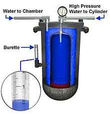
A hydrostatic test involves pressurising the cylinder to its test pressure (usually 5/3 or 3/2 of the working pressure) and measuring its volume before and after the test. A permanent increase in volume above the tolerated level means the cylinder fails the test and must be permanently removed from service.[3]
An inspection includes external and internal inspection for damage, corrosion, and correct colour and markings. The failure criteria vary according to the published standards of the relevant authority, but may include inspection for bulges, overheating, dents, gouges, electrical arc scars, pitting, line corrosion, general corrosion, cracks, thread damage, defacing of permanent markings, and colour coding.[3][40]
When a cylinder is manufactured, its specification, including manufacturer, working pressure, test pressure, date of manufacture, capacity and weight are stamped on the cylinder.[22] After a cylinder passes the test, the test date, (or the test expiry date in some countries such as Germany), is punched into the shoulder of the cylinder for easy verification at fill time. [note 1] The international standard for the stamp format is ISO 13769, Gas cylinders - Stamp marking.[22]
Filling station operators may be required to check these details before filling the cylinder and may refuse to fill non-standard or out-of-test cylinders. [note 2]
Intervals between inspections and tests
A cylinder is due to be inspected and tested at the first time it is to be filled after the expiry of the interval as specified by the United Nations Recommendations on the Transport of Dangerous Goods, Model Regulations, or as specified by national or international standards applicable in the region of use.[77][78]
- In the United States, an annual visual inspection is not required by the USA DOT, though they do require a hydrostatic test every five years. The visual inspection requirement is a diving industry standard based on observations made during a review by the National Underwater Accident Data Center.[79]
- In European Union countries a visual inspection is required every 2.5 years, and a hydrostatic test every five years.[80][81]
- In Norway a hydrostatic test (including a visual inspection) is required 3 years after production date, then every 2 years.
- Legislation in Australia requires that cylinders are hydrostatically tested every twelve months.[82]
- In South Africa a hydrostatic test is required every 4 years, and visual inspection every year. Eddy current testing of neck threads must be done according to the manufacturer's recommendations.[40]
Procedures for periodic inspections and tests
If a cylinder passes the listed procedures, but the condition remains doubtful, further tests can be applied to ensure that the cylinder id fit for use. Cylinders that fail the tests or inspection and cannot be fixed should be rendered unserviceable after notifying the owner of the reason for failure.[83][84]
Before starting work the cylinder must be identified from the labelling and permanent stamp markings, and the ownership and contents verified,[85][86] and the valve must be removed after depressurising and verifying that the valve is open. Cylinders containing breathing gases do not need special precautions for discharge except that high oxygen fraction gases should not be released in an enclosed space because of the fire hazard. [87][88] Before inspection the cylinder must be clean and free of loose coatings, corrosion products and other materials which may obscure the surface.[89]
The cylinder is inspected externally for dents, cracks, gouges, cuts, bulges, laminations and excessive wear, heat damage, torch or electric arc burns, corrosion damage, illegible, incorrect or unauthorised permanent stamp markings, and unauthorised additions or modifications.[90][91] Unless the cylinder walls are examined by ultrasonic methods, the interior must be visually inspected using sufficient illumination to identify any damage and defects, particularly corrosion. If the inner surface is not clearly visible it should first be cleaned by an approved method which does not remove a significant amount of wall material.[92][93] When there is uncertainty whether a defect found during visual inspection meets the rejection criteria, additional tests may be applied, such as ultrasonic measurement of pitting wall thickness, or weight checks to establish total weight lost to corrosion.[94]
While the valve is off, the threads of cylinder and valve are checked to identify the thread type and condition. The threads of cylinder and valve must be of matching thread specification, clean and full form, undamaged and free of cracks, burrs and other imperfections.[95][96] Ultrasonic inspection may be substituted for the pressure test, which is usually a hydrostatic test and may be either a proof test or a volumetric expansion test, depending on the cylinder design specification. Test pressure is specified in the stamp markings of the cylinder.[97][98] Valves that are to be reused are inspected and maintained to ensure they remain fit for service.[99][100] Before fitting the valve the thread type must be checked to ensure that a valve with matching thread specification is fitted.[101]
After the tests have been satisfactorily completed, a cylinder passing the test will be marked accordingly. Stamp marking will include the registered mark of the inspection facility and the date of testing (month and year).[102][103] Records of a periodic inspection and test are made by the test station and kept available for inspection. These include:[104][105] If a cylinder fails inspection or testing and cannot be recovered, the owner must be notified before making the empty cylinder unserviceable.[106]
Safety
Before any cylinder is filled, verification of inspection and testing dates and a visual examination for external damage and corrosion are required by law in some jurisdictions,[40] and are prudent even if not legally required at other places. Inspection dates can be checked by looking at the visual inspection label and the hydrostatic test date is stamped on the shoulder of the cylinder.[40]
Before use the user should verify the contents of the cylinder and check the function of the cylinder valve. This is usually done with a regulator connected to control the flow. Pressure and gas mixture are critical information for the diver, and the valve should open freely without sticking or leaking from the spindle seals. Breathing gas bled from a cylinder may be checked for smell. If the gas does not smell right it should not be used. Breathing gas should be almost free of smell, though a very slight aroma of the compressor lubricant is fairly common. No smell of combustion products or volatile hydrocarbons should be discernible.[36] Failure to recognize that the gas was not on or that cylinder was empty by divers conducting a pre-dive evaluation has been noted.[107]
A neatly assembled setup, with regulators, gauges, and delicate computers stowed inside the BCD, or clipped where they will not be walked on, and stowed under the boat bench or secured to a rack, is the practice of a competent diver.
As the scuba set is a life support system, no unauthorised person should touch a diver's assembled scuba gear, even to move it, without their knowledge and approval.
Full cylinders should not be exposed to temperatures above 65 °C[40] and cylinders should not be filled to pressures greater than the developed pressure appropriate to the certified working pressure of the cylinder.[40]
Cylinders should be clearly labelled with their current contents. A generic "Nitrox" or "Trimix" label will alert the user that the contents may not be air, and must be analysed before use. In some parts of the world a label is required specifically indicating that the contents are air, and in other places a colour code without additional labels indicates by default that the contents are air.[40]
In a fire, the pressure in a gas cylinder rises in direct proportion to its absolute temperature. If the internal pressure exceeds the mechanical limitations of the cylinder and there are no means to safely vent the pressurized gas to the atmosphere, the vessel will fail mechanically. If the vessel contents are ignitable or a contaminant is present this event may result in an explosion.[108]
Accidents
The major diving accident and fatality research studies that have been conducted globally including work by the Divers Alert Network, the Diving Incident Monitoring Study, and Project Stickybeak have each identified cases where the mortality was associated with the diving cylinder.[109][110]
Some recorded accidents associated with diving cylinders:[76]
- Valve ejected due to mix up with valve threads 3/4"NPSM and 3/4"BSP(F) caused damage to a dive shop compressor room.
- Dive Instructor leg nearly amputated by ejected valve while attempting to remove valve from pressurised cylinder.
- Valve ejected during filling due to thread failure, sank dive boat. Bursting disks in cylinder valves replaced by solid bolts.
- Filling hose failure severely injured operator when hose hit his face. Wound exposed jaw bone. 14 stitches to close the wound.
Cases of lateral epicondylitis have been reported caused by the handling of diving cylinders.[111]
Handling
Cylinders should not be left standing unattended unless secured[40] so that they can not fall in reasonably foreseeable circumstances as an impact could damage the cylinder valve mechanism, and conceivably fracture the valve at the neck threads. This is more likely with taper thread valves, and when it happens most of the energy of the compressed gas is released within a second, and can accelerate the cylinder to speeds which can cause severe injury or damage to the surroundings.[36][112]
Long term storage
Breathing quality gases do not normally deteriorate during storage in steel or aluminium cylinders. Provided there is insufficient water content to promote internal corrosion, the stored gas will remain unchanged for years if stored at temperatures within the allowed working range for the cylinder, usually below 65 °C. If there is any doubt, a check of oxygen fraction will indicate whether the gas has changed (the other components are inert). Any unusual smells would be an indication that the cylinder or gas was contaminated at the time of filling. However some authorities recommend releasing most of the contents and storing cylinders with a small positive pressure.[113]
Transportation
Diving cylinders are classified by the UN as dangerous goods for transportation purposes (US: Hazardous materials). Selecting the Proper Shipping Name (well known by the abbreviation PSN) is a way to help ensure that the dangerous goods offered for transport accurately represent the hazards.[114]
IATA Dangerous Goods Regulations (DGR) 55th Edition defines the Proper Shipping Name as "the name to be used to describe a particular article or substance in all shipping documents and notifications and, where appropriate, on packagings".[114]
The International Maritime Dangerous Goods Code (IMDG Code) defines the Proper Shipping Name as "that portion of the entry most accurately describing the goods in the Dangerous Goods List which is shown in upper-case characters (plus any letters which form an integral part of the name)."[114]
| Hazardous materials descriptions and proper shipping names (PSN)[115][116][117] |
Hazard class or division |
Identification numbers |
Label codes | Quantity limitations |
|---|---|---|---|---|
| Air, compressed | 2.2 | UN1002 | 2.2 | Passenger aircraft/rail: 75 kg Cargo aircraft only: 150 kg |
| Argon, compressed | 2.2 | UN1006 | 2.2 | |
| Helium, compressed | 2.2 | UN1046 | 2.2 | |
| Nitrogen, compressed | 2.2 | UN1066 | 2.2 | |
| Oxygen, compressed | 2.2 | UN1072 | 2.2, 5.1 | |
| Compressed gas N.O.S. (not otherwise specified) e.g. normoxic and hypoxic Heliox and Trimix |
2.2 | UN1956 | 2.2 | |
| Compressed gas, oxidising, N.O.S e.g. Nitrox |
2.2 | UN3156 | 2.2, 5.1 | |
International air
International Civil Aviation Organisation (ICAO) Technical Instructions for the Safe Transport of Dangerous Goods by Air states that provided that pressure in diving cylinders is less than 200 kilopascals (2 bar; 29 psi), these can be carried as checked in or carry-on baggage. It maybe necessary to empty the cylinder to verify this. Once emptied, the cylinder valve should be closed to prevent moisture entering the cylinder. Security restrictions implemented by individual countries may further limit or forbid the carriage of some items permitted by ICAO, and airlines and security screening agencies have the right to refuse the carriage of certain items.[118]
Europe
Since 1996 the carriage of dangerous goods legislation of the UK has been harmonized with that of Europe.[119]
Road transport
The 2009 (amended 2011) UK Carriage of Dangerous Goods and Use of Transportable Pressure Equipment Regulations (CDG Regulations) implement the European Agreement Concerning the International Carriage of Dangerous Goods by Road (ADR). Dangerous goods to be carried internationally in road vehicles must comply with standards for the packaging and labelling of the dangerous goods, and appropriate construction and operating standards for the vehicles and crew.[116][119]
The regulations cover transportation of gas cylinders in a vehicle in a commercial environment. Transportation of pressurised diving gas cylinders with a combined water capacity of less than 1000 litres on a vehicle for personal use is exempt from ADR.[116][119][120]
Transport of gas cylinders in a vehicle, for commercial purposes, must follow basic legal safety requirements and, unless specifically exempted, must comply with ADR. The driver of the vehicle is legally responsible for the safety of the vehicle and any load being carried, and insurance for the vehicle should include cover for the carriage of dangerous goods.[116][119]
Diving gases, including compressed air, oxygen, nitrox, heliox, trimix, helium and argon, are non-toxic, non flammable, and may be oxidizer or asphyxiant, and are rated in Transport category 3.[119] The threshold quantity for these gases is 1000 litres combined water capacity of the cylinders. Pressure must be within the rated working pressure of the cylinder. Empty air cylinders at atmospheric pressure are rated in Transport category 4, and there is no threshold quantity.[116][119]
Commercial loads below the 1000 litres threshold level are exempt from some of the requirements of ADR, but must comply with basic legal and safety requirements, including:[119]
- Driver training
- Cylinders should be transported in open vehicles, open containers or trailers, with a gas-tight bulkhead separating driver from load. If cylinders must be carried inside a vehicle it must be well ventilated.
- Ventilation. Where gas cylinders are carried inside a vehicle, in the same space as people, the windows should be kept open to allow air to circulate.
- Cylinders must be secured so that they cannot move during transport. They shall not project beyond the sides or ends of the vehicle. It is recommended that cylinders are transported vertically, secured in an appropriate pallet.
- Cylinder valves must be closed whilst in transit and checked that there are no leaks. Where applicable, protective valve caps and covers should be fitted to cylinders before transporting. Cylinders should not be transported with equipment attached to the valve outlet (regulators, hoses etc.).
- A fire extinguisher is required on the vehicle.
- Gas cylinders may only be transported if they are in-date for periodic inspection and test, except they may be transported when out of date for inspection, testing or disposal.
- Cylinders should be kept cool (at ambient temperatures) and not stowed in places where they will be exposed to sources of excessive heat.
- Product identification labels attached to cylinders to identify the contents and provide safety advice must not be removed or defaced.
- It is not necessary to mark and label the vehicle if carrying dangerous goods below the threshold level. The use of hazard labels can assist the emergency services, and they may be displayed, but all hazard labels must be removed when the relevant dangerous goods are not being transported.
- When the journey is complete the gas cylinders should be immediately unloaded from the vehicle.
All loads above the threshold must comply with the full requirements of ADR.[116][119]
USA
Transportation of hazardous materials for commercial purposes[121] in the USA is regulated by Code of Federal Regulations Title 49 - Transportation, (abbreviated 49 CFR).[122] A cylinder containing 200 kPa (29.0 psig/43.8 psia) or greater at 20 °C (68 °F) of non-flammable, nonpoisonous compressed gas, and being transported for commercial purposes is classified as HAZMAT (hazardous materials) in terms of 49 CFR 173.115(b) (1).[123] Cylinders manufactured to DOT standards or special permits (exemptions)issued by the Pipeline and Hazardous Materials Safety Administration and filled to the authorized working pressure are legal for commercial transport in the USA under the provisions and conditions of the regulations.[122][124] Cylinders manufactured outside the USA may be transported under a special permit, and these have been issued for solid metal and composite cylinders with working pressures of up to 300 bar (4400 psi) by several manufacturers.
Surface transport
Commercial transportation of breathing gas cylinders with a combined weight of more than 1000 pounds may only be done by a commercial HAZMAT transportation company. Transport of cylinders with a combined weight of less than 1000 pounds requires a manifest, the cylinders must have been tested and inspected to federal standards, and the contents marked on each cylinder. Transportation must be done in a safe manner, with the cylinders restrained from movement. No special licence is required. DOT regulations require content labels for all cylinders under the regulations, but according to PSI, labelling of breathing air will not be enforced. Oxygen or non-air oxidizing (O2 ≥ 23.5% ) mixtures must be labelled. Private (non-commercial) transport of scuba cylinders is not covered by this regulation.[125]
Air transport
Empty scuba tanks or scuba tanks pressurized at less than 200 kPa are not restricted as hazardous materials.[126] Scuba cylinders are only allowed in checked baggage or as a carry-on if the cylinder valve is completely disconnected from the cylinder and the cylinder has an open end to allow for a visual inspection inside.[127]
Gas cylinder colour-coding and labeling
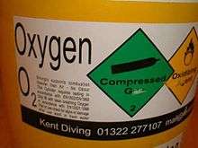
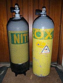
Worldwide
The colours permitted for diving cylinders vary considerably by region, and to some extent by the gas mixture contained.
In some parts of the world there is no legislation controlling the colour of diving cylinders. In other regions the colour of cylinders used for commercial diving, or for all underwater diving may be specified by national standards.[40]
In many recreational diving settings where air and nitrox are the widely used gases, nitrox cylinders are identified with a green stripe on yellow background. Aluminium diving cylinders may be painted or anodized and when anodized may be coloured or left in their natural silver. Steel diving cylinders are usually painted, to reduce corrosion, often yellow or white to increase visibility. In some industrial cylinder identification colour tables, yellow shoulders means chlorine and more generally within Europe it refers to cylinders with toxic and/or corrosive contents; but this is of no significance in scuba since gas fittings would not be compatible.
Cylinders that are used for partial pressure gas blending with pure oxygen may also be required to display an "oxygen service certificate" label indicating they have been prepared for use with high partial pressures and gas fractions of oxygen.
European Union
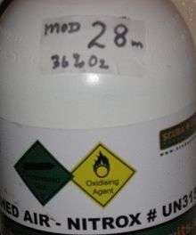
In the European Union gas cylinders may be colour-coded according to EN 1098-3. In the UK this standard is optional. The "shoulder" is the domed top of the cylinder between the parallel section and the pillar valve. For mixed gases, the colours can be either bands or "quarters".[128]
- Air has either a white (RAL 9010) top and black (RAL 9005) band on the shoulder, or white (RAL 9010) and black (RAL 9005) "quartered" shoulders.
- Heliox has either a white (RAL 9010) top and brown (RAL 8008) band on the shoulder, or white (RAL 9010) and brown (RAL 8008) "quartered" shoulders.
- Nitrox, like Air, has either a white (RAL 9010) top and black (RAL 9005) band on the shoulder, or white (RAL 9010) and black (RAL 9005) "quartered" shoulders.
- Pure oxygen has a white shoulder (RAL 9010).
- Pure helium has a brown shoulder (RAL 9008).
- Trimix has a white, black and brown segmented shoulder.
These breathing gas cylinders must also be labeled with their contents. The label should state the type of breathing gas contained by the cylinder.[128]
Offshore
Breathing gas containers for offshore use may be coded and marked according to IMCA D043.[128][129]
IMCA colour coding for individual cylinders allows the body of the cylinder to be any colour that is not likely to cause misinterpretation of the hazard identified by the colour code of the shoulder.
| Gas | Symbol | Typical shoulder colours | Cylinder shoulder | Quad upper frame/ frame valve end |
|---|---|---|---|---|
| Calibration gases | as appropriate | 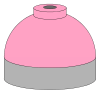 |
Pink | Pink |
| Carbon dioxide | CO2 | 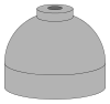 |
Grey | Grey |
| Helium | He | 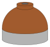 |
Brown | Brown |
| Medical oxygen | O2 | 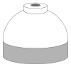 |
White | White |
| Nitrogen | N2 |  |
Black | Black |
| Oxygen and helium mixtures (Heliox) |
O2/He |   |
Brown and white quarters or bands |
Brown and white short (8 inches (20 cm)) alternating bands |
| Oxygen, helium and nitrogen mixtures (Trimix) |
O2/He/N2 |   |
Black, white and brown quarters or bands |
Black, white and brown short (8 inches (20 cm)) alternating bands |
| Oxygen and nitrogen mixtures (Nitrox) including air |
N2/O2 |   |
Black and white quarters or bands |
Black and white short (8 inches (20 cm)) alternating bands |
South Africa
Scuba cylinders are required to comply with the colours and markings specified in SANS 10019:2006.[40]
- Cylinder colour is Golden yellow with a French grey shoulder.
- Cylinders containing gases other than air or medical oxygen must have a transparent adhesive label stuck on below the shoulder with the word NITROX or TRIMIX in green and the composition of the gas listed.
- Cylinders containing medical oxygen must be black with a white shoulder.
Notes
References
- ↑ NOAA Diving Manual 2001, Section 3.3.3.3 Oxygen toxicity.
- ↑ Staff (2014). "Aqua Lung UK". Paris, France: Aqua Lung International. Retrieved 9 October 2015.
- 1 2 3 4 5 6 7 NOAA Diving Manual 2001, Section 5.7 Compressed gas cylinders.
- 1 2 Stone, WC (1986). "Design of fully redundant autonomous life support systems.". In: Mitchell, CT (eds.) Diving for Science 86. Proceedings of the American Academy of Underwater Sciences Sixth Annual Scientific Diving Symposium. Dauphin Island, Alabama: American Academy of Underwater Sciences. Retrieved 7 January 2016.
- ↑ Staff. "History of Stone Aerospace". Austin, Texas: Stone Aerospace. Retrieved 13 November 2016.
- ↑ "CFR Title 49: Transportation". §173.301b Additional general requirements for shipment of UN pressure receptacles. (g) Composite cylinders in underwater use. Washington, DC: US Department of Transport. Retrieved 21 January 2016.
- ↑ Staff. "Catalina aluminium cylinders" (PDF). Catalogue. Xscuba.com. Retrieved 25 December 2015.
- ↑ "Sustained-load cracking (SLC) in ruptured scuba cylinder made from 6351 aluminum alloy". Salford, Greater Manchester, UK: The Luxfer Group. 22 October 2007. Retrieved 9 October 2015.
- ↑ High, Bill (23 February 2005). "Cracking and Ruptures of SCBA and SCUBA Aluminum Cylinders Made from 6351 Alloy" (PDF). Honolulu: University of Hawai'i. Retrieved 9 October 2015.
- ↑ Staff (2015). "Manufacturing processes: All-aluminum cylinders". Salford, UK: Luxfer Gas Cylinders, Luxfer Holdings PLC. Retrieved 25 December 2015.
- ↑ Staff (19 October 2006). "A Consumer's Guide to Scuba Tanks". scubadiving.com. Winter Park, Florida: Scuba Diving. A Bonnier Corporation Company. Retrieved 6 January 2016.
- ↑ webStaff. "About Faber High Pressure Steel Tank". Leisurepro diver emporium,. Retrieved 6 January 2016.
- 1 2 Staff. "12L Concave Euro Cylinder with Left or Right Hand Valve". DirDirect Worldwide product catalog. Portland, UK: Underwater Explorers Ltd. Retrieved 16 January 2016.
- 1 2 3 4 5 Roberts, Fred M. (1963). Basic Scuba: Self contained underwater breathing apparatus: Its operation, maintenance and use (2nd ed.). New York: Van Nostrand Reinholdt.
- ↑ "49 CFR 178.37 - Specification 3AA and 3AAX seamless steel cylinders. (DOT 3AA)". Washington, DC: US Department of Transport – via Legal Information Institute.
- ↑ Worthington steel. "Making a Worthington X-Series Steel Scuba Cylinder".
- ↑ Technical Committee 58 Gas cylinders (25 March 1999). ISO 11116-1: Gas cylinders - 17E taper thread for connection of valves to gas cylinders (First ed.). Geneva, Switzerland: International Standards Organization.
- 1 2 3 Technical Committee ISO/TC 58, Gas cylinders. (15 October 1997). ISO 13341:1997 Transportable gas cylinders - Fitting of valves to gas cylinders (1st ed.). Geneva, Switzerland: International Standards Organisation.
- ↑ Committee MCE/18 (1986). Specification for pipe threads for tubes and fittings where pressure-tight joints are not made on the threads (metric dimensions). British Standard 2779. London: British Standards Institution. ISBN 0 580 15212 X.
- 1 2 Staff. "Valving of SCUBA (Air) Cylinders". Support documents. Garden Grove, California: Catalina Cylinders. Retrieved 13 November 2016.
- ↑ Staff. "Luxfer Limited 106". Catalog. XS Scuba. Retrieved 7 August 2016.
- 1 2 3 4 Technical Committee ISO/TC 58, Gas cylinders, Subcommittee SC 4 (1 July 2002). "Gas cylinders — Stamp marking". ISO 13769 (first ed.). Geneva, Switzerland: International Standards Organisation. Retrieved 8 November 2016.
- ↑ Staff (2016). "Advanced Open Water Diver Course - Standard Scuba Tank Features". Rancho Santa Margarita, California: PADI. Retrieved 16 January 2016.
- 1 2 3 Harlow, Vance (1999). Scuba regulator maintenance and repair. Warner, New Hampshire: Airspeed press. ISBN 0 9678873 0 5.
- 1 2 Barsky, Steven; Neuman, Tom (2003). Investigating Recreational and Commercial Diving Accidents. Santa Barbara, California: Hammerhead Press. ISBN 0-9674305-3-4.
- 1 2 3 4 5 6 Harlow, Vance (2001). Oxygen Hacker's Companion (4th ed.). Warner, New Hampshire: Airspeed Press.
- ↑ Compressed Gas Association (1990). Handbook of Compressed Gases (3rd ed.). New York City: Chapman and Hall. p. 229. ISBN 978-1-4612-8020-0. Retrieved 17 January 2016.
- ↑ Staff. "Valves and Neck Threads - Regulator Fittings and SCUBA Valves". Pompano Beach, Florida: Dive Gear Express, LLC. Retrieved 16 January 2016.
- 1 2 3 4 Staff. "How to select a SCUBA tank". www.divegearexpress.com. Pompano Beach, Florida: Dive Gear Express, LLC. Retrieved 8 November 2016.
- ↑ Staff (August 1999). "DrägerRay Mixed Gas-Rebreather Instructions for Use" (PDF). 90 21 365 - GA 2215.000 de/en (2nd ed.). Lübeck, Germany: Dräger Sicherheitstechnik GmbH. pp. 46–88. Retrieved 8 November 2016.
- 1 2 3 4 Staff. "San-o-Sub DIN/K Cylinder Valve - 232 bar". Melbourne, Victoria: The Scuba Doctor. Retrieved 6 January 2016.
- ↑ Dowding, Scott (2003). The Recreational Diver's Dictionary & Historical Timeline. Bloomington, Indiana: iUniverse. ISBN 9780595294688.
- ↑ Staff. "Apeks Left and Right hand Cylinder Valve". Products. Blackburn, United Kingdom: Apeks Marine Equipment. Retrieved 16 January 2016.
- 1 2 3 4 5 6 Gilliam, Bret C; Von Maier, Robert; Crea, John (1992). Deep diving: an advanced guide to physiology, procedures and systems. San Diego, California: Watersport Publishing, Inc. ISBN 0-922769-30-3. Retrieved 10 January 2016.
- 1 2 3 4 5 NOAA Diving Manual 2001, Section 5.5 Compressed air.
- 1 2 Jackson, Jack (2005). Complete Diving Manual. London: New Holland. ISBN 1-84330-870-3.
- 1 2 3 Hendrick W, Zaferes A, Nelson C (2000). Public Safety Diving. Tulsa, Oklahoma: PennWell Books. ISBN 0912212942. Retrieved 11 January 2016.
- ↑ Staff. "DIN Valve Cover Plug - Machined Delrin". Melbourne, Victoria: The Scuba Doctor. Retrieved 21 January 2016.
- 1 2 3 4 5 6 7 8 9 10 11 12 13 14 15 16 South African National Standard SANS 10019:2008 Transportable containers for compressed, dissolved and liquefied gases - Basic design, manufacture, use and maintenance (6th ed.). Pretoria, South Africa: Standards South Africa. 2008. ISBN 978-0-626-19228-0.
- 1 2 3 4 5 Staff. "Faber cylinders for Scuba Diving". Calalog page for 15 to 22 litre steel cylinders. Cividale del Friuli, Italy: Faber Industrie S.p.A. Retrieved 31 January 2016.
- 1 2 Staff. "Faber cylinders for Scuba Diving". Calalog page for 12 to 14.5 litre steel cylinders. Cividale del Friuli, Italy: Faber Industrie S.p.A. Retrieved 31 January 2016.
- ↑ Staff. "Faber cylinders for Scuba Diving". Calalog page for 9.5 to 11,9 litre steel cylinders. Cividale del Friuli, Italy: Faber Industrie S.p.A. Retrieved 31 January 2016.
- 1 2 Staff. "Faber cylinders for Scuba Diving". Calalog page for 6 litre to 9.5 litre steel cylinders. Cividale del Friuli, Italy: Faber Industrie S.p.A. Retrieved 31 January 2016.
- 1 2 3 4 5 6 Staff. "Faber cylinders for Scuba Diving". Calalog page for 1 litre to 5.5 litre steel cylinders. Cividale del Friuli, Italy: Faber Industrie S.p.A. Retrieved 31 January 2016.
- 1 2 3 4 5 Staff. "Scuba specifications" (PDF). Garden Grove, California: Catalina Cylinders Inc. Retrieved 31 January 2016.
- ↑ Staff (2013). "Worthington steel cylinder specifications". XS Scuba. Archived from the original on 17 August 2013. Retrieved 8 November 2016.
- 1 2 3 4 Beresford, M; Southwood, P (2006). CMAS-ISA Normoxic Trimix Manual (4th ed.). Pretoria, South Africa: CMAS Instructors South Africa.
- 1 2 NOAA Diving Manual 2001, Section 5.4 Emergency gas supply.
- 1 2 Lang, M.A. and M.D.J. Sayer (eds.) (2007). Proceedings of the International Polar Diving Workshop. Svalbard: Smithsonian Institution.
- ↑ "Spare Air". Huntington Beach, California: Submersible Systems. 7 July 2009. Retrieved 19 September 2009.
- 1 2 Austin, Doug. "Extended endurance saturation diving emergency bailout system" (PDF). Divex. pp. 6–9. Retrieved 6 January 2016.
- ↑ Bogaert, Steve (5 May 2011). "Multi Stage Dive by Steve Bogaerts with the new Razor Side Mount System". Retrieved 6 January 2016.
- 1 2 Staff (19 October 2006). "Are you ready for rebreathers?". Scuba Diving online magazine. Winter Park, Florida: Scuba Diving. A Bonnier Corporation Company. Retrieved 6 January 2016.
- 1 2 3 Verdier, C; Lee, DA (2008). "Motor skills learning and current bailout procedures in recreational rebreather diving.". In: Verdier (ed). Nitrox Rebreather Diving. DIRrebreather publishing. Retrieved 7 January 2016.
- 1 2 3 "Diving Regulations 2009". Occupational Health and Safety Act 85 of 1993 - Regulations and Notices - Government Notice R41. Pretoria: Government Printer. Retrieved 3 November 2016 – via Southern African Legal Information Institute.
- 1 2 3 Staff (2002). Paul Williams, ed. The Diving Supervisor's Manual (IMCA D 022 May 2000, incorporating the May 2002 erratum ed.). London, UK: International Marine Contractors' Association. ISBN 1-903513-00-6.
- ↑ Staff. "Products:A.P.VALVES MK4 JUMP JACKET". Bergen op Zoom, Netherlands: Pommec diving equipment. Retrieved 6 January 2016.
- ↑ Staff (February 2014). "4.7.5 Emergency breathing gas cylinders for diving basket/wet bell". IMCA D014 International Code of Practice for Offshore Diving (PDF) (Revision 2 ed.). London, UK: International Marine Contractors Association. p. 19. Retrieved 30 January 2016.
- ↑ Staff (July 2014). "Section 5 - Diving Bell: 5.23 - Onboard gas, and 5.24 - Onboard oxygen". IMCA D024 Rev 2 - Part 2 DESIGN for Saturation (Bell) Diving Systems (PDF) (Revision 2 ed.). London, UK: International Marine Contractors Association. pp. 4 of 10. Retrieved 30 January 2016.
- ↑ Buzzacott P, Rosenberg M, Heyworth J, Pikora T (2011). "Risk factors for running low on gas in recreational divers in Western Australia". Diving and Hyperbaric Medicine. Melbourne, Victoria: SPUMS and EUBS. 41 (2): 85–9. PMID 21848111. Retrieved 7 January 2016.
- ↑ NOAA Diving Manual 2001, Section 3.2 Respiration and circulation.
- ↑ British Sub-Aqua Club members (1982). British Sub-Aqua Club Diving Manual (10th ed.). Ellesmere Port, Cheshire: British Sub-Aqua Club. p. 567. ISBN 0950678619.
- 1 2 3 NOAA Diving Manual 2001, Section 8.5 Air consumption rates.
- ↑ NOAA Diving Manual 2001, Section 2.1 Pressure.
- ↑ Bozanic, JE (1997). Norton, SF, ed. "AAUS Standards for Scientific Diving Operations in Cave and Cavern Environments: A Proposal.". Diving for Science...1997. Proceedings of the American Academy of Underwater Sciences. Dauphin Island, Alabama: AAUS (17th Annual Scientific Diving Symposium). Retrieved 7 January 2016.
- ↑ Sheldrake, S; Pedersen, R; Schulze, C; Donohue, S; Humphrey, A (2011). "Use of Tethered Scuba for Scientific Diving". In: Pollock NW, ed. Diving for Science 2011. Proceedings of the American Academy of Underwater Sciences 30th Symposium. Dauphin Island, Alabama: AAUS. Retrieved 9 January 2016.
- ↑ Technical Committee 20 - Aircraft and space vehicles (1 May 1975). ISO 2533:1975 Standard Atmosphere. Geneva, Switzerland: International Standards Organisation.
- ↑ "Cylinders". Gas Diving UK. 26 January 2003. Retrieved 9 October 2015.
- 1 2 3 Millar, IL; Mouldey, PG (2008). "Compressed breathing air – the potential for evil from within". Diving and Hyperbaric Medicine. Melbourne, Victoria: South Pacific Underwater Medicine Society. 38 (2): 145–51. PMID 22692708. Retrieved 28 February 2009.
- 1 2 Calhoun, Fred. "The case for dry-filling scuba tanks" (PDF). The best of Sources: Equipment. pp. 146–149. Retrieved 8 November 2016.
- ↑ Trigger, John (April 1999). "High Pressure Rusting: a Problem with High Pressure Steel Tanks?". Undercurrent. Sausalito, California: Undercurrent (www.undercurrent.org). Retrieved 16 January 2016.
- ↑ NOAA Diving Manual 2001, Section 5.6 Air compressors and filtering systems.
- 1 2 Staff. "Scuba Cylinder Servicing and High Pressure Valve Support Pages". ScubaEngineer.com. Retrieved 16 January 2016.
- ↑ ISO 6406 2005, Section 3.
- ↑ ISO 10461 2005, Section 3.
- ↑ Henderson, NC; Berry, WE; Eiber, RJ; Frink, DW (1970). "Investigation of scuba cylinder corrosion, Phase 1". National Underwater Accident Data Center Technical Report Number 1. Kingston, Rhode Island: University of Rhode Island. Retrieved 24 September 2011.
- ↑ BS EN 1802:2002 Transportable gas cylinders. Periodic inspection and testing of seamless aluminium alloy gas cylinders. London: British Standards Institution. 25 March 2002. ISBN 0 580 39412 3.
- ↑ Committee PVE/3/7 (25 March 2002). BS EN 1968:2002 Transportable gas cylinders. Periodic inspection and testing of seamless steel gas cylinders. London: British Standards Institution. ISBN 0 580 39413 1.
- ↑ Staff (1999). AS 2030.1—1999 Australian Standard: The verification, filling, inspection, testing and maintenance of cylinders for storage and transport of compressed gases. Part 1: Cylinders for compressed gases other than acetylene. Reissued incorporating Amendment No. 1 (March 2002) (Third ed.). Sydney, New South Wales: Standards Australia International Ltd. ISBN 0-7337-2574-0.
- ↑ ISO 6406 2005, Section 4.
- ↑ ISO 10461 2005, Section 4.
- ↑ ISO 6406 2005, Section 5.
- ↑ ISO 10461 2005, Section 5.
- ↑ ISO 6406 2005, Section 6.
- ↑ ISO 10461 2005, Section 6.
- ↑ ISO 10461 2005, Section 7.1.
- ↑ ISO 6406 2005, Section 7.2.
- ↑ ISO 10461 2005, Section 7.2.
- ↑ ISO 6406 2005, Section 8.
- ↑ ISO 10461 2005, Section 8.
- ↑ ISO 6406 2005, Section 9.
- ↑ ISO 6406 2005, Section 10.
- ↑ ISO 10461 2005, Section 10.
- ↑ ISO 6406 2005, Section 11.
- ↑ ISO 10461 2005, Section 11.
- ↑ ISO 6406 2005, Section 12.
- ↑ ISO 10461 2005, Section 12.
- ↑ ISO 6406 2005, Section 15.2.
- ↑ ISO 6406 2005, Section 15.4.
- ↑ ISO 10461 2005, Section 14.5.
- ↑ ISO 6406 2005, Section 15.7.
- ↑ ISO 10461 2005, Section 14.8.
- ↑ ISO 10461 2005, Section 15.
- ↑ Acott, CJ (1995). "A pre-dive check; An evaluation of a safety procedure in recreational diving: Part 1.". Journal of the South Pacific Underwater Medicine Society. Melbourne, Victoria: SPUMS. 25 (2). Retrieved 7 January 2016.
- ↑ Staff (Summer 2014). "Incident Insights - Trust But Verify". Alert Diver. Retrieved 13 November 2016.
- ↑ Denoble PJ, Caruso JL, Dear Gde L, Pieper CF, Vann RD (2008). "Common causes of open-circuit recreational diving fatalities". Undersea & Hyperbaric Medicine : Journal of the Undersea and Hyperbaric Medical Society, Inc. Bethesda, Maryland. 35 (6): 393–406. PMID 19175195. Retrieved 7 January 2016.
- ↑ Acott, CJ (2003). "Recreational scuba diving equipment problems, morbidity and mortality: an overview of the Diving Incident Monitoring Study and Project Stickybeak.". Journal of the South Pacific Underwater Medicine Society. Melbourne, Victoria: SPUMS. 33 (1). Retrieved 7 January 2016.
- ↑ Barr, Lori L; Martin, Larry R (1991). "Tank carrier's lateral epicondylitis: Case reports and a new cause for an old entity". Journal of the South Pacific Underwater Medicine Society. Melbourne, Victoria: SPUMS. 21 (1). Retrieved 21 November 2011.
- 1 2 3 DGM_Support (16 April 2014). "How to select the correct Proper Shipping Name?". Hoofddorp, The Netherlands: Dangerous Goods Management Group. Retrieved 31 January 2016.
- ↑ Staff (8 January 2010). "§ 172.101 HAZARDOUS MATERIALS TABLE". 49 CFR Ch. I Subpart B -Table of Hazardous Materials and Special Provisions (PDF). Washington, DC: Pipeline and Hazardous Materials Safety Admin. DOT. pp. 134, 207, 249. Retrieved 31 January 2016.
- 1 2 3 4 5 6 Economic Commission for Europe Committee on Inland Transport (2014). European Agreement Concerning the International Carriage of Dangerous Goods by Road (ADR) (PDF). New York and Geneva: United Nations. ISBN 978-92-1-056691-9. Retrieved 31 January 2016.
- ↑ Staff (2015). "Packing Instruction 200, Table 1: Compressed gases". Recommendations on the TRANSPORT OF DANGEROUS GOODS Model Regulations (PDF). II (Nineteenth revised ed.). New York and Geneva: United Nations. p. 44. Retrieved 2 February 2016.
- ↑ Staff. "Items that are allowed in baggage: Information for Passengers on Dangerous Goods". London: Civil Aviation Authority. Retrieved 2 February 2016.
- 1 2 3 4 5 6 7 8 Guidance note 27: Guidance for the carriage of gas cylinders on vehicles (Revision 1 ed.). Derby, UK: British Compressed Gases Association. 2015. ISSN 0260-4809.
- ↑ Staff (2015). "The carriage of small quantities of gas cylinders on vehicles". Leaflet 1: Revision 5. Derby, UK: British Compressed Gases Association. Retrieved 31 January 2016.
- ↑ DOT (January 2016). "§171.1 Applicability of Hazardous Materials Regulations (HMR) to persons and functions.". Electronic Code of Federal Regulations, Title 49 - Transportation. Washington, DC: US Department of Transport. Retrieved 2 February 2016.
- 1 2 US Department of Transport (20 January 2016). "Part 173—Shippers—General Requirements For Shipments and Packagings". Code of Federal Regulations Title 49 - Transportation. Washington, DC: US Government publishing office. Retrieved 23 January 2016.
- ↑ US Department of Transport. "Code of Federal Regulations 49 - Transportation". 49 CFR 173.115 - Class 2, Divisions 2.1, 2.2, and 2.3. Ithaca, New York: Cornell University Law School Legal Information Institute. Retrieved 21 January 2016.
- ↑ PHMSA staff. "Special Permits list". Washington, DC: Pipeline and Hazardous Materials Safety Administration. Retrieved 23 January 2016.
- ↑ Monahan, Corey (1 July 2011). "Cylinders are HAZMAT?". Retrieved 21 January 2016.
- ↑ Staff (19 March 2013). "Pack Safe: Scuba tanks, pressurized". Washington, DC: Federal Aviation Administration. Retrieved 21 January 2016.
- ↑ Staff. "My TSA". Search results for Scuba cylinder. Transportation Security. Retrieved 21 January 2016.
- 1 2 3 Staff (2012). "Cylinder Identification. Colour Coding and Labelling Requirements.". Technical Information Sheet 6 Revision 2. 4a Mallard Way, Pride Park, Derby, UK, DE24 8GX.: British Compressed Gases Association. Retrieved 8 November 2016.
- 1 2 Staff (2007). Marking and Colour Coding of Gas Cylinders, Quads and Banks for Diving Applications IMCA D043 (PDF). London, UK: International Marine Contractors Association. Retrieved 1 February 2016.
Sources
- NOAA Diving Program (U.S.) (28 Feb 2001). Joiner, James T, ed. NOAA Diving Manual, Diving for Science and Technology (4th ed.). Silver Spring, Maryland: National Oceanic and Atmospheric Administration, Office of Oceanic and Atmospheric Research, National Undersea Research Program. ISBN 978-0-941332-70-5. CD-ROM prepared and distributed by the National Technical Information Service (NTIS)in partnership with NOAA and Best Publishing Company
- Technical Committee ISO/TC 58, Gas Cylinders, Subcommittee SC4 (2005). "Gas cylinders - Seamless steel gas cylinders - Periodic inspection and testing" (PDF). ISO 6406:2005(E). Geneva: International Standards Organisation. Retrieved 4 August 2016.
- Technical Committee ISO/TC 58, Gas cylinders, Subcommittee SC4 (2005). "Gas cylinders - Seamless aluminium-alloy gas cylinders - Periodic inspection and testing" (PDF). ISO 10461:2005(E). Geneva: International Standards Organisation. Retrieved 5 August 2016.
- US Navy (2006). US Navy Diving Manual, 6th revision. Washington, DC.: US Naval Sea Systems Command. Retrieved 15 September 2016.
External links
![]() Media related to Diving cylinders at Wikimedia Commons
Media related to Diving cylinders at Wikimedia Commons

%2C_is_fitted_with_a_Kirby_Morgan_37_Dive_Helmet.jpg)