SWR meter
The SWR meter or VSWR (voltage standing wave ratio) meter measures the standing wave ratio in a transmission line. The meter can be used to indicate the degree of mismatch between a transmission line and its load (usually a radio antenna), or evaluate the effectiveness of impedance matching efforts.
Directional SWR Meter
A directional SWR meter measures the magnitude of the forward & reflected waves by sensing each one individually, with directional couplers. A calculation can then be performed to arrive at the SWR.

Referring to the above diagram, the transmitter (TX) and antenna (ANT) terminals are connected via an internal transmission line. This main line is electromagnetically coupled to two smaller sense lines (directional couplers) which are terminated with resistors at one end, and diode rectifiers at the other. Sometimes a printed circuit board using three parallel traces is used to make the transmission line and the two sensing lines. The resistors are chosen to match the characteristic impedance of the sense lines. The diodes convert the magnitudes of the forward & reverse waves to FWD and REV DC voltages, respectively, which are then smoothed by the capacitors.[1]
To calculate the VSWR, first calculate the reflection coefficient:

Then calculate the VSWR:

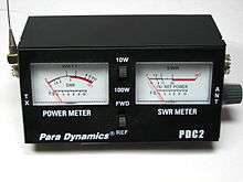
In a passive meter, this is usually indicated on a non-linear scale.

SWR Bridge
SWR can also be measured using an impedance bridge circuit. The bridge is balanced (0 volts across the detector) only when the test impedance exactly matches the reference impedance. When a transmission line is mismatched (SWR > 1:1), its input impedance deviates from its characteristic impedance; thus, a bridge can be used to determine the presence or absence of a low SWR.
To test for a match, the reference impedance of the bridge is set to the expected load impedance (for example, 50 ohms), and the transmission line connected as the unknown impedance. RF power is applied to the circuit. The voltage at the line input represents the vector sum of the forward wave, and the wave reflected from the load. If the characteristic impedance of the line is known to be 50 ohms, we know the magnitude and phase of the forward wave; it is the same wave present on the other side of the detector. Subtracting this known wave from the wave present at the line input yields the reflected wave. Properly designed, a bridge circuit can be used not only to indicate a match, but the degree of mismatch - thus making it possible to calculate the SWR. This usually involves alternately connecting the reference wave and the reflected wave to a power meter, and comparing the magnitudes of the resulting deflections.[2]
Limitations
An SWR meter does not measure the actual impedance of a load (the resistance and reactance), but only the mismatch ratio. To measure the actual impedance, an antenna analyzer or other similar RF measuring device is required. For accurate readings, the SWR meter must be matched to the line impedance, usually 50 or 75 ohms. To accommodate multiple impedances, some SWR meters have switches on the rear, to select the resistance appropriate for the sense lines.
An SWR meter should be connected to the line as close as possible to the antenna: All practical transmission lines have a certain amount of loss, which causes the reflected wave to be attenuated as it travels back along the line. Thus, the SWR is highest closest to the load, and only improves as the distance from the load increases.[3]
The internal diodes of an SWR meter may generate objectionable harmonics when transmitting and produce intermodulation products during reception, if it is left in the system after measurement. Active SWR meters do not usually suffer from this effect, and may be left in without causing such problems.
Notes
References
- The ARRL Antenna Book (21st ed.), The American Radio Relay League, Inc., 2007, ISBN 0-87259-987-6
| Wikimedia Commons has media related to SWR meters. |