Roller chain

_of_roller_chain%2C_Leonardo_da_Vinci.jpg)
Roller chain or bush roller chain is the type of chain drive most commonly used for transmission of mechanical power on many kinds of domestic, industrial and agricultural machinery, including conveyors, wire- and tube-drawing machines, printing presses, cars, motorcycles, and bicycles. It consists of a series of short cylindrical rollers held together by side links. It is driven by a toothed wheel called a sprocket. It is a simple, reliable, and efficient[1] means of power transmission.
Though Hans Renold is credited with inventing the roller chain in 1880, sketches by Leonardo da Vinci in the 16th century show a chain with a roller bearing.[2]
Construction of the chain
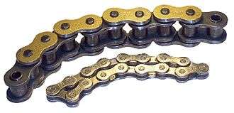
There are actually two types of links alternating in the bush roller chain. The first type is inner links, having two inner plates held together by two sleeves or bushings upon which rotate two rollers. Inner links alternate with the second type, the outer links, consisting of two outer plates held together by pins passing through the bushings of the inner links. The "bushingless" roller chain is similar in operation though not in construction; instead of separate bushings or sleeves holding the inner plates together, the plate has a tube stamped into it protruding from the hole which serves the same purpose. This has the advantage of removing one step in assembly of the chain.
The roller chain design reduces friction compared to simpler designs, resulting in higher efficiency and less wear. The original power transmission chain varieties lacked rollers and bushings, with both the inner and outer plates held by pins which directly contacted the sprocket teeth; however this configuration exhibited extremely rapid wear of both the sprocket teeth, and the plates where they pivoted on the pins. This problem was partially solved by the development of bushed chains, with the pins holding the outer plates passing through bushings or sleeves connecting the inner plates. This distributed the wear over a greater area; however the teeth of the sprockets still wore more rapidly than is desirable, from the sliding friction against the bushings. The addition of rollers surrounding the bushing sleeves of the chain and provided rolling contact with the teeth of the sprockets resulting in excellent resistance to wear of both sprockets and chain as well. There is even very low friction, as long as the chain is sufficiently lubricated. Continuous, clean, lubrication of roller chains is of primary importance for efficient operation as well as correct tensioning.
Lubrication
Many driving chains (for example, in factory equipment, or driving a camshaft inside an internal combustion engine) operate in clean environments, and thus the wearing surfaces (that is, the pins and bushings) are safe from precipitation and airborne grit, many even in a sealed environment such as an oil bath. Some roller chains are designed to have o-rings built into the space between the outside link plate and the inside roller link plates. Chain manufacturers began to include this feature in 1971 after the application was invented by Joseph Montano while working for Whitney Chain of Hartford, Connecticut. O-rings were included as a way to improve lubrication to the links of power transmission chains, a service that is vitally important to extending their working life. These rubber fixtures form a barrier that holds factory applied lubricating grease inside of the pin and bushing wear areas. Further, the rubber o-rings prevent dirt and other contaminants from entering the inside of the chain linkages, where such particles would otherwise cause significant wear.
There are also many chains that have to operate in dirty conditions, and for size or operational reasons cannot be sealed. Examples include chains on farm equipment, bicycles, and chain saws. These chains will necessarily have relatively high rates of wear, particularly when the operators are prepared to accept more friction, less efficiency, more noise and more frequent replacement as they neglect lubrication and adjustment.
Motorcycle chain lubrication
Chains operating at high speeds comparable to those on motorcycles should be used in conjunction with an oil bath.[3] For modern motorcycles this is not possible, and most motorcycle chains run unprotected. Thus, motorcycle chains tend to wear very quickly relative to other applications. They are subject to extreme forces and are exposed to rain, dirt, sand and road salt.
Motorcycle chains are part of the drive train to transmit the motor power to the back wheel. Properly lubricated chains can reach an efficiency of 98% or greater in the transmission. Unlubricated chains will significantly decrease performance and increase chain and sprocket wear.[1]
Two types of aftermarket lubricants are available for motorcycle chains: spray on lubricants and oil drip feed systems.
- Spray lubricants may contain wax or PTFE. While these lubricants use tack additives to stay on the chain they can also attract dirt and sand from the road and over time produce a grinding paste that accelerates component wear.
- Oil drip feed systems continuously lubricate the chain and use light oil that does not stick to the chain. Research has shown that oil drip feed systems provide the greatest wear protection and greatest power saving.[4]
Variants in design
.png)
If the chain is not being used for a high wear application (for instance if it is just transmitting motion from a hand operated lever to a control shaft on a machine, or a sliding door on an oven), then one of the simpler types of chain may still be used. Conversely, where extra strength but the smooth drive of a smaller pitch is required, the chain may be "siamesed"; instead of just two rows of plates on the outer sides of the chain, there may be three ("duplex"), four ("triplex"), or more rows of plates running parallel, with bushings and rollers between each adjacent pair, and the same number of rows of teeth running in parallel on the sprockets to match. Timing chains on automotive engines, for example, typically have multiple rows of plates called strands.
Roller chain is made in several sizes, the most common American National Standards Institute (ANSI) standards being 40, 50, 60, and 80. The first digit(s) indicate the pitch of the chain in eighths of an inch, with the last digit being 0 for standard chain, 1 for lightweight chain, and 5 for bushed chain with no rollers. Thus, a chain with half inch pitch would be a #40 while a #160 sprocket would have teeth spaced 2 inches apart, etc. Metric pitches are expressed in sixteenths of an inch; thus a metric #8 chain (08B-1) would be equivalent to an ANSI #40. Most roller chain is made from plain carbon or alloy steel, but stainless steel is used in food processing machinery or other places where lubrication is a problem, and nylon or brass are occasionally seen for the same reason.
Roller chain is ordinarily hooked up using a master link (also known as a connecting link), which typically has one pin held by a horseshoe clip rather than friction fit, allowing it to be inserted or removed with simple tools. Chain with a removable link or pin is also known as cottered chain, which allows the length of the chain to be adjusted. Half links (also known as offsets) are available and are used to increase the length of the chain by a single roller. Riveted roller chain has the master link (also known as a connecting link) "riveted" or mashed on the ends. These pins are made to be durable and are not removable.[5]
Use

- Roller chains are used in low- to mid-speed drives at around 600 to 800 feet per minute; however, at higher speeds, around 2,000 to 3,000 feet per minute, V-belts are normally used due to wear and noise issues.
- A bicycle chain is a form of roller chain. Bicycle chains may have a master link, or may require a chain tool for removal and installation. A similar but larger and thus stronger chain is used on most motorcycles although it is sometimes replaced by either a toothed belt or a shaft drive, which offer lower noise level and fewer maintenance requirements.
- In older automobile engines from the United States and other countries, roller chains would traditionally drive the camshaft(s) off the crankshaft, generating less noise than a gear drive as used in very high performance engines, and offering more durability than the timing belt frequently used on more modern engines. Many modern automobile engines still use roller chains, which are more durable than timing belts.
- Chains are also used in forklifts using hydraulic rams as a pulley to raise and lower the carriage; however, these chains are not considered roller chains, but are classified as lift or leaf chains.
- Chainsaw cutting chains superficially resemble roller chains but are more closely related to leaf chains. They are driven by projecting drive links which also serve to locate the chain onto the bar.
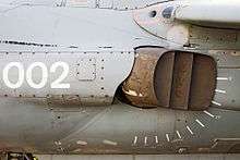
- A perhaps unusual use of a pair of motorcycle chains is in the Harrier Jump Jet, where a chain drive from an air motor is used to rotate the movable engine nozzles, allowing them to be pointed downwards for hovering flight, or to the rear for normal forward flight, a system known as Thrust vectoring.
Wear
The effect of wear on a roller chain is to increase the pitch (spacing of the links), causing the chain to grow longer. Note that this is due to wear at the pivoting pins and bushes, not from actual stretching of the metal (as does happen to some flexible steel components such as the hand-brake cable of a motor vehicle).
With modern chains it is unusual for a chain (other than that of a bicycle) to wear until it breaks, since a worn chain leads to the rapid onset of wear on the teeth of the sprockets, with ultimate failure being the loss of all the teeth on the sprocket. The sprockets (in particular the larger of the two) suffer a grinding motion that puts a characteristic hook shape into the driven face of the teeth. (This effect is made worse by a chain improperly tensioned, but is unavoidable no matter what care is taken). The worn teeth (and chain) no longer provides smooth transmission of power and this may become evident from the noise, the vibration or (in car engines using a timing chain) the variation in ignition timing seen with a timing light. Both sprockets and chain should be replaced in these cases, since a new chain on worn sprockets will not last long. However, in less severe cases it may be possible to save the smaller of the two sprockets, since it is always the larger one that suffers the most wear. Only in very light-weight applications such as a bicycle, or in extreme cases of improper tension, the chain will normally jump off the sprockets.
The lengthening due to wear of a chain is calculated by the following formula:

M = the length of a number of links measured
S = the number of links measured
P = Pitch
In industry, it is usual to monitor the movement of the chain tensioner (whether manual or automatic) or the exact length of a drive chain (one rule of thumb is to replace a roller chain which has elongated 3% on an adjustable drive or 1.5% on a fixed-center drive). A simpler method, particularly suitable for the cycle or motorcycle user, is to attempt to pull the chain away from the larger of the two sprockets. Any significant movement (e.g. making it possible to see through a gap) probably indicates a chain worn up to and beyond the limit. Sprocket damage will result if the problem is ignored.
Bicycle chain wear
The lightweight chain of a bicycle with derailleur gears can snap (or rather, come apart at the side-plates, since it is normal for the "riveting" to fail first) because the pins inside are not cylindrical, they are barrel-shaped. Contact between the pin and the bushing is not the regular line, but a point which allows the chain's pins to work its way through the bushing, and finally the roller, ultimately causing the chain to snap. This form of construction is necessary because the gear-changing action of this form of transmission requires the chain to both bend sideways and to twist, but this can occur with the flexibility of such a narrow chain and relatively large free lengths on a bicycle.
Chain failure is much less of a problem on hub-geared systems (e.g. Bendix 2-speed, Sturmey-Archer AW) since the parallel pins have a much bigger wearing surface in contact with the bush. The hub-gear system also allows complete enclosure, a great aid to lubrication and protection from grit.
Chain strength
The most common measure of roller chain's strength is tensile strength. Tensile strength represents how much load a chain can withstand under a one-time load before breaking. Just as important as tensile strength is a chain's fatigue strength. The critical factors in a chain's fatigue strength is the quality of steel used to manufacture the chain, the heat treatment of the chain components, the quality of the pitch hole fabrication of the linkplates, and the type of shot plus the intensity of shot peen coverage on the linkplates. Other factors can include the thickness of the linkplates and the design (contour) of the linkplates. The rule of thumb for roller chain operating on a continuous drive is for the chain load to not exceed a mere 1/6 or 1/9 of the chain's tensile strength, depending on the type of master links used (press-fit vs. slip-fit). Roller chains operating on a continuous drive beyond these thresholds can and typically do fail prematurely via linkplate fatigue failure.
The standard minimum ultimate strength of the ANSI 29.1 steel chain is 12,500 x (pitch, in inches)2. Internal Lubrication X-Ring and O-Ring Type chains greatly decrease wear by means of keeping in internal lubrication increasing chain life. The internal lubrication is inserted by means of a vacuum when riveting the chain together
Chain standards
Standards organizations (such as ANSI) maintain standards for design, dimensions, and interchangeability of transmission chains. For example, the following Table shows data from ANSI standard B29.1-2011 (Precision Power Transmission Roller Chains, Attachments, and Sprockets)[6] developed by the American Society of Mechanical Engineers (ASME). See the references[7][8][9] for additional information.
| ASME/ANSI B29.1-2011 Roller Chain Standard Sizes | |||||||
| Size | Pitch | Maximum Roller Diameter | Minimum Ultimate Tensile Strength | Measuring Load | |||
|---|---|---|---|---|---|---|---|
| 25 | 0.250 in (6.35 mm) | 0.130 in (3.30 mm) | 780 lb (350 kg) | 18 lb (8.2 kg) | |||
| 35 | 0.375 in (9.53 mm) | 0.200 in (5.08 mm) | 1,760 lb (800 kg) | 18 lb (8.2 kg) | |||
| 41 | 0.500 in (12.70 mm) | 0.306 in (7.77 mm) | 1,500 lb (680 kg) | 18 lb (8.2 kg) | |||
| 40 | 0.500 in (12.70 mm) | 0.312 in (7.92 mm) | 3,125 lb (1,417 kg) | 31 lb (14 kg) | |||
| 50 | 0.625 in (15.88 mm) | 0.400 in (10.16 mm) | 4,880 lb (2,210 kg) | 49 lb (22 kg) | |||
| 60 | 0.750 in (19.05 mm) | 0.469 in (11.91 mm) | 7,030 lb (3,190 kg) | 70 lb (32 kg) | |||
| 80 | 1.000 in (25.40 mm) | 0.625 in (15.88 mm) | 12,500 lb (5,700 kg) | 125 lb (57 kg) | |||
| 100 | 1.250 in (31.75 mm) | 0.750 in (19.05 mm) | 19,531 lb (8,859 kg) | 195 lb (88 kg) | |||
| 120 | 1.500 in (38.10 mm) | 0.875 in (22.23 mm) | 28,125 lb (12,757 kg) | 281 lb (127 kg) | |||
| 140 | 1.750 in (44.45 mm) | 1.000 in (25.40 mm) | 38,280 lb (17,360 kg) | 383 lb (174 kg) | |||
| 160 | 2.000 in (50.80 mm) | 1.125 in (28.58 mm) | 50,000 lb (23,000 kg) | 500 lb (230 kg) | |||
| 180 | 2.250 in (57.15 mm) | 1.460 in (37.08 mm) | 63,280 lb (28,700 kg) | 633 lb (287 kg) | |||
| 200 | 2.500 in (63.50 mm) | 1.562 in (39.67 mm) | 78,175 lb (35,460 kg) | 781 lb (354 kg) | |||
| 240 | 3.000 in (76.20 mm) | 1.875 in (47.63 mm) | 112,500 lb (51,000 kg) | 1,000 lb (450 kg) | |||
For mnemonic purposes, below is another presentation of key dimensions from the same standard, expressed in fractions of an inch (which was part of the thinking behind the choice of preferred numbers in the ANSI standard):
| Pitch (inches) | Pitch expressed in eighths | ANSI standard chain number | Width (inches) |
|---|---|---|---|
| 1⁄4 | 2⁄8 | 25 | 1⁄8 |
| 3⁄8 | 3⁄8 | 35 | 3⁄16 |
| 1⁄2 | 4⁄8 | 41 | 1⁄4 |
| 1⁄2 | 4⁄8 | 40 | 5⁄16 |
| 5⁄8 | 5⁄8 | 50 | 3⁄8 |
| 3⁄4 | 6⁄8 | 60 | 1⁄2 |
| 1 | 8⁄8 | 80 | 5⁄8 |
| Notes: 1. The pitch is the distance between roller centers. The width is the distance between the link plates (i.e. slightly more than the roller width to allow for clearance). 2. The right-hand digit of the standard denotes 0 = normal chain, 1 = lightweight chain, 5 = rollerless bushing chain. 3. The left-hand digit denotes the number of eighths of an inch that make up the pitch. 4. An "H" following the standard number denotes heavyweight chain. A hyphenated number following the standard number denotes double-strand (2), triple-strand (3), and so on. Thus 60H-3 denotes number 60 heavyweight triple-strand chain. | |||
A typical bicycle chain (for derailleur gears) uses narrow 1/2" pitch chain. The width of the chain is variable, and does not affect the load capacity. The more sprocket wheels at the back wheels confined space (historically 3-6, actually 7, 8, 9 or even 10 speeds) the narrower the chain. Hub gear or single speed bicycles use 1/2" x 1/8" chains.
Typically chains with parallel shaped links have an even number of links, with each narrow link followed by a broad one. Chains built up with a uniform type of link, narrow at one and broad at the other end, can be made with an uneven number of links, which can be an advantage to adapt to a special chainwheel-distance, on the other side such a chain tends to be not so strong.
References
- 1 2 As much as 98% efficient under ideal conditions, according to Kidd, Matt D.; N. E. Loch; R. L. Reuben (1998). "Bicycle Chain Efficiency". The Engineering of Sport conference. Heriot-Watt University. Archived from the original on 6 February 2006. Retrieved 16 May 2006.
- ↑ In the 16th century, Leonardo da Vinci made sketches of what appears to be the first steel chain. These chains were probably designed to transmit pulling, not wrapping, power because they consist only of plates and pins and have metal fittings. However, da Vinci's sketch does show a roller bearing.Tsubakimoto Chain Co., ed. (1997). The Complete Guide to Chain. Kogyo Chosaki Publishing Co., Ltd. p. 240. ISBN 0-9658932-0-0. p. 211. Retrieved 17 May 2006.
- ↑ Chains operating at high speeds comparable to those on motorcycles should be used in conjunction with an oil bath, according to: Lubrecht, A. and Dalmaz, G., (eds.) Transients Processes in Tribology, Proc 30th Leeds-Lyon Symposium on Tribology. 30th Leeds-Lyon Symposium on Tribology, 2–5 September 2003, Lyon. Tribology and Interface Engineering Series (43). Elsevier, Amsterdam, pp. 291-298.
- ↑ Oil drip feed provided the greatest wear protection between chain roller and pin, Oil drip feed provided the greatest power saving over unlubricated chains and sprockets, according to Lee, P.M. and Priest, M. (2004) An innovation integrated approach to testing motorcycle drive chain lubricants. In: Lubrecht, A. and Dalmaz, G., (eds.) Transients Processes in Tribology, Proc 30th Leeds-Lyon Symposium on Tribology. 30th Leeds-Lyon Symposium on Tribology, 2–5 September 2003, Lyon. Tribology and Interface Engineering Series (43). Elsevier, Amsterdam, pp. 291-298.
- ↑ "Riveted vs Cottered Chain - Panzit Library". panzit.com. Archived from the original on 26 April 2012. Retrieved 17 January 2015.
- ↑ ASME B29.1-2011 - Precision Power Transmission Roller Chains, Attachments, and Sprockets.
- ↑ Tsubakimoto Chain Co., ed. (1997). "Transmission Chains". The Complete Guide to Chain. Kogyo Chosaki Publishing Co., Ltd. p. 240. ISBN 0-9658932-0-0. p. 86. Retrieved 30 January 2015.
- ↑ Green 1996, pp. 2337–2361
- ↑ "ANSI G7 Standard Roller Chain - Tsubaki Europe". Tsubaki Europe. Tsubakimoto Europe B.V. Retrieved 18 June 2009.
Bibliography
- Oberg, Erik; Jones, Franklin D.; Horton, Holbrook L.; Ryffel, Henry H. (1996), Green, Robert E.; McCauley, Christopher J., eds., Machinery's Handbook (25th ed.), New York, NY, USA: Industrial Press, ISBN 978-0-8311-2575-2, OCLC 473691581.
External links
| Wikimedia Commons has media related to Roller chains. |