Railway semaphore signal
.jpg)
One of the earliest forms of fixed railway signal is the semaphore. These signals display their different indications to train drivers by changing the angle of inclination of a pivoted 'arm'. Semaphore signals were patented in the early 1840s by Joseph James Stevens, and soon became the most widely used form of mechanical signal. Designs have altered over the intervening years, and colour light signals have replaced semaphore signals in some countries, but in others they remain in use. Note that this article doesn't represent a world wide view of the semaphore.
Origins
The first railway semaphore signal was erected by Charles Hutton Gregory on the London and Croydon Railway (later the London Brighton and South Coast Railway) at New Cross, southeast London, about 1842 on the newly enlarged layout also accommodating the South Eastern Railway.[1] John Urpeth Rastrick claimed to have suggested the idea to Hutton Gregory.[2]
The semaphore was afterwards rapidly adopted as a fixed signal throughout Britain, superseding all other types in most uses by 1870. Such signals were widely adopted in the U.S. after 1908.
Form
Components
The semaphore arm consists of two parts: A wooden or metal arm (or "blade") which pivots at different angles, and a spectacle holding coloured lenses which move in front of a lamp in order to provide indications at night. Usually these were combined into a single frame, though in some types (e.g. "somersault" signals in which the arm pivoted in the centre), the arm was separate from the spectacle. The arm projects horizontally in its most restrictive aspect; other angles indicate less restrictive aspects.
The appropriately coloured lens, depending on the arm's position, is illuminated from behind by either an oil lamp, a gas lamp, or an incandescent lamp run at a low voltage (white LED clusters have also been tested for this purpose). Where a green light was required, a blue lens would usually be used. When combined with the mainly yellow-emitting flame of an oil lamp, this produced a green colour; it was important that the resultant colour was not even yellow-green in appearance, as this could have been confused for a distant signal at caution. Later signals using electric lamps used green lenses. Some signals converted to electric lamps from oil used a yellow-tinted bulb with the original blue lens to maintain the correct colour.
Materials that were commonly used to make signal posts for semaphore signals included timber, lattice steel, tubular steel and concrete. The Southern Railway in Great Britain frequently made use of old rail for signal posts.
Lower quadrant and upper quadrant

Semaphores come in lower quadrant and upper quadrant forms. In a lower quadrant signal, the arm pivots downwards for the less restrictive (known as "off") indication. Upper quadrant signals, as the name implies, pivot the arm upward for "off".
During the 1870s, all the British railway companies standardised on the use of semaphore signals, which were then invariably all of the lower quadrant type.[3] From the 1920s onwards, upper quadrant semaphores almost totally supplanted lower quadrant signals in Great Britain, except on former GWR lines.[4] The advantage of the upper quadrant signal is that should the signal wire break, or the signal arm be weighed down by snow (for instance), gravity will tend to cause the signal to drop to the safe "danger" position. In a lower quadrant signal, the opposite may happen, sending the signal to "off" when in fact it should be illustrating "danger". Their spectacle cases, which are on the opposite side of the spindle on which the signal arm is pivoted, are therefore required to be sufficiently heavy to prevent this happening.[5]
Current British practice mandates that semaphore signals, both upper and lower quadrant types, are inclined at an angle of 45 degrees from horizontal to display an "off" indication.[6]
Two-position and three-position signals
The first railway semaphore signals had arms that could be worked to three positions, in the lower quadrant. Used in conjunction with the time-interval system, the arm horizontal meant "danger", inclined downwards at 45 degrees meant "caution" and the arm vertical (arm hidden within the post) meant "clear". The vertical indication gradually came to be discontinued as the absolute block system superseded time-interval working. The Great Northern Railway was the first company to introduce "somersault" signals, mounted away from the post, after an accident in January 1876 when a train passed a signal giving a false "clear" aspect because the signal arm had frozen into its slot during a blizzard.[7]

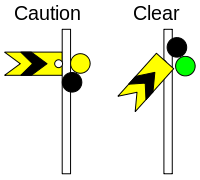
A later development was the upper quadrant three-position semaphore signal. These worked in the upper quadrant to distinguish them from the then standard two-position lower quadrant semaphores. When the arm is inclined upwards at 45 degrees, the meaning is "caution" and the arm in the vertical position means "clear". Thus, three indications can be conveyed with just one arm and without the need for a distant arm on the same post. The early abandonment of the three-position semaphore signal in the UK allowed for the widespread replacement of two-position lower quadrant signals by two-position upper quadrant signals.[8]
Colouring and shape of arm
Red was quickly chosen as the best colour for semaphore arms as it was clearly visible against most backgrounds. To enhance the visibility of the arm, a marking of contrasting colour, such as a stripe or spot, is usually applied. The rear of the arm is usually coloured white with a black marking.
Where particularly poor background contrast cannot be avoided, a sighting board (usually painted white) can be placed behind the arm to provide adequate contrast which improves visibility. Alternatively, part of a bridge abutment conveniently located behind a signal may be painted white.
From 1872, distant signal arms (see below) were distinguished by having a "fishtail" notch cut into the end. All signal arms were still painted red at this time. In the 1920s, the British railway companies began to colour their distant signal arms yellow to better distinguish them from the red stop signals. The red lenses in distant signals were changed to yellow at the same time. The practice of using red distant arms has survived in some countries however.
A third type of arm with a pointed end extending outward is often used (though not in the UK) to indicate that the signal operates automatically (as in automatic block signalling systems) and in many cases indicates that the signal is 'permissive', and can be passed when showing its most restrictive aspect, at a low speed.
For most types of semaphore arm, the colour of light shown when the arm is in the "on" (most restrictive) position generally corresponds to the colour of the arm itself (i.e. red for a stop signal, yellow for a distant signal). When the arm is in the "off" position, a green light is displayed.
Other shapes and colours of semaphore arms were used for specific purposes in different countries around the world.
Operation

The first semaphore signals were controlled by levers situated at the signals. Some early signals protruded from the roof of the controlling signal box. Later, remote operation was effected by levers connected to the signal by single wires (UK), pairs of wires (Continental Europe), or pipes supported on rollers (US). The levers were grouped together in a building known as a "signal box" (UK & Australia) or "interlocking tower" (US). In the UK multiple signal wires were grouped together, and in station areas were commonly routed beneath platform faces just above rail level. The operation of a single signal wire would cause some of the adjacent wires to 'jangle', and this noise was one of the many characteristic sounds of railway travel until the gradual introduction of colour-light signals from the mid 20th century.
Semaphore signals may also be operated by electric motors, hydraulically or pneumatically, allowing them to be located further from the controlling signal box. In some cases, they can be made to work automatically. The signals are designed to be fail-safe so that if power is lost or a linkage is broken, the arm will move by gravity into the horizontal position. For lower quadrant semaphores this requires the spectacle case to be sufficiently heavy to ensure the arm rises rather than falls; this is one of the reasons for the widespread switch to upper quadrant signals. (The purpose of the balance weight often found on a lever lower down the post of a semaphore signal is actually to ensure the signal wire returns to its normal position when the controlling lever is put back. Otherwise, again, the signal could fail to return to danger. These counterweights are used just as commonly on upper- as on lower-quadrant signals.)
Usage
Stop signals

A stop signal (US - home signal or absolute signal) is any signal whose most restrictive indication is 'danger' (which compels a stop). Stop signals are used to protect junctions, points (US - 'switches'), level crossings, movable bridges, platforms or block sections.
A particular signal box may control one or more stop signals on each running line. In a traditional mechanically signalled area, it is most common for a signal box to have two stop signals governing each line. The first reached by a train is known as the home signal. The last stop signal, known as the starting or section signal, is usually located past the points etc. and controls entry to the block section ahead. The distance between the home and starting signals is usually quite short (typically a few hundred yards), and allows a train to wait for the section ahead of it to clear without blocking the line all the way back to the previous stop signal.
Outer home
At some locations, more than one home signal might be provided on the same line. These will be identified by names such as outer home and inner home, or first home, second home etc.
An outer home protects a neutral long of a quarter of a mile (440yards/400m) clear of any points or sidings. This allows trains to approach when the station or junction is obstructed. It is noted that the junction in the Sunshine rail accident did not have outer home signals.
Advanced starting
An advanced starting signal might be used at a location where it might be desirable to advance a train from a station platform before the section ahead becomes available. In this scenario, the starting signal permits the train to draw forward from the station area toward the advanced starting signal, which controls entry to the section ahead.
If any of the signals beyond the first stop signal are at 'danger', the previous signals will also be held at 'danger' until the train is almost at a stand, to indicate to the driver that the next signal is at 'danger'. This can be enforced by instruction or by electrical interlocking, which requires the provision of a track circuit on the approach to the signal.
In North America, the foregoing terminology was not used, as the development of American signalling practice diverged from that in the United Kingdom during the late nineteenth century. In America, where the term home signal is in common usage, it generally refers to the "generic" British definition of 'stop signal', namely any signal whose most restrictive indication is 'danger'.
Distant signals
A signal that provides advance warning of a stop signal ahead (and which does not compel a stop when in its most restrictive position) is referred to as distant signal. The term originated in the UK and is used throughout the English-speaking world. In some regions, notably North America, the terms distant signal and approach signal are both in common usage.
Because of the long distance required to bring a moving train to a stand, distant signals must be located on the approach to the corresponding stop signal by at least the braking distance of the worst braked train to use the route. This is particularly important on high-speed routes. At one time it was practice to take sighting distance into account when positioning distant signals; the distant signal could therefore be positioned at less than braking distance to the corresponding stop signal.
The driver of a train encountering a distant signal at 'caution' must expect the stop signal to be at 'danger' and must adjust the train's speed so as to bring the train to a stand before reaching it. The driver of a train encountering a distant signal in the 'clear' position knows that all applicable stop signals controlled by the same signal box are in the 'clear' position.
This is enforced by interlocking; the distant signal is prevented from assuming the 'clear' position unless all relevant stop signals controlled by the signal box display 'clear'.

Changes in colour and meaning
Until the 1920s, distant signals were coloured red, with a red light at night. Given that their meanings were different, it was obviously unsatisfactory to have both home and distant signals showing the same colour, but one of the problems which delayed a change in the colour of distant signals to yellow was the lack of a suitable yellow glass for the spectacle frame.[9] Some British railway companies used the Coligny-Welch signal lamp to clarify night aspects; this was fitted to distant signals and showed a white vee in addition to the main red or green light. The Ministry of Transport recommended that the colour of distant signal arms and spectacles be altered from red to yellow in the early 1920s, although this was not universally adopted in the UK until the late 1920s. Since this time, the yellow caution aspect has remained a British railway standard.
The Victorian Railways in Australia changed only isolated distant signals, leaving combined home and distant signals showing green over red at the caution position. The New South Wales Government Railways retained the red distant signal everywhere, adding a fixed upper green light so that an isolated distant signal displayed green over red, like a combined home and distant signal at caution. [10]
In the 19th century, a distant signal on the Victorian Railways required the train to stop when the signal was at red, not just to proceed with caution as is the case now. However, having stopped at a distant signal at red, the train could then proceed carefully to the home signal, being prepared to stop short of any obstruction between the two signals. Thus the distant signal at that time was a bit like a later "outer home" signal. That practice at a distant signal at that time may have been a factor in the Sunshine rail accident of 1908.
Combined stop and distant signals

Where signals are closely spaced, a stop signal and a distant signal can be mounted on the same post. The distant signal is always the lower of the two. The two signals are "slotted" so that the distant signal can only clear if the stop signal is clear. Both signals display a light at night, which means that the 'danger' indication appears as red over yellow.
Exceptionally in New South Wales home and distant signals controlled from the same signal box would be installed, especially on outer home signals.
Shunting and subsidiary signals
Shunting signals and subsidiary signals also exist in semaphore form, with smaller arms and lights than are provided for main signals. These signals may also take the form of a disc with a horizontal stripe which is rotated 45 degrees to the clear position.
Train order signals
In North America, semaphores were employed as train order signals,[11] with the purpose of indicating to engineers whether they should stop to receive a telegraphed order. It was common for train order signals to point the arm straight down to indicate 'proceed'. Train order signals were typically located at the station building, with a tall common post mounting signal arms facing in opposing directions.
Non-railway uses
Railway-style semaphore signals have been used to control movements of boats or ships (e.g. at swing bridges) and also to control road traffic (e.g. at level crossings).
Decline in usage

Mechanical signals worldwide are being phased out in favour of colour light signals or, in some cases, signalling systems that do not require lineside signals (e.g. RETB and the new European system ERTMS). In the United States, their usage has been almost completely eliminated on main lines, with significant remaining installations still found on two separate segments of the CSX Transportation line from Louisville, Kentucky to Chicago, Illinois, on the route of the former Monon Railroad, and on the BNSF Railway's Glorieta Subdivision in New Mexico, which is used by Amtrak's Chicago-Los Angeles passenger train, the Southwest Chief.
In the UK, semaphore signals are still quite common on the rail network on secondary routes, however the increase in spending on renewals is leading to a faster rate of decline in recent years.
New railways in undeveloped countries lacking reliable electrical supplies continue to use mechanical points and signals, such as the TAZARA Railway in Tanzania and Zambia which was built in the 1970s.
See also
References
- ↑ Dendy Marshall, C.F., revised by R.W. Kidner (1963). A History of the Southern Railway. London: Ian Allan. p. 50..
- ↑ The National Archives RAIL 386.58.
- ↑ Vanns, M.A., (1997), An Illustrated History of Signalling, Ian Allan, ISBN 0-7110-2551-7, p.25
- ↑ Vanns, M.A., (1995), Signalling in the Age of Steam, Ian Allan, ISBN 0-7110-2350-6, p.80
- ↑ Kichenside, G.M. & Williams, Alan, (1978), British Railway Signalling, Fourth Edition, Ian Allan, ISBN 0-7110-0898-1, p.15
- ↑ Railway Group Standard GK/RT0031
- ↑ Rolt, L.T.C. (1955). Red for Danger. London: John Lane. p. 120.
- ↑ Vanns, M.A., (1997), An Illustrated History of Signalling, Ian Allan, ISBN 0-7110-2551-7, p.75
- ↑ "A Third Colour for Railway Signals.". The Bunbury Herald and Blackwood Express (WA : 1919 - 1929). WA: National Library of Australia. 17 September 1926. p. 3. Retrieved 31 January 2013.
- ↑ "WONGARBON.". The Dubbo Liberal and Macquarie Advocate (NSW : 1892 - 1927). NSW: National Library of Australia. 4 November 1927. p. 5. Retrieved 31 January 2013.
- ↑ Calvert, J.B. (2004). "Train Order Signals." Railways: History, Signalling, Engineering.