Radio receiver design
Radio receiver design includes the electronic design of different components of a radio receiver which processes the radio frequency signal from an antenna in order to produce usable information such as audio. This article only concentrates on the historical configurations leading up to and including the modern superheterodyne receiver design. The complexity of a modern receiver and the possible range of circuitry and methods employed are more generally covered in electronics and communications engineering. The term radio receiver is understood in this article to mean any device which is intended to receive a radio signal in order to generate useful information from the signal, most notably a recreation of the so-called baseband signal (such as audio) which modulated the radio signal at the time of transmission in a communications or broadcast system.
Crystal radio
A crystal radio uses no active parts: it is powered only by the radio signal itself, whose detected power feeds headphones in order to be audible at all. In order to achieve even a minimal sensitivity, a crystal radio is limited to low frequencies using a large antenna (usually a long wire). It relies on detection using some sort of semiconductor diode such as the original cat's-whisker diode discovered long before the development of modern semiconductors.

- Advantages
- Simple, easy-to-make. Here we see a classic design for a clandestine receiver in a POW camp.
- Disadvantages
- Insensitive, it needs a strong RF signal and/or a long-wire antenna to operate.
- Poor selectivity since it only has one tuned circuit.
Tuned radio frequency
The tuned radio frequency receiver (TRF) consists of a radio frequency amplifier having one or more stages all tuned to the desired reception frequency. This is followed by a detector, typically an envelope detector using a diode, followed by audio amplification. This was developed after the invention of the triode vacuum tube, greatly improving the reception of radio signals using electronic amplification which had not previously been available. The greatly improved selectivity of the superheterodyne receiver overtook the TRF design in almost all applications, however the TRF design was still used as late as the 1960s among the cheaper "transistor radios" of that era.
Reflex
The reflex receiver was a design from the early 20th century which consists of a single-stage TRF receiver but which used the same amplifying tube to also amplify the audio signal after it had been detected. This was in an era where each tube was seen as a major cost (and recipient of electrical power) so that a substantial increase in the number of passive elements would be seen as preferable to including an additional tube. The design tends to be rather unstable, and is obsolete.
Regenerative

The regenerative receiver also had its heyday at the time where adding an active element (vacuum tube) was considered costly. In order to increase the gain of the receiver, positive feedback was used in its single RF amplifier stage; this also increased the selectivity of the receiver well beyond what would be expected from a single tuned circuit. The amount of feedback was quite critical in determining the resulting gain and had to be carefully adjusted by the radio operator. Increasing the feedback beyond a point caused the stage to oscillate at the frequency it was tuned to.
Self-oscillation reduced the quality of its reception of an AM (voice) radio signal but did ironically make it useful as a CW (Morse code) receiver inasmuch as the beat signal between the oscillation and the radio signal would produce an audio "beeping" sound. The oscillation of the regenerative receiver could also be an annoying source of local interference. An improved design known as the super-regenerative receiver improved the performance by allowing an oscillation to build up which was then "quenched", with that cycle repeating at a rapid (ultrasonic) rate. From the accompanying schematic for a practical regenerative receiver, one can appreciate its simplicity in relation to a multi-stage TRF receiver, while able to achieve the same level of amplification through the use of positive feedback.
Direct conversion
In the Direct conversion receiver, the signals from the antenna are only tuned by a single tuned circuit before entering a mixer where they are mixed with a signal from a local oscillator which is tuned to the carrier wave frequency of the transmitted signal (unlike the superheterodyne design, where the local oscillator is at an offset frequency). The output of this mixer is thus audio frequency, which is passed through a low pass filter into an audio amplifier which may drive a speaker.
For receiving CW (morse code) the local oscillator is tuned to a frequency slightly different from that of the transmitter in order to turn the received signal into an audible "beep."
- Advantages
- Simpler than a superheterodyne receiver
- Disadvantages
- Poor rejection of strong signals at adjacent frequencies compared to a superheterodyne receiver.
- Increased noise or interference when receiving a SSB signal since there is no selectivity against the undesired sideband.
Superheterodyne
Practically all modern receivers are of the superheterodyne design. The RF signal from the antenna may have one stage of amplification to improve the receiver's noise figure, although at lower frequencies this is typically omitted. The RF signal enters a mixer, along with the output of the local oscillator, in order to produce a so-called intermediate frequency (IF) signal.[1] The local oscillator is tuned to a frequency somewhat higher (or lower) than the intended reception frequency so that the IF signal will be at a particular frequency where it is further amplified in a narrow-band multistage amplifier. Tuning the receiver involves changing the frequency of the local oscillator, with further processing of the signal (especially in relation to increasing the receiver) conveniently done at a single frequency (the IF frequency) thus requiring no further tuning for different stations.
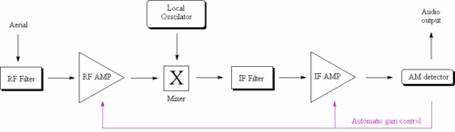
Here we show block diagrams for typical superheterodyne receivers for AM and FM broadcast respectively. This particular FM design uses a modern phase locked loop detector, unlike the frequency discriminator or ratio detector used in earlier FM receivers.

For single conversion superheterodyne AM receivers designed for medium wave (AM broadcast) the IF is commonly 455 kHz. Most superheterodyne receivers designed for broadcast FM (88 - 108 MHz) use an IF of 10.7 MHz. TV receivers often use intermediate frequencies of about 40 MHz. Some modern multiband receivers actually convert lower frequency bands first to a much higher frequency (VHF) after which a second mixer with a tunable local oscillator and a second IF stage process the signal as above.
See also
Further reading
- Books
- Radiocommunication handbook (RSGB), ISBN 0-900612-58-4
- Patents
- U.S. Patent 1,748,435 Crystal Radio Apparatus. H. Adams
Notes and references
- ↑ In tube radios the functions of the local oscillator and mixer were frequently combined in a single stage called a converter often using a pentagrid converter tube.