Plotting board
A plotting board was a mechanical device used by the U.S. Coast Artillery to track the observed course of a target (typically a moving ship), project its future position, and derive the uncorrected data[1] on azimuth (or direction) and range needed to direct the fire of the guns of a battery to hit that target. Plotting boards of this sort were first employed by the Coast Artillery[2] around 1905, and were the primary means of calculating firing data until WW2.[3]
Although several different types of plotting boards were used by the Coast Artillery over the years, the example described here is the Whistler-Hearn Plotting Board, Model of 1904 which was widely employed by the Coast Artillery between about 1905 and 1925.[4] This description is primarily derived from two manuals of the period, each of which leaves certain aspects of the board's design and use unexplained.[5][6] A 1940 manual also describes the Whistler-Hearn board.[7]
Overview
The Whistler-Hearn plotting board[8] (see Plate XXV at right, top) was a semicircular wooden table about 7.5 feet in diameter with a mechanism on top that could be configured to represent the geography of the harbor area in which it was used, including the locations of the base end stations that observed targets for the gun battery it controlled and the location of the gun/s of that battery.[9]
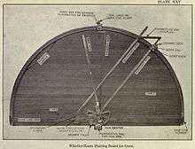

The mechanism of radial arms and adjustable slides, arcs, and gears converted observations that had been telephoned in from the base end stations into firing data for the guns[10]
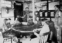
The plotting board for a given gun battery was located in the plotting room for that battery (shown at right, bottom), a space often attached to an observation post or protected within a reinforced concrete bunker or casemate. It was served by a large crew (often more than a dozen soldiers) who were part of the Range Section of the battery personnel.[11]
To locate a target, plotting board operators used two radial arms (called the primary and auxiliary arms), and "locked-in" the ends of these arms along on the notched azimuth scale that ran around the circumference of the board at the azimuths of the sightings that were telephoned in to them by the two base end stations. These locked arms and the baseline arm (along the base of the arc) then formed a triangle whose vertices were the two observation stations and the target. This located the target on the board,[12] and its position was then marked by punching a hole in the paper placed over the plotting board. Next, another radial arm, called the gun arm, was swung over the plotted position of the target, and the resulting range and azimuth for firing were read off the gun arm and an azimuth scale on the gun arm center. These data were corrected or adjusted for some other variables, and telephoned to the gun/s.
The figure at left shows the actual relationship between the distant target (at top), the two base end stations (at either end of the baseline), and the directing point of the battery's guns, as reflected onto the plotting board. The triangle formed by the B1 (primary) arm, the B2 (secondary) arm and the base line arm is the small triangle at the base of the plotting board, and the gun arm is shown swung over the intersection of the other two arms in order to read the range and azimuth to the target. Another helpful diagram is shown on the base end station page—the cutaway diagram of a battery's plotting room (with its plotting board), shown next to the two base end stations, and behind the directing point of the battery, between its two guns.
Customizing the Plotting Board To Its Site
Before it was used, a Whistler-Hearn board had to be set up and customized to the geography of the area at which it was to be used and for the location of the guns in the battery it was to direct.
First, the primary block (representing the primary base end station) was slid onto to the bronze base-line arm (that extended all the way across the bottom diameter of the table) and secured at the exact center of that arm. Then, the secondary block (representing the secondary base end station) was slid onto the left or right end of the base-line arm (depending of the layout of the site) and set at a distance from the primary block that was equal to the (scaled) length of the base line at that site.[13]
Both the primary and the secondary block had a pintle, or pin, attached to it which represented (on the board) the surveyed position of the observing instrument in the primary or secondary base end station.
The secondary arm was installed on the pintle of the secondary block. On the pintle of the primary block were installed the primary arm, the auxiliary arm,[14] and the gun arm, as well as the complex gun arm center mechanism that was used to adjust the board for the location of the guns' directing point, to read the azimuth to the target, to adjust the firing data, and to tally the motion of the target between successive plotted positions. Plate XXVI (below, at right) shows a close-up of the gun arm center mechanism.
The arc of the board was notched at one-degree intervals. To identify these notches with actual degrees of azimuth for a particular site, a zinc strip, with numbers of degrees of azimuth inscribed on it, was slipped into a slot on the surface of the board, towards its outer edge. The azimuth indicated by left edge of the base line arm was arbitrarily determined to be whatever azimuth fit the site, and adjusting screws with a vernier scale allowed for up to .5 degrees of "tweaking" of the base line arm's orientation.
Next, two index boxes were slid onto the notched circumference edge of the board and the ends of the primary and auxiliary arms were inserted into these boxes. These boxes could be locked in position at whole-degree intervals (their teeth engaged the azimuth notches around the board), and each index box had a geared dial on its surface (with 100 teeth) that could be turned through one hundred parts of a degree, enabling each arm to be adjusted to within .01 degree of azimuth.
Next, the gun arm center mechanism was slid from side to side and/or up and down with relation to the base line arm to account for the location of the battery's directing point to one side or the other of the primary base end station or behind or in front of the base line. These adjustments resulted in relocating (relating) the firing data sent to the guns to the actual (surveyed and calculated)) positions of these guns.[15]
After these adjustments, the plotting board represented a true analog of the harbor being defended (see figure at left above) and was ready for use in fire control.
This customization of the board to its site, however, was also a weakness. It meant that the battery's fire control system was limited to using only the one baseline and only the two base end stations associated with that baseline.[16] If one of the two base end stations was put out of action (due to enemy fire or something like the failure of a phone line) the battery would have to switch to a less precise method of fire control, such as vertical base observation (using a Depression Position Finder), the use of a self-contained rangefinder instrument, or aiming its guns directly, using their own telescopic sights.[17]
Using the Plotting Board
Using the plotting board required a team of five or six soldiers to handle the board itself, five or six more to handle equipment used to correct and adjust the resulting target coordinates[18] and a minimum of four more in the two distant base end stations. Many of the plotting board functions described below were performed repeatedly, during several successive observation/firing intervals (see Figure 1 below, left) that were indicated throughout the harbor defense system by the ringing of time interval bells .
The process began when a target (e.g., an enemy ship) was identified by the harbor command and assigned to a given gun battery.[19] Observers in the two widely separated base end stations for the chosen battery tracked the target, using either azimuth scopes or more sophisticated depression position finders (DPFs).[20]
At the signal from the time interval bell, the reader in each base end station would read the azimuth of the target off of the instrument (to hundredths of a degree) and (using a headset phone) call this reading to the arm setter covering that station at the plotting board. Each of the two arm setters at the board moved his assigned arm (the primary or auxiliary arm) to the position on the notched azimuth scale (which ran around the circumference of the board) that corresponded to the azimuth reading (in whole degrees) he had just received by phone from his base end station. The arm setter then locked his arm at that position, using the index disk clamp at the end of the arm. Hundredths of a degree were indicated by turning the geared index disk, a wheel with 100 teeth that enabled adjusting the angle of the arm very precisely.
With both arms set, a small block called the targ was slid up to the intersection of the arms and a mark was made on the plotting paper at the target's indicated position.
This process of observing, setting the arms on the plotting board, and marking the target's position at the arms' intersection was repeated at the end of each observing interval for the battery.[21] The interval was usually set at 20 seconds in length.[22] After tracking a target for a short time, there would a string of plotted positions indicated on the board (e.g., the blue circles shown in Figure 1 above, left). This would then be sufficient for the plotting room to "connect the dots" with a projected course line (the black line in Figure 1) and estimate the target's speed.
Next, a slide rule-like device called a set forward rule was used to mark off the set forward point (the green square in Figure 1) for the target. The set forward point was the anticipated position of the target at the end of the dead time plus the time of flight (see Figure 1).[23] The speed of the target was calculated from the time it took to cover the distances between the previously plotted points on its track.[24]
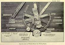
It was the set forward point that the guns were targeted to hit. This was accomplished by bringing the gun arm of the plotting board over this point, and reading the range from the directing point to the target off the range scale on the edge of that arm and the azimuth from the directing point to the target off of azimuth circle of the gun arm center. To see how this and further steps in the fire control process were accomplished, our attention shifts to the mechanisms of the gun arm center, shown in Plate XXVI at the right.
Plate XXVI shows the gun arm (although the range scale on its edge is not visible), which points here toward the top of the photo (in the 11:30 position). It also shows the window (labeled at bottom center) through which the azimuth of the gun arm was read. Many of the other features of the gun arm center were used in correcting the firing data.
Corrections in range were applied by turning the knob attached to a gear wheel (labeled "pinion" in Plate XXVI) at the center of the correction box, which slid the gun arm towards its circumference or back, with the adjustments indicated by index numbers visible through the window to the left of the pinion. Corrections in azimuth were achieved by turning the knurled knob at the right edge of the worm gear located at the bottom of the gun arm, with its pointer being used to read off index numbers and turn the gun arm through its arc.
The dials on the face of the gun arm center were used to calculate the angular travel (in degrees and hundredths) of the target between successive plotted points on the board, a quantity that could be corrected (using output from a deflection board) and then applied to calculating the set forward point.
See also
References
- ↑ Before firing, the uncorrected firing data from the plotting board were corrected to account for such factors as the current weather, the level of the tide, the batch of powder being used by the guns, and/or were adjusted based on observations from spotters who reported on the fall of earlier shots at the same target. For details, see corrected firing data.
- ↑ Other types of plotting boards, used for the field artillery, are not described here.
- ↑ Towards the end of WW2 these boards were largely replaced by radar and electro-mechanical gun data computers, and were relegated to a back-up role.
- ↑ Other boards included the Cloke plotting and relocating board and the so-called 110 Degree plotting board. For a summary see "Coast Artillery Plotting Boards 1904-1945" by Fredrick M. Baldwin, in "American Seacoast Defenses: A Reference Guide," Mark A. Berhow, Ed., CDSG Press, McLean, VA, 2004
- ↑ "The Service of Coast Artillery," Frank T. Hines and Franklin W. Ward, Goodenough & Woglom Co., New York, 1910, p. 315 ff. Plates XXV and XXVI on this page are from this source.
- ↑ "Training Manual No. 1669: Description of the Whistler-Hearn Plotting Board (Model of 1904), Mortar Plotting Board (Model of 1906 and Model of 1906 MI), and Submarine Plotting Board (Model of 1906) and Instructions for Assembling, Adjusting, Caring the, Etc.," Ordnance Department, U.S. Army, Government Printing Office, Washington, April 24, 1907, Revised December 13, 1909. This source contains engineering quality drawings of the board's mechanisms, including plans and elevations, but these are incompletely annotated.
- ↑ "FM 4-15 Coast Artillery Field Manual-Seacoast Artillery Fire Control and Position Finding," U.S. War Department, Government Printing Office, Washington, 1940, p. 84ff.
- ↑ It has been about 90 years since the Whistler-Hearn plotting board was widely used, and the details of its operation must be inferred from manuals and drawings of the period.
- ↑ The guns were located with reference to their directing point, the point for which the firing data were calculated. Making the firing data relative to the osition/s of the gun/s was called the relocation of these data. Relocation was part of the analog function of the plotting board and was enabled by adjustments to the gun arm center of the board (see plate and explanation below)
- ↑ .
- ↑ A thorough overview of how the Coast Artillery fire control process was organized and staffed and how the plotting board was employed is contained in "Gun Battery Organization and Duties I: HQ and Range Sections (1940) in "American Seacoast Defenses: A Reference Guide," Mark A. Berhow, Ed., CDSG Press, McLean, VA, 2004.
- ↑ It should be noted that the target was not located by direct triangulation from the observations of the base end stations, even though the locations of these stations and the distance between them as well as their observing angles to the target were known. Rather it was the plotted position, relative to these stations and the DP, that was computed on the board.
- ↑ The usual scale for this type of plotting board was 300 yards to the inch, and the secondary station could be located on the baseline arm to the nearest scaled yard. If the secondary block was placed on the left-hand side of the primary block (as the user looked toward the arced edge of the board), the board was called "left-handed" (like the boards shown in all three images above)."
- ↑ The offset between the secondary arm and the auxiliary arm was maintained by a connecting bar, which precisely represented (at the scale of the board) the length of the base line between the two base end stations.
- ↑ A further adjustment might need to be made by the gun crew to account for the distance of an individual gun from the battery's directing point, called its displacement.
- ↑ It was possible to reconfigure a Whistler-Hearn plotting board (by changing out the zinc strip around its circumference that held the actual azimuth values), by resetting the primary and secondary blocks on base line arm, and by readjusting the location of the gun arm center mechanism, but these adjustments were probably too complicated and time-consuming to be carried out during a battle.
- ↑ Plotting boards developed in the 1920s (like the Cloke board) could more easily be adapted to various baselines in the harbor area and have their base end stations reconfigured more quickly on the board.
- ↑ Ancillary plotting board equipment could include the range correction board, deviation correction board, spotting board, percentage corrector, and/or fire adjustment board.
- ↑ The target might have been first discovered by the observers in one of the chosen battery's base end stations, or it might have first been observed by another station. Large harbors often had a network of 20 to 30 base end stations covering all approaches to the harbor with an extensive network of telephone lines linking these stations, the harbor command, and the gun batteries.
- ↑ Azimuth scopes were only capable of locating the target in azimuth (bearing), while a DPF could be used for azimuth readings alone or could also measure the range from the base end station to the target.
- ↑ Since the firing of the gun/s often occurred when the interval bell rang, the interval was also called a firing interval.
- ↑ A very skilled battery (Range Section and gun crew) could handle an observing interval of 15 seconds, while a poorly trained battery might have trouble in following a 30 second interval schedule. Batteries drilled intensively to make their interval shorter, thus increasing their chances of putting more shots on the target per unit of time.
- ↑ The dead time was the time between the time that the observations upon which the firing data were based had been taken and the time the guns were fired. The time of flight was just that--the time it took the projectile to reach the target after it was fired.
- ↑ This type of fire control in the Coast Artillery was based upon the assumptions that the target steered in straight line and did not alter its speed during the 20-second (or longer) observing interval (or multiple intervals).