Pinhole camera
A pinhole camera is a simple camera without a lens but with a tiny aperture, a pinhole – effectively a light-proof box with a small hole in one side. Light from a scene passes through the aperture and projects an inverted image on the opposite side of the box, which is known as the camera obscura effect.
History
Sometimes it is mistakenly claimed that for instance Alhazen (965–1039) or earlier philosophers already used pinhole cameras, while in most instances the "cameras" that were originally described were either natural occurrences of the camera obscura effect or experiments with darkened rooms (or chambers) with an opening much larger than a pinhole. The claims are mainly a result of many descriptions of the history of the camera lacking differentiation between the camera obscura effect, camera obscura rooms, camera obscura boxes (usually with a lens), or actual pinhole cameras. Most usage of the camera obscura before it was fitted with a lens in the 16th century can arguably be regarded as "hole cameras". However, this would mainly concern rooms that were darkened (leaving a small opening in a shutter) to study the behavior of light or the projected image of the sun.
The oldest known description of pinhole photography is found in the 1856 book The Stereoscope by Scottish inventor David Brewster, including the description of the idea as "a camera without lenses, and with only a pin-hole". One older use of the term "pin-hole" in the context of optics was found in James Ferguson's 1764 book Lectures on select subjects in mechanics, hydrostatics, pneumatics, and optics.[1]
Sir William Crookes and William de Wiveleslie Abney were other early photographers to try the pinhole technique.[2]
Usage
The image of a pinhole camera may be projected onto a translucent screen for real-time viewing (used for safe observation of solar eclipses) or to trace the image on paper. But it is more often used without a translucent screen for pinhole photography with photographic film or photographic paper placed on the surface opposite to the pinhole aperture.
A common use of pinhole photography is to capture the movement of the sun over a long period of time. This type of photography is called solargraphy. Pinhole photography is used for artistic reasons, but also for educational purposes to let pupils learn about, and experiment with, the basics of photography.
Pinhole cameras with CCDs (charge coupled devices) are sometimes used for surveillance because they are difficult to detect.
Related cameras, image forming devices, or developments from it include Franke's widefield pinhole camera, the pinspeck camera, and the pinhead mirror.
Characteristics of pinhole camera photography
- Pinhole photographs have nearly infinite depth of field, everything appears in focus.
- As there's no lens distortion, wide angle images remain absolutely rectilinear.
- Exposure times are usually long, resulting in motion blur around moving objects and the absence of objects that moved too fast.
Other special features can be built into pinhole cameras such as the ability to take double images by using multiple pinholes, or the ability to take pictures in cylindrical or spherical perspective by curving the film plane.
Construction
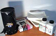
Pinhole cameras can be handmade by the photographer for a particular purpose. In its simplest form, the photographic pinhole camera can consist of a light-tight box with a pinhole in one end, and a piece of film or photographic paper wedged or taped into the other end. A flap of cardboard with a tape hinge can be used as a shutter. The pinhole may be punched or drilled using a sewing needle or small diameter bit through a piece of tinfoil or thin aluminum or brass sheet. This piece is then taped to the inside of the light-tight box behind a hole cut through the box. A cylindrical oatmeal container may be made into a pinhole camera.
The interior of an effective pinhole camera is black to avoid any reflection of the entering light onto the photographic material or viewing screen.[3]
Pinhole cameras can be constructed with a sliding film holder or back so the distance between the film and the pinhole can be adjusted. This allows the angle of view of the camera to be changed and also the effective f-stop ratio of the camera. Moving the film closer to the pinhole will result in a wide angle field of view and a shorter exposure time. Moving the film farther away from the pinhole will result in a telephoto or narrow angle view and a longer exposure time.
Pinhole cameras can also be constructed by replacing the lens assembly in a conventional camera with a pinhole. In particular, compact 35 mm cameras whose lens and focusing assembly have been damaged can be reused as pinhole cameras—maintaining the use of the shutter and film winding mechanisms. As a result of the enormous increase in f-number while maintaining the same exposure time, one must use a fast film in direct sunshine.
Pinholes (homemade or commercial) can be used in place of the lens on an SLR. Use with a digital SLR allows metering and composition by trial and error, and is effectively free, so is a popular way to try pinhole photography.[4]
Unusual materials have been used to construct pinhole cameras, e.g., a Chinese roast duck.[5] by Martin Cheung
Selection of pinhole size
Up to a certain point, the smaller the hole, the sharper the image, but the dimmer the projected image. Optimally, the size of the aperture should be 1/100 or less of the distance between it and the projected image.
Within limits, a smaller pinhole (with a thinner surface that the hole goes through) will result in sharper image resolution because the projected circle of confusion at the image plane is practically the same size as the pinhole. An extremely small hole, however, can produce significant diffraction effects and a less clear image due to the wave properties of light.[6] Additionally, vignetting occurs as the diameter of the hole approaches the thickness of the material in which it is punched, because the sides of the hole obstruct the light entering at anything other than 90 degrees.
The best pinhole is perfectly round (since irregularities cause higher-order diffraction effects), and in an extremely thin piece of material. Industrially produced pinholes benefit from laser etching, but a hobbyist can still produce pinholes of sufficiently high quality for photographic work.
One method is to start with a sheet of brass shim or metal reclaimed from an aluminium drinks can or tin foil/aluminum foil, use fine sand paper to reduce the thickness of the centre of the material to the minimum, before carefully creating a pinhole with a suitably sized needle.
A method of calculating the optimal pinhole diameter was first attempted by Jozef Petzval. The crispest image is obtained using a pinhole size determined by the formula[7]

where d is pinhole diameter, f is focal length (distance from pinhole to image plane) and λ is the wavelength of light.
For standard black-and-white film, a wavelength of light corresponding to yellow-green (550 nm) should yield optimum results. For a pinhole-to-film distance of 1 inch (25 mm), this works out to a pinhole 0.24 mm in diameter.[8] For 5 cm, the appropriate diameter is 0.33 mm.[9]
The depth of field is basically infinite, but this does not mean that no optical blurring occurs. The infinite depth of field means that image blur depends not on object distance, but on other factors, such as the distance from the aperture to the film plane, the aperture size, and the wavelength(s) of the light source.


In the 1970s, Young measured the resolution limit of the pinhole camera as a function of pinhole diameter[10] and later published a tutorial in The Physics Teacher.[11] Partly to enable a variety of diameters and focal lengths, he defined two normalized variables: pinhole radius divided by resolution limit, and focal length divided by the quantity s2/λ, where s is the radius of the pinhole and λ is the wavelength of the light, typically about 550 nm. His results are plotted in the figure.
To the left, the pinhole is large, and geometric optics applies; the resolution limit is about 1.5 times the radius of the pinhole. (Spurious resolution is also seen in the geometric-optics limit.) To the right, the pinhole is small, and Fraunhofer diffraction applies; the resolution limit is given by the far-field diffraction formula shown in the graph and now increases as the pinhole is made smaller. In the region of near-field diffraction (or Fresnel diffraction), the pinhole focuses the light slightly, and the resolution limit is minimized when the focal length f (the distance between the pinhole and the film plane) is given by f = s2/λ. At this focal length, the pinhole focuses the light slightly, and the resolution limit is about 2/3 of the radius of the pinhole. The pinhole in this case is equivalent to a Fresnel zone plate with a single zone. The value s2/λ is in a sense the natural focal length of the pinhole.
The relation f = s2/λ yields an optimum pinhole diameter d = 2 √(fλ), so the experimental value differs slightly from the estimate of Petzval, above.
Calculating the f-number & required exposure

The f-number of the camera may be calculated by dividing the distance from the pinhole to the imaging plane (the focal length) by the diameter of the pinhole. For example, a camera with a 0.5 mm diameter pinhole, and a 50 mm focal length would have an f-number of 50/0.5, or 100 (f/100 in conventional notation).
Due to the large f-number of a pinhole camera, exposures will often encounter reciprocity failure.[12] Once exposure time has exceeded about 1 second for film or 30 seconds for paper, one must compensate for the breakdown in linear response of the film/paper to intensity of illumination by using longer exposures.
Exposures projected on to modern light-sensitive photographic film can typically range from five seconds up to as much as several hours, with smaller pinholes requiring longer exposures to produce the same size image. Because a pinhole camera requires a lengthy exposure, its shutter may be manually operated, as with a flap made of opaque material to cover and uncover the pinhole.
Coded apertures
A non-focusing coded-aperture optical system may be thought of as multiple pinhole cameras in conjunction. By adding pinholes, light throughout and thus sensitivity are increased. However, multiple images are formed, usually requiring computer deconvolution.
World Pinhole Day
World Pinhole Day is held on the last Sunday of April.[13]
See also
| Alternative photography |
|---|
 |
- Pinhole glasses
- Spatial filter
- Zone plate
- Dirkon
- Ibn al-Haytham
- Fox Talbot
- Wolf Howard
- Billy Childish
- Jesse Richards
- Pinhole camera model
- Nautilus (whose pinhole eye functions as a camera obscura)
- Pinhole occluder, a similar device used by ophthalmologists
- Camera obscura, uses the same principle as a pinhole camera
- The Great Picture
References
- ↑ http://idea.uwosh.edu/nick/oldarticles.htm
- ↑ Pinhole photography history
- ↑ {cite web|url=http://www.kodak.com/ek/US/en/Pinhole_Camera.htm|title=How to Make and Use a Pinhole Camera}
- ↑ http://www.pcw.co.uk/personal-computer-world/features/2213298/hands-digital-pinhole-camera
- ↑ http://www.urbanphoto.net/blog/2010/11/25/how-a-roast-duck-sees-chinatown/
- ↑ Hecht, Eugene (1998). "5.7.6 The Camera". Optics (3rd ed.). ISBN 0-201-30425-2.
- ↑ Rayleigh, (1891) Lord Rayleigh on Pin-hole Photography in Philosophical Magazine, vol.31, pp. 87–99 presents his formal analysis, but the layman's formula "pinhole radius = √(ƒλ)" appears in Strutt,J.W. Lord Rayleigh (1891) Some applications of photography in Nature. Vol.44 p.254.
- ↑ Equation for calculation with f=1in, using Google for evaluation
- ↑ Equation for calculation with f=5cm, using Google for evaluation
- ↑ Young, M. (1971). "Pinhole optics". Applied Optics. 10: 2763–2767. doi:10.1364/ao.10.002763.
- ↑ Young, Matt (1989). "The pinhole camera: Imaging without lenses or mirrors". The Physics Teacher. 27: 648–655. doi:10.1119/1.2342908.
- ↑ http://www.nancybreslin.com/pinholetech.html
- ↑ http://pinholeday.org/org/
External links
| Wikimedia Commons has media related to Pinhole photography. |
- pinhole.cz
- Pinhole Photography by Vladimir Zivkovic
- Worldwide Pinhole Photography Day website
- An easy way to convert a DSLR to a pinhole camera
- Pinhole Photography and Camera Design Calculators
- Illustrated history of cinematography
- How to Make and Use a Pinhole Camera
- Oregon Art Beat: Pinhole Photos by Zeb Andrews
Further reading
- Eric Renner Pinhole Photography: From Historic Technique to Digital Application