Otto Julius Zobel
| Otto Julius Zobel | |
|---|---|
| Born |
October 20, 1887 Ripon, Wisconsin |
| Died |
January 1970 (aged 82) Morristown, New Jersey |
| Residence | New Jersey |
| Nationality | American |
| Fields | Electrical engineering |
| Institutions | AT&T Co, Bell Labs |
| Alma mater | University of Wisconsin |
| Known for | Filters, equalisers and matching networks |
|
Signature | |
| Notes | |
|
Zobel's signature in his draughtsmanlike hand as it appears on a patent application | |
Otto Julius Zobel (October 20, 1887 – January 1970) was an electrical engineer who worked for the American Telephone & Telegraph Company (AT&T) in the early part of the 20th century. Zobel's work on filter design was revolutionary and led, in conjunction with the work of John R. Carson, to significant commercial advances for AT&T in the field of frequency division multiplex (FDM) telephone transmissions.[1]
Although much of Zobel's work has been superseded by more modern filter designs, it remains the basis of filter theory and his papers are still referenced today. Zobel invented the m-derived filter[2] and the constant-resistance filter,[3] which remains in use.
Zobel and Carson helped to establish the nature of noise in electric circuits, concluding that—contrary to mainstream belief[4]—it is not even theoretically possible to filter out noise entirely and that noise will always be a limiting factor in what is possible to transmit.[5] Thus, they anticipated the later work of Claude Shannon, who showed how the theoretical information rate of a channel is related to the noise of the channel.
Life
Otto Julius Zobel was born on October 20, 1887 in Ripon, Wisconsin.[6][7] He first studied at Ripon College, where he received his BA in 1909[6] with a thesis[8] on Theoretical and experimental treatment of electrical condensers. He later received a Distinguished Alumnus Award from Ripon.[9] He then went to the University of Wisconsin and graduated with an MA in physics in 1910. Zobel stayed at the University of Wisconsin as a physics instructor from 1910 to 1915, and graduated with his PhD in 1914;[6] his dissertation concerned "Thermal Conduction and Radiation".[10] This followed his 1913 co-authoring of a book on the subject of geophysical thermodynamics.[11] From 1915 to 1916 he taught physics at the University of Minnesota.[6][2][12] Having moved to Maplewood, New Jersey, he joined AT&T in 1916, where he worked on transmission techniques. In 1926, still with the company, he moved to New York and in 1934, he transferred to Bell Telephone Laboratories (Bell Labs), the research organisation created jointly by AT&T and Western Electric a few years earlier.[13] He retired from Bell Telephone in 1952.[6]
The last of his prolific list of patents[14][15] occurred for Bell Labs in the 1950s, by which time he was residing in Morristown, New Jersey.[16] He died there of a heart attack in January 1970.[6][17]
Thermal conduction
Zobel's early work on heat conduction[11] was not pursued in his later career. There are, however, some interesting connections. Lord Kelvin in his early work on the transmission line[18] derived the properties of the electric line by analogy with heat conduction.[19] This is based on Fourier's law and the Fourier conduction equation. Ingersoll and Zobel describe the work of Kelvin and Fourier in their book[20] and Kelvin's approach to the representation of transmission functions would consequently have been very familiar to Zobel. It is therefore no surprise that in Zobel's paper on the electric wave filter[21] a very similar representation is found for the transmission function of filters.
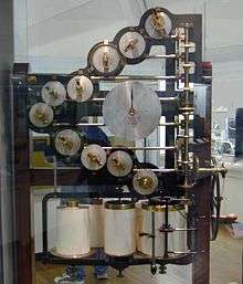
Solutions to the Fourier equation can be provided by Fourier series.[22] Ingersoll and Zobel state that in many cases the calculation involved makes the solution "well-nigh impossible" by analytical means. With modern technology such a calculation is trivially easy, but Ingersoll and Zobel recommend the use of harmonic analysers, which are the mechanical counterpart of today's spectrum analysers. These machines add together mechanical oscillations of various frequencies, phases and amplitudes by combining them through a set of pulleys or springs; one for each oscillator. The reverse process is also possible, driving the machine with the function and measuring the Fourier components as output.[23]
Background to AT&T research
After the work of John R. Carson in 1915[24] it became clear that multiplexed telephone transmissions could be greatly improved by the use of single sideband suppressed carrier (SSB) transmission. Compared to basic amplitude modulation (AM) SSB has the advantage of half the bandwidth and a fraction of the power (one sideband can have no more than 1/6 of the total power and would typically be a lot less). AM analysed in the frequency domain consists of a carrier and two sidebands. The carrier wave in AM represents the majority of the transmitted power but contains no information whatsoever. The two sidebands both contain identical information so only one is required, at least from an information transmission point of view. Up to this point filtering had been by simple tuned circuits. However, SSB required a flat response over the sideband of interest and maximum rejection of the other sideband with a very sharp transition between the two. As the idea was to put another (completely different) signal in the slot vacated by the unwanted sideband it was important that all traces of it were removed to prevent crosstalk. At the same time minimum distortion (i.e. flat response) is obviously desirable for the sideband being retained. This requirement led to a big research effort in the design of electric wave filters.[25]
| Electric wave filters |
| The term electric wave filter was much used around Zobel's time to mean a filter designed to pass or reject waves of specified frequencies across the band. It appears in numerous papers published in the early 20th century. Sometimes used to distinguish these more advanced designs from the simple tuned circuits which preceded them. In modern usage the simpler term filter would be used and is unambiguous within the field of electronics. |
George A. Campbell and Zobel worked on this problem of extracting a single sideband from an amplitude-modulated composite wave for use in multiplexing telephone channels and the related problem of extracting (de-multiplexing) the signal at the far end of the transmission.[1][2]
Initially, the baseband pass range used was 200 Hz to 2500 Hz but later the International Telecommunication Union set a standard of 300 Hz to 3.4 kHz with 4 kHz spacing. Thus the filtering was required to go from fully pass to fully stop in the space of 900 Hz. This standard in telephony is still in use today and had remained widespread until it began to be supplanted by digital techniques from the 1980s onwards.[26]
Campbell had previously utilised the condition discovered in the work of Oliver Heaviside for lossless transmission to improve the frequency response of transmission lines using lumped component inductors (loading coils). When Campbell started investigating electric wave filter design from 1910, this previous work naturally led him to filters using ladder network topology using capacitors and inductors. Low-pass, high-pass and band-pass filters were designed. Sharper cut-offs and higher stop-band rejection to any arbitrary design specification could be achieved merely by increasing the length of the ladder. The filter designs used by Campbell[27] were described by Zobel as constant k filters although this was not a term used by Campbell himself.[28]
Innovations
After Zobel arrived at the Engineering Department of AT&T he used his mathematical skills to further improve the design of electric wave filters. Carson and Zobel developed the mathematical method of analyzing the behavior of filters now known as the image method whereby the impedance and transmission parameters of each section are calculated as if it is part of an infinite chain of identical sections.[29]
Wave filters

Zobel invented the m-derived (or m-type) filter section in 1920, the distinguishing feature of this design being a pole of attenuation close to the filter cut-off frequency. The result of this design is a filter response which falls very rapidly past the cut-off frequency. To use a well known quaint engineer's expression it "goes off like the side of a house". A fast transition between pass-band and stop-band was one of the primary requirements for cramming as many telephone channels as possible into one cable.[2][30]
One disadvantage of the m-type section was that at frequencies past the pole of attenuation, the response of the filter started to increase again, reaching a peak somewhere in the stop-band and then falling again.[31] Zobel overcame this problem by designing hybrid filters using a mixture of constant k and m-type sections. This gave Zobel the advantages of both: the fast transition of the m-type and good stop-band rejection of the constant k.[32]
By 1921 Zobel had further perfected his composite filter designs. He was now using, in addition, m-type half sections at the ends of his composite filters to improve the impedance matching of the filter to the source and the load,[2] a technique in which he held a patent.[33] The difficulty that he was trying to overcome was that the image impedance techniques being used to design filter sections only gave the mathematically predicted response if they were terminated in their respective image impedances. Technically, this was easy to do within the filter as it could always be arranged that adjacent filter sections had matching image impedances (one of the characteristics of m-type sections is that one side or the other of the m-type section will have an image impedance identical to the equivalent constant k section). However, the terminating impedances are a different story. These are normally required to be resistive but the image impedance will be complex. Even worse, it is not even mathematically possible to construct a filter image impedance out of discrete components. The result of impedance mismatch is reflections and a degraded filter performance. Zobel found that a value of m=0.6[34][35] for the end half sections, while not mathematically exact, gave a good match to resistive terminations in the pass-band.[1][36]
Around 1923, Zobel's filter designs were reaching the peak of their complexity. He now had a filter section to which he had doubly applied the m-derivation process resulting in filter sections which he called the mm'-type. This had all the advantages of the previous m-type, but more so. An even faster transition into the stop-band and an even more constant characteristic impedance in the pass-band. At the same time one side would match into the old m-type, just as the m-type could match into the k-type. Because there were now two arbitrary parameters (m and m') that the filter designer could adjust, much better end matching half-sections could be designed. A composite filter using these sections would have been the very best that could have been achieved at that time. However, the mm'-type sections never became as widespread and well known as the m-type sections, possibly because their greater complexity has deterred designers. They would have been inconvenient to implement with microwave technology and the increased count of components, especially wound components, made them more expensive to implement with conventional LC technology. Certainly, it is hard to find a textbook from any period which covers their design.[37]
Transmission line simulation
Zobel directed much of his effort in the 1920s to constructing networks which could simulate transmission lines. These networks were derived from filter sections, which themselves had been derived from transmission line theory and the filters were used on transmission line signals. In turn, these artificial lines were used to develop and test better filter sections.[38][39][40] Zobel used a design technique based on his theoretical discovery that the impedance looking into the end of a filter chain was practically the same (within the limits of component tolerances) as the theoretical impedance of an infinite chain after only a small number of sections had been added to the chain. These "image" impedances have a mathematical characterization impossible to construct simply out of discrete components, and can only ever be approximated. Zobel found that using these impedances constructed out of small filter chains as components in a greater network allowed him to build realistic line simulators. These were not in any sense intended as practical filters in the field, but rather the intention was to construct good controllable line simulators without having the inconvenience of miles of cable to contend with.[41]
Equalisers
Zobel invented several filters whose defining characteristic was a constant resistance as the input impedance. The resistance remained constant through the pass band and the stop band. With these designs Zobel had completely solved the impedance matching problem. The main application of these sections has been not so much for filtering out unwanted frequencies, the k-type and m-type filters remained best for this, but rather to equalize the response in the pass band to a flat response.[42]
Perhaps one of Zobel's most fascinating inventions is the lattice filter section. This section is both constant resistance and flat response zero attenuation across the band, yet it is constructed out of inductors and capacitors. The only signal parameter it modifies is the phase of the signal at different frequencies.[43]
Impedance matching
A common theme throughout Zobel's work is the issue of impedance matching. The obvious approach to filter design is to design directly for the attenuation characteristics desired. With modern computing power, a brute force approach is possible and easy, simply incrementally adjusting each component while recalculating in an iterative process until the desired response is achieved. However, Zobel developed a more indirect line of attack. He realized very early on that mismatched impedances inevitably meant reflections, and reflections meant a loss of signal. Improving the impedance match, conversely, would automatically improve a filter's pass-band response.[37]
This impedance matching approach not only led to better filters but the techniques developed could be used to construct circuits whose sole purpose was to match together two disparate impedances.[44][45] Zobel continued to invent impedance matching networks throughout his career. During World War II he moved on to waveguide filters for use in the newly developed radar technology.[46] Little was published during the war for obvious reasons but towards the end with Bell Labs in the 1950s, Zobel designs for sections to match physically different waveguide sizes appear.[14][15] However, the circuit noted above which still bears Zobel's name today, the constant-resistance network, can be viewed as an impedance matching circuit and remains Zobel's finest achievement in this regard.[3]
Loudspeaker equalisation
The name of Zobel is, perhaps, most well known with regard to impedance compensation networks for loudspeakers. Clearly, his designs have applications in this field. However, none of Zobel's patents or articles appear to discuss this topic. It is unclear whether he actually designed anything specifically for loudspeakers. The closest we get to this is where he speaks of impedance matching into a transducer, but here he is discussing a circuit to equalize a submarine cable,[3] or in another instance where clearly he has in mind the hybrid transformer which terminates a line going into a telephone instrument on a phantom circuit.[44]
Noise
While Carson led the way theoretically, Zobel was involved in the design of filters for the purpose of noise reduction on transmission systems.[47]
Background
At the beginning of the 1920s and through to the 1930s, the thinking on noise was dominated by the radio engineers' concern with external static. In modern terminology, this would include random (thermal and shot) noise but those concepts were relatively unknown and little understood at the time despite an early paper by Schottky in 1918 on shot noise.[48] To the radio engineers of the time, static meant externally generated interference. The line of attack against noise from the radio engineers included developing directional antennae and moving to higher frequencies where the problem was known not to be so severe.[49]
For telephone engineers, what was then called "fluctuating noise", and would now be described as random noise, i.e. shot and thermal noise, was much more noticeable than with early radio systems. Carson broadened the radio engineers' concept of signal-to-static ratio to a more general signal-to-noise ratio and introduced a figure of merit for noise.[50][51]
Impossibility of noise cancellation
The radio engineers' preoccupation with static and the techniques being used to reduce it led to the idea that noise could be totally eliminated by, in some way, compensating for it or canceling it out. The culmination of this viewpoint was expressed in a 1928 paper by Edwin Armstrong.[52] This led to a famous retort by Carson in a subsequent paper, "Noise, like the poor, will always be with us".[53] Armstrong was technically in the wrong in this exchange, but in 1933, ironically and paradoxically, went on to invent wide-band FM which enormously improved the noise performance of radio by increasing the bandwidth.[54]
Carson and Zobel in 1923 had conclusively shown that filtering cannot remove noise to the same degree as, say, interference from another station could be removed. To do this they had analyzed random noise in the frequency domain and postulated that it contains all frequencies in its spectrum. This was the first use of Fourier analysis to describe random noise and hence described it in terms of a spread of frequencies. Also first published in this paper was the concept of what we would now call band-limited white noise. For Zobel this meant that characteristics of the receiving filter completely determine the figure of merit in the presence of white noise and that the filter design was key to achieving the optimum noise performance.[5]
Although this work by Carson and Zobel was very early, it was not universally accepted that noise could be analyzed in the frequency domain in this way. For this reason, the aforementioned exchange between Carson and Armstrong was still possible years later. The precise mathematical relationship between noise power and bandwidth for random noise was finally determined by Harry Nyquist in 1928 thus giving a theoretical limit to what could be achieved by filtering.[55]
This work on noise produced the concept, and led Zobel to pursue the design, of matched filters. This is the concept that the noise performance of the equipment is optimal when the filter is perfectly matched to the signal one is attempting to transmit and is the culmination of theoretical research into the application of removing noise by means of linear filters. This became important in the development of radar during the Second World War in which Zobel played a part.[56]
Use of work in genetic programming research
Zobel's work has recently found an application in research into genetic programming. The purpose of this research is to attempt to demonstrate that the results obtained from genetic programming are comparable to human achievements. Two of the measures that are used to determine whether a genetic programming result is human-competitive are:[57]
- The result is a patented invention.
- The result is equal to or better than a result that was considered an achievement in its field at the time of discovery.
One such problem set as a task for a genetic program was to design a crossover filter for woofer and tweeter loudspeakers. The output design was identical in topology to a design found in a patent of Zobel's[58] for a filter to separate multiplexed low and high frequencies on a transmission line. This was judged to be human-comparable, not only because of the patent, but also because the high-pass and low-pass sections were "decomposed" as in Zobel's design, but not specifically required to be so in the programs parameters.[57] Whether or not Zobel's filter design would be good for a hi-fi system is another question. The design does not actually cross over, but rather, there is a gap between the two pass-bands where the signal is not transmitted to either output. Essential for multiplexing, but not so desirable for sound reproduction.[59]
A later genetic programming[60] experiment produced a filter design which consisted of a chain of constant k sections terminated in an m-type half section. This was also determined to have been a design patented by Zobel.[33]
Notes
- 1 2 3 Bray, p. 62.
- 1 2 3 4 5 White, G, "The Past", BT Technology Journal, Vol 18, No 1, pp. 107–132, January 2000 doi:10.1023/A:1026506828275.
- 1 2 3 Zobel, O J, Distortion Compensator, U.S. Patent 1,701,552, filed 26 June 1924, issued 12 Feb 1929.
- ↑ Schwartz, p. 9.
- 1 2 Carson, J R and Zobel, O J, "Transient Oscillation in Electric Wave Filters", Bell System Technical Journal, vol. 2, July 1923, pp. 1–29.
- 1 2 3 4 5 6 "Dr. Otto Zobel". Oshkosh Daily Northwestern. January 12, 1970. p. 21. Retrieved November 23, 2016 – via Newspapers.com.

- ↑ Poggendorff, J C, Poggendorffs biographisch-literarisches handwörterbuch für mathematik, astronomie, physik mit geophysik, chemie, kristallographie und verwandte wissensgebiete, p.2969, Verlag Chemie, g.m.b.h. 1940
- ↑ "Student theses", Ripon College.
- ↑ "Distinguished Alumni Award Recipients", Ripon College.
- ↑ American Association for the Advancement of Science (August 1914). "Doctorates Conferred by American Universities". Science. 40 (1025): 256–64. Bibcode:1914Sci....40..256.. doi:10.1126/science.40.1025.256. PMID 17814604.
- 1 2 Leonard et al., passim
- ↑ American Telephone and Telegraph Company, The Bell System Technical Journal, p. 686, 1922
- ↑ Seising, R, The Fuzzification of Systems, 2007, Springer Berlin / Heidelberg ISBN 3-540-71794-3
- 1 2 Zobel, O J, Impedance Transformer, U.S. Patent 2,767,380, filed 30 Sept 1952, issued 16 Oct 1956.
- 1 2 Zobel, O J, Microwave Filter, U.S. Patent 2,623,120, filed 20 April 1950, issued 23 Dec 1952.
- ↑ Record of addresses given in patents
- ↑ Social Security Death Index database query through WorldVitalRecords.com
- ↑ Thomson, William, "On the Theory of the Electric Telegraph", Proceedings of the Royal Society of London, Vol 7, pp. 382–399. doi:10.1098/rspl.1854.0093
- ↑ Hunt, B J, The Maxwellians, p. 63, Cornell University Press, 2005 ISBN 0-8014-8234-8.
- ↑ Leonard et al., pp. 9–14.
- ↑ Zobel, pp. 3–4.
- ↑ Leonard et al., pp. 25–26.
- ↑ Ingersoll and Zobel, pp. 62–64.
- ↑ Carson, J R, Electric Circuit Theory and Operational Calculus, 1926, McGraw-Hill, New York.
- ↑ Bray, pp. 61,63.
- ↑ Bray, pp. 62, 64.
- ↑ Campbell, G A, "Physical Theory of the Electric Wave-Filter", Bell System Tech J, November 1922, vol 1, no 2, pp. 1–32.
- ↑ Bray, p. 53.
- ↑ Chu, W, Chung-Kwei Chang, Transients of Resistance-Terminated Dissipative Low-Pass and High-Pass Electric Wave Filters, Proceedings of the IRE, vol 26, no 10, pp. 1266–1277, October 1938
- ↑ Matthaei et al., p. 65.
- ↑ Ghosh, Smarajit, Network Theory: Analysis and Synthesis, Prentice Hall of India, pp. 564–569.
- ↑ Zobel, pp. 26–28.
- 1 2 Zobel, O J, Terminating network for filters, U.S. Patent 1,557,229, filed 30 April 1920, issued 13 Oct 1925.
- ↑ Matthaei et al., pp. 72–74.
- ↑ Redifon Radio Diary, 1970, p. 47, William Collins Sons & Co, 1969
- ↑ Shea, T E, Transmission Networks and Wave Filters, 1929, Bell Telephone Laboratories.
- 1 2 Zobel, O J, Electrical Wave Filter, U.S. Patent 1,850,146, filed 25 Nov 1930, issued 22 March 1932.
- ↑ Zobel, O J, Electrical network, U.S. Patent 1,760,973, filed 27 March 1928, issued 3 June 1930.
- ↑ Zobel, O J, Electrical Network, U.S. Patent 1,720,777, filed 9 Sept 1926, issued 16 July 1929.
- ↑ Zobel, O J, Electrical Network, U.S. Patent 1,591,073, filed 15 Dec 1922, issued 6 July 1926.
- ↑ Zobel, O J, Selective Constant-Resistance Network, U.S. Patent 1,724,987, filed 13 April 1928, issued 20 Aug 1929.
- ↑ Zobel, O J, Electrical Network and Method of Transmitting Electric Currents, U.S. Patent 1,603,305, filed 9 Aug 1922, issued 19 Oct 1926.
- ↑ Zobel, O J, Phase-shifting network, U.S. Patent 1,792,523, filed 12 March 1927, issued 17 Feb 1931.
- 1 2 Zobel, O J, Electrical Wave Filter, U.S. Patent 1,615,252, filed 9 June 1923, issued 25 Jan 1927.
- ↑ Zobel, O J, Complementary filter, U.S. Patent 1,557,230, filed 30 April 1920, issued 13 Oct 1925.
- ↑ Schwartz, pp. 7–8.
- ↑ Schwartz, pp. 5–7.
- ↑ Schottky, W, "Uber spontane Stromschwankungen in verschiedenen Elecktrizitätsleitern", Annalen der Physik, verte folge, Band 57, 1918, pp. 541–567.
- ↑ Schwartz, pp. 3–5.
- ↑ Carson, J R, "Signal-to-Static-Interference Ratio in Radio Telephony", Proceedings of the IRE, vol 11, June 1923, pp. 271–274.
- ↑ Schwartz, pp. 1, 5.
- ↑ Armstrong, E H, "Methods of Reducing the Effect of Atmospheric Disturbances", Proceedings of the IRE, vol. 16 no 1, January 1928, pp. 15–26.
- ↑ Carson, J R, "The Reduction of Atmospheric Disturbances", Proceedings of the IRE, vol 16 no 7, July 1928, pp. 966–975.
- ↑ Armstrong, A H, Radiosignaling, U.S. Patent 1,941,069, filed 24 January 1933, issued 26 December 1933
- ↑ Nyquist, H, "Thermal Agitation of Electric Charges in Conductors", Physical Review, vol. 32, July 1928, pp. 110–113. doi:10.1103/PhysRev.32.110
- ↑ Schwartz, p. 7.
- 1 2 Koza, Bennet; Andre, Keane (1999). Genetic Programming III: Darwinian Invention and Problem Solving. San Francisco: Morgan Kaufmann.
- ↑ Zobel, O J, Wave Filter, U.S. Patent 1,538,964, filed 15 Jan 1921, issued 26 May 1925.
- ↑ Zobel's U.S. Patent 1,538,964 (p.4, l.23) enumerates the gap as 400 Hz
- ↑ Chakrabarti, A, Engineering Design Synthesis: Understanding, Approaches, and Tools, p. 328, Springer, 2002.
References
- Bray, J, Innovation and the Communications Revolution, Institution of Electrical Engineers, 2002 ISBN 0-85296-218-5.
- Leonard, R, Zobel, O J, Ingersoll, A C, An Introduction to the Mathematical Theory of Heat Conduction with Engineering and Geological Applications, 1913, Ginn and Co, Boston, New York.
- Matthaei, G L; Young, L; Jones, E M T, Microwave Filters, Impedance-Matching Networks, and Coupling Structures McGraw-Hill 1964 (1980 edition is ISBN 0-89006-099-1).
- Schwartz, M, "Improving the Noise Performance of Communication Systems: 1920s to early 1930s", Technologies, Technologists & Networks: A Symposium on the History of Communication Technologies, October 17, 2007, Smithsonian National Postal Museum.
- Zobel, O J,Theory and Design of Uniform and Composite Electric Wave Filters, Bell System Technical Journal, Vol. 2 (1923), pp. 1–46.