Object Process Methodology
Object Process Methodology (OPM) is a conceptual modeling language and methodology for capturing knowledge and designing systems, specified as ISO 19450. Based on a minimal universal ontology of stateful objects and processes that transform them, OPM formally specifies the function, structure, and behavior of artificial and natural systems in a large variety of domains. Catering to human cognitive principles, an OPM model represents the system under design or study bimodally in both graphics and text for improved representation, understanding, communication, and learning.
OPM was conceived and developed by Prof. Dov Dori at the Technion – Israel Institute of Technology and at Massachusetts Institute of Technology. The first paper,[1] in which ideas underlying OPM were presented for the first time, was published in 1995. Since then, OPM has evolved and developed. In 2002, the first book on OPM[2] was published, and on December 15, 2015, after six years of work by ISO TC184/SC5, ISO adopted OPM as ISO 19450 Publicly Available Specification – Automation systems and integration - Object-Process Methodology. A second book[3] is being published in 2016.
OPM is bimodal – it is expressed both visually-graphically and verbally-textually. A set of one or more diagrams of a single kind, called Object-Process Diagram (OPD), is the visual expression, and a corresponding set of automatically-generated sentences in a subset of English, called Object-Process Language (OPL), is the verbal expression. A freely available software package, OPCAT, is downloadable from Technion's Enterprise Systems Modeling Laboratory.
The elements in an OPD are things – objects and processes – and links that connect the things to express relations among them. An OPM object is a thing that exists, or might exist, physically or informatically. Objects are stateful – they may have states, such that at each point in time, the object is at one of its states or in transition between states. An OPM process is a thing that transforms an object by creating or consuming it, or by changing its state.
Graphical Contents


History of OPM
The shift to the object oriented (OO) paradigm for programming languages, which occurred in the 1980s and 1990s, was followed by the idea that programming should be preceded by analysis and design of the programs, or, more generally, the systems those programs represent and serve. Inspired by OO languages, the approach taken as the basis for analysis was also object-oriented. Thus, in the early 1990', over 30 object-oriented analysis and design methods and notations flourished, leading to what was known as the "Methods War" (Booch, 1993).[4]
Around that time, in 1991, Prof. Dov Dori, who then joined Technion, Israel Institute of Technology as faculty, realized that just as the procedural approach to software was not necessarily the most adequate one, so was the "pure" OO approach, which puts objects as the sole "first class" citizens, with "methods" (or "services", or "operations") being their second-class subordinate procedures. When he and colleagues from University of Washington were trying to model a system for automated transforming of engineering drawings to CAD models, he realized that not all the boxes in their model were really objects; some were things that happen to objects. When he circled those things, a bipartite graph emerged, in which the nodes representing objects—the things that exist—were mediated by those circled nodes, which were identified as processes—the things that transform the objects.
The first paper on OPM[1] was published in 1995.
In 1997, the "Methods Wars" culminated in the adoption of the Unified Modeling Language (UML), by Object Management Group (OMG), making it the de facto standard for software design.UML 1.1 was submitted to the OMG in August 1997 and adopted by the OMG in November 1997.
UML 1.X had nine types of diagrams. Following a 2001 initiative of the International Council on Systems Engineering (INCOSE), in 2003 OMG issued the UML for Systems Engineering Request for Proposals, and in 2006 OMG adopted SysML (Systems Modeling Language) 1.0 specification, which is based on UML 2. Since then, SysML has become the de facto standard for systems engineering.
The first book on OPM, Object-Process Methodology – a Holistic Systems Paradigm (Dori, 2002),[5] was published in 2002, and OPM has since been successfully applied and papers published in many diverse domains, ranging from the Semantic Web to defense and to molecular biology The realization and recognition that models can and should become the central artifact in system lifecycles has been gaining momentum in recent years, giving rise to model-based systems engineering (MBSE) as an evolving filed in the area of systems engineering. In August 2014, after five years of work by ISO TC184/SC5, ISO adopted OPM as ISO 19450 – Automation systems and integration – Object-Process Methodology.
Currently under publication in both paper and electronic versions is the second book on OPM, which also covers SysML, titled Model-Based Systems Engineering with OPM and SysML (Dori, 2016).[6] SysML and OPM have been serving as the two MBSE languages, but since SysML was adopted as a standard about eight years before OPM and has been backed by top-notch vendors, its adoption is currently more widespread. However, OPM is rapidly gaining acceptance in academia and industry.
Versions
- OPM Versions

The current version of OPM is ISO/PAS 19450:2015 as specified in Automation Systems and Integration — Object-Process Methodology.[7] The specification in the book[3] is a superset of ISO/PAS 19450:2015.
The previous version of OPM was specified in the book.[2]
- OPCAT Versions
The current OPCAT version is 4.1. It is available freely from Technion's Enterprise Systems Modeling Laboratory.[8]
A previous OPCAT version, 3.1, with fewer capabilities, is also available from the same site. Both are coded in Java. The first OPCAT version, OPCAT 1.X, was written in Visual C++ in 1998.
In the beginning of the year 2016 a team of Students in the Technion under the management of Prof. Dov Dori, has begun working on the new generation of OPCAT which will be called OPCloud. As suggested by the name of the software it will be a cloud based application, and will enable users to create OPM models using a web based application. (Demo)
Design
Object-Process Methodology (OPM) is a systems modeling paradigm that represents the two aspects inherent in any system: its structure and its behavior. Structure is represented via objects and structural relations among them, such as aggregation-participation (whole-part relation) and generalization-specialization ("is-a" relation). Behavior is represented by processes and how they transform objects: How they create or consume objects, or how they change the states of an object. Indeed, OPM is fundamentally simple; it builds on a minimal set of concepts: stateful objects – things that exist or might exist physically or informatically at some state, and processes – things that happen to objects and transform them by creating or consuming the objects or by changing their states.[9] OPM offers a way to model systems of almost any domain, be it artificial or natural. OPM is founded on a universal minimal ontology, according to which objects exist, while processes transform them. Transformation includes object creation and consumption, as well as change of the state of an object. Hence, stateful objects and processes that transform them are the only two concepts in OPM's universal minimal ontology. Two other cornerstones of OPM are its bi-modal graphical-textual representation and its built-in refinement-abstraction complexity management mechanisms of in-zooming and unfolding of a single type of diagram—Object-Process Diagram (OPD).
Modeling
OPM represents the system model simultaneously in two different modalities: formal graphics – Object Process Diagramׂ (OPD) and a corresponding set of sentences in a subset of English, called Object Process Language (OPL). OPL is generated automatically by OPCAT,[10] downloadable from[11] - a software tool that supports modeling in OPM.
- Object Process Diagramׂ (OPD)
OPD is the one and only kind of diagram of OPM. This uniqueness of diagram kind is a major contributor to OPM's simplicity, and it is in sharp contrast to UML, which has 14 kinds of diagrams, and to SysML, which has nine such kinds. An OPD graphically describes objects, processes and links among them. Links can be structural and procedural. Structural links connect objects to objects or processes to processes, expressing the static system aspect - how the system is structured. Procedural links connect objects to processes, expressing the dynamic system aspect – how the system changes over time. The entire system is represented by a set of hierarchically-organized OPDs, such that the root OPD, called the systems diagram (SD), specifies the "bird's eye" view of the system, and lower-level OPDs specify the system in increasing levels of detail. All the OPDs in the system's OPD set are "aware" of each other, with each showing the system, or part of it, at some level of detail. The entire system is specified in its entirety by the union of the details model facts) appearing in all the OPDs.
- Object Process Language(OPL)
Each OPD construct (i.e., two or more things connected by one or more link) is translated to a sentence in OPL – a subset of natural English. The power of OPL lies in the fact that it is readable by humans but also interpretable by computers. Since each model fact is expressed both graphically and textually, in a subset of natural English, it is readily accessible to non-technical stakeholders, enabling them to take part in the early, critical stages of the system requirements elicitation, architecting and development. These are the stages where the most important design decisions are made. The graphics-text bimodality of OPM makes it suitable to jointly model requirements by a team that involves both the customer or his domain expert on one hand, and the system architect, modelers, and designers on the other hand.[12]
- OPM Model Animated Simulation
OPM models are not just static graphical and textual representations of the system—they are also executable. A correct OPM model constructed in OPCAT can be simulated by animating it, visually expressing how the system behaves over time to achieve its function at all detail levels. An incorrect OPM model will not execute all the way through, and will indicate where and why it is stuck, effectively serving as a visual debugger.
OPM Development
OPM semantics was originally geared towards systems engineering, as it can model information, hardware, people, and regulation. However, in recent years OPM started to serve also researchers in molecular biology, yielding tangible published new findings related to the mRNA lifecycle.[13] This is a clear indication of the universality of the object and process ontology.[12]
OPM Basics

Object-Process Methodology has two main parts: The language and the methodology. The language is bimodal—it is expressed in two complementary ways (modalities): the visual, graphical part—a set of one or more Object-Process Diagrams (OPDs), and a corresponding textual part—a set of sentences in Object-Process Language (OPL), which is a subset of English. The top-level OPD is the system diagram (SD), which provides the context for the system's function. For man-made systems this function is expected to benefit a person or a group of people—the beneficiary. The function is the main process in SD, which also contains the objects involved in this process: the beneficiary, the operand (the object upon which the process operates), and possibly the attribute whose value the process changes.
OPM graphical elements are divided into entities, expressed as closed shapes, and relations, expressed as links that connect entities.
OPM Entities: Objects, Processes, and Object States
Entities are the building blocks of OPM. They include objects and processes, collectively called things, and object states.
- Object: An object is a thing, which once constructed, exists or can exist physically or informatically. Associations among objects constitute the object structure of the system being modeled. In OPL text, the object name shall appear in bold face with capitalization of each word.
- Object State: An object state is a particular situation classification of an object at some point during its lifetime. At every point in time, the object is in one of its states or in transition between two of its states - from its input state to its output state.
- Process: A process is an expression of the pattern of transformation of objects in the system. A process does not exist in isolation; it is always associated with and occurs or happens to one or more objects. A process transforms objects by creating them, consuming them, or changing their state. Thus, processes complement objects by providing the dynamic, behavioral aspect of the system. In OPL text, the process name shall appear in bold face with capitalization of each word.
 OPM Structural Links
OPM Links
Structural and Procedural Links
- Structural link: A structural links defines a structural relation. A structural relation shall specify an association that persists in the system for at least some interval of time.
- Procedural link: A procedural link defines procedural relation. A procedural relation shall specify how the system operates to attain its function, designating time dependent or conditional triggering of processes, which transform objects.
Event and Condition Links

The Event-Condition-Action paradigm provides the OPM operational semantics and flow of control. An event is a point in time at which an object is created (or appears to be created from the system's perspective) or an object enters a specified state. At runtime, this process triggering initiates evaluation of the process precondition. Thus, starting a process execution has two prerequisites: (1) a triggering event, and (2) satisfaction of a precondition. Once the event triggers a process, the event ceases to exist. The precondition is the existence of the required object instances in the preprocess object set, possibly in specific states, as modeled. If and only if the evaluation reveals satisfaction of the precondition, the process starts executing.
OPM Modeling Language and Diagram: Syntax and Semantics
OPM Things
- OPM thing definition: An OPM thing is a generalization of object and process. Objects and processes are symmetric in many regards and have much in common in terms of relations, such as aggregation, generalization, and characterization. OPM objects and OPM processes depend on each other in the sense that an object cannot be transformed without a process, while a process cannot happen without transforming at least one object.
To apply OPM in a useful manner, the modeler has to make the essential distinction between objects and processes, as a prerequisite for successful system analysis and design. By default, a noun shall identify an object.
- OPM thing generic attributes: OPM things have the following three generic attributes:
- Perseverance, which pertains to the thing’s persistence and determines whether the thing is static, i.e., an object, or dynamic, i.e., a process.
- Essence, which pertains to the thing’s nature and determines whether the thing is physical or informatical. Accordingly, the values of the generic attribute Essence are physical and informatical.
- Affiliation, which pertains to the thing’s scope and determines whether the thing is systemic, i.e., part of the system, or environmental, i.e., part of the system’s environment. Accordingly, the values of the generic attribute Affiliation are systemic and environmental. Graphically shading effects shall depict physical OPM things and dashed lines shall depict environmental OPM things.
- Default values of generic attributes
- The default value of the Affiliation generic attribute of a thing is systemic.
- System essence shall be the primary essence of the system. Like thing essence, its values are informatical and physical. Information systems, in which the majority of things are informatical, shall be primarily informatical, while systems in which the majority of things are physical shall be primarily physical.
- The default value of the Essence generic attribute of a thing in a primarily informatical [physical] system shall be informatical [physical].

Object States
- Stateful and stateless objects: Object state is a possible situation in which an object may exist. An object state has meaning only in the context of the object to which it belongs. A stateless object shall be an object that has no specification of states. A stateful object shall be an object for which a set of permissible states are specified. In a runtime model, at any point in time, any stateful object instance is at a particular permissible state or in transition between two states.
- Attribute values: Attribute is an object that characterizes a thing. An attribute value is a specialization of state in the sense that a value is a state of an attribute: an object has an attribute, which is a different object, to which that value is assigned for some period of time during the existence of the object exhibiting that attribute.
- Object state representation: A process is graphically defined by a labelled, rounded-corner rectangle placed inside the owning object. In OPL text, the process name shall appear in bold face without capitalization.
- Initial, default, and final states: The initial state of an object is its state as the system starts executing or its state upon generation by the system during execution. The final state of an object is its state as the system completes executing or its state upon consumption by the system during execution. The default state of an object is its expected state—the state in which the object is most likely to be when randomly inspected. An object can have zero or more initial states, zero or more final states, and zero or one default state.
- Initial, final, and default state representation: A state that is initial is graphically defined by a state representation with thick contour. A state that is final is graphically defined by a state representation with double contour. A state that is default is graphically defined by a state representation with an open arrow pointing diagonally from the left. The corresponding OPL sentences shall include explicit indicators for an initial, final or default state.
OPM Links
Procedural Links
A procedural link is one of three kinds:
- Transforming link, which connects a transformee (an object that the process transforms) or its state with a process to model object transformation, namely generation, consumption, or state change of that object as a result of the process execution.
- Enabling link, which connects an enabler (an object that enables the process occurrence but is not transformed by that process) or its state, to a process, which enables the occurrence of that process.
- Control link, which is a procedural (transforming or enabling) link with a control modifier – the letter e (for event) or c (for condition), which adds semantics of a control element. The letter e signifies an event for triggering the linked process, while the letter c signifies a condition for execution of the linked process, or connection of two processes denoting invocation, or exception.
- Procedural link uniqueness OPM principle: A process needs to transform at least one object. Hence, a process shall be connected via a transforming link to at least one object or object state. At any particular extent of abstraction, an object or any one of its states shall have exactly one role as a model element with respect to a process to which it links: the object may be a transformee or an enabler. Additionally, it can a trigger for en event (if it has the control modifier e), or a conditioning object (if it has the control modifier c), or both. According to the procedural link uniqueness OPM principle, at a given extent of abstraction, an object or an object state shall link to a process by only one procedural link.
- State-specified procedural links: Each procedural link may be qualified as state-specified procedural links. A state-specified procedural link is a detailed version of its procedural link counterpart in that rather than connecting a process to an object, it connects a process to a specific state of that object.
 OPM Enabling Links
 - Transforming links: A transforming link specifies a connection between a process and its transformee (the object it creates, consumes, or changes the object state). The three kinds of transforming links is:
- Consumption link: A transforming link specifying that the linked process consumes (destroys, eliminates) the linked object, the consumee. Existence of the consumee is precondition (or part of the precondition) to the activation of the process. Graphically, an arrow with a closed arrowhead pointing from the consumee to the consuming process defines the consumption link. By assumption, the consumed object disappears as soon as the process begins execution. The syntax of a consumption link OPL sentence is: Processing consumes Consumee.
- Effect link: An transforming link specifying that the linked process affects the linked object, which is the affectee, i.e., the process causes some unspecified change in the state of the affectee. Graphically, a bidirectional arrow with two closed arrowheads, one pointing in each direction between the affecting process and the affected object, shall define the effect link. The syntax of an effect link OPL sentence is: Processing affects Affectee.
- Result link: A transforming link specifying that the linked process creates (generates, yields) the linked object, which is the resultee. Graphically, an arrow with a closed arrowhead pointing from the creating process to the resultee shall define a result link. The syntax of a result link OPL sentence is: Processing yields Resultee.
- Enabling links: An enabling link is a procedural link specifying an enabler for a process - an object that must be present for that process to occur, but the existence and state of that object after the process is complete are the same as just before the process began. The two kinds of enabling links is:
- Agent and Agent Link: A human or a group of humans capable of intelligent decision-making, who enable a process by interacting with the system to enable or control the process throughout execution. It is an enabling link specifying that the agent object is necessary for the linked process to execute. Graphically, a line with a filled circle ("black lollipop") at the terminal end extending from the agent object to the process it enables defines an agent link. The syntax of an agent link OPL sentence is: Agent handles Processing.
- Instrument and Instrument Link: An inanimate or otherwise non-decision-making enabler of a process that cannot start or take place without the existence and availability of the instrument. It is an enabling link specifying that the instrument object is necessary for the linked process to execute. Graphically, a line with an open circle ("white lollipop") at the terminal end extending from the instrument object to the process it enables defines an instrument link. The syntax of an instrument link OPL sentence is: Processing requires Instrument.
- State-specified transforming links
- State-specified consumption link: A consumption link that originates from a particular state of the consumee, meaning that the consumee must be in that state for it to be consumed by the process to which it is linked. Graphically, an arrow with a closed arrowhead pointing from the particular object state to the process, which consumes the object, defines the state-specified consumption link. The syntax OPL sentence is: Process consumes qualified-state Object.
- State-specified result link: A result link that terminates at a specific state of the resultee, meaning that the resultee shall be in that resultant state upon its construction. Graphically, an arrow with a closed arrowhead pointing from the process to the particular object state defines the state-specified result link. The syntax OPL sentence is: Process yields qualified-state Object.
- State-specified effect links:
- Input and output effect links- An input link is the link from the object's input state to the transforming process, while the output link is the link from the transforming process to the object's output state.
- Input-output-specified effect link- A pair of effect links, where the input link originates from a particular state of the affectee and the output link originates from that process and terminates at the output state of the same affectee. Graphically, a pair of arrows with a closed arrowhead from the input state of the affectee to the affecting process and a similar arrow from that process to the state of the affectee at process terminates defines the input-output-specified effect link. The syntax OPL sentence is: Process changes Object from input-state to output-state.
- Input-specified effect link- A pair of effect links, where the input link originates from a particular state of the affectee and the output link originates from that process and terminates at the affectee without specifying a particular state. Graphically, a pair of arrows consisting of an arrow with a closed arrowhead from a particular state—the input state—of the affectee to the process, and a similar arrow from that process to the affectee but not to any one of its states defines the input-specified effect link. The syntax OPL sentence is: Process changes Object from input-state.
- Output-specified effect link- A pair of effect links, where the input (source) link originates from an affectee, and the output link originates from the process and terminates at the output (destination, resultant) state of the same affectee. Graphically, a pair of arrows consisting of an arrow with a closed arrowhead from the affectee, but not from any one of its states, to the affecting process, and a similar arrow from that process to a particular state of that affectee— the output state— defines the output-specified effect link. The syntax OPL sentence is: Process changes Object to output-state.
- State-specified enabling links: Originate from a specific qualifying state and terminate at a process, meaning that the process may occur if and only if the object exists at the state from which the link originates.
- State-specified agent link: Aan agent link that originates from a specific qualifying state of the agent. Graphically, a line with a filled circle ("black lollipop") at the terminal end extending from the qualifying state of the agent object to the process it enables defines a state-specified agent link. The syntax OPL sentence is: Qualifying-state Agent handles Processing.
 OPM Basic Transforming Event Links
 - State-specified instrument link: An instrument link that originates from a specific qualifying state of the instrument. Graphically, a line with an empty circle ("white lollipop") at the terminal end extending from the qualifying state of the instrument object to the process it enables defines a state-specified instrument link. The syntax OPL sentence is: Processing requires qualifying-state Instrument.
The Event-Condition-Action Control
- Preprocess object set and process precondition: In order for an OPM process to start executing once it has been triggered, it needs a set of objects comprising one or more consumes, some possibly at specific states, and/or affects, collectively called the preprocess object set. The pre-process object set determines the precondition that must be satisfied before execution of that process starts and as a condition for that process to start executing. At instance-level execution, each consume B in the pre-process object set of process P shall be consumed and stop to exist at the beginning of the lowest level sub-process of P which consumes B. Each affected (an object whose state changes) B in the preprocess object set of process P shall exit from its input state at the beginning of the lowest level sub-process of P.

- Post-process object set and process post-condition: A set of objects, comprising one or more results, some possibly at given states, and/or affects, collectively called the post-process object set, shall result from executing a process and carrying out the transformations associated with its execution. The post-process object set shall determine the post-condition, which shall be satisfied after execution of that process ends. Each resulted B in the post process object set of process P shall be created and start to exist at the end of the lowest level sub process of P which yields B. Each affected B in the post-process object set of process P shall enter its output state at the end of the lowest level sub-process of P.
Control Links
An event link and a condition link express an event and a condition, respectively. Control links occur either between an object and a process or between two processes.
- Event links
Event link specifies a source event and a destination process to activate on event occurrence. Triggering a process initiates an attempt to execute the process, but it does not guarantee success of this attempt. The triggering event forces an evaluation of the process' precondition for satisfaction, which, if and only if satisfied, allows process execution to proceed and the process becomes active. Regardless of whether the precondition is satisfied or not, the event will be lost. If the precondition is not satisfied, process execution will not occur until another event activates the process and a successful precondition evaluation allows the process to execute.
- Basic transforming event links: A consumption event link is a link between an object and a process, which an instance of the object activates. Satisfaction of the process precondition and the subsequent process execution need to consume (affect) the instance of the activating object.
 OPM State-Specified Transforming Event Links
- Consumption event link- Graphically, an arrow with a closed arrowhead pointing from the object to the process with the small letter e (for event). The syntax of a consumption event link OPL sentence is: Object triggers Process, which consumes Object.
- Effect event link- Graphically, a bidirectional arrow with closed arrowheads at each end between the object and the process with a small letter e (for event). The syntax of an effect event link OPL sentence is: Object triggers Process, which affects Object.
- Basic Enabling event links:
 OPM State-Specified Agent Event Link
 OPM Invocation Links
- Agent event link- An agent event link is an enabling link from an agent object to the process that it activates and enables. Graphically, a line with a filled circle ("black lollipop") at the terminal end extending from an agent object to the process it activates and enables with a small letter e (for event). The syntax of an agent event link OPL sentence is: Agent triggers and handles Process.
- Instrument event link- An instrument event link is an enabling link from an instrument object to the process that it activates and enables. Graphically, a line with an empty circle ("white lollipop') at the terminal end extending from the instrument object to the process it activates and enables with a small letter e (for event). The syntax of an instrument event link OPL sentence is: Instrument triggers Process, which requires Instrument.
- State-specified transforming event links:
- State-specified consumption event link- A state-specified consumption event link is a consumption link that originates from a specific state of an object and terminates at a process, which an instance of the object activates. Satisfaction of the process precondition, including the activating object instance being at its specified state, and the subsequent process execution consume the activating object instance. Graphically, an arrow with a closed arrowhead pointing from the object state to the process with the small letter e (for event). The syntax of a state-specified consumption event link OPL sentence is: Specified-state Object triggers Process, which consumes Object.
- Input-output-specified effect event link- An input-output-specified effect event link is an input-output-specified effect link with the additional meaning of activating the affecting process when the object enters the specified input state. Graphically, the input-output-specified effect link with a small letter e (for event). The syntax of an input-output specified effect event link OPL sentence is: Input-state Object triggers Process, which changes Object from input-state to output-state.
- Input-specified effect event link- An input-specified effect event link is an input-specified effect link with the additional meaning of activating the affecting process when the object enters the specified input state. Graphically, the input-specified effect link with a small letter e (for event. The syntax of an input-specified effect event link OPL sentence is: Input-state Object triggers Process, which changes Object from input-state.
- Output-specified effect event link- An output-specified effect event link is an output-specified effect link with the additional meaning of activating the affecting process when the object comes into existence. Graphically, the output-specified effect link with a small letter e (for event). The syntax of an output-specified effect event link OPL sentence is: Object in any state triggers Process, which changes Object to destination-state
- State-specified agent event link:
- State-specified agent event link- A state-specified agent event link is a state-specified agent link with the additional meaning of activating the process when the agent enters the specified state. Graphically, the state-specified agent link with a small letter e (for event). The syntax of a state-specified agent event link OPL sentence is: Qualifying-state Agent triggers and handles Processing".
- State-specified instrument event link- A state-specified instrument event link is a state-specified instrument link with the additional meaning of activating the process when the instrument enters the specified state. Graphically, the state-specified instrument link with a small letter e (for event). The syntax of a state-specified instrument event link OPL sentence is: Qualifying-state Instrument triggers Processing, which requires qualifying-state Instrument."
- Invocation links
- Process invocation: Process invocation is an event of triggering of a process by a process. An invocation link is a link from an invoking process to the process that it invokes (triggers), meaning that when the invoking process terminates, it immediately triggers the process at the other end of the invocation link. Graphically, a lightening symbol jagged line from the invoking process terminating with a closed arrowhead at the invoked process end denote an invocation link. The syntax of an invocation link OPL sentence is: Invoking-process invokes invoked-process.
- Self-invocation link: Self-invocation is invocation of a process by itself, such that that upon process termination, the process immediately invokes itself. The self-invocation link shall denote self-invocation. Graphically, a pair of invocation links, originating at the process and joining head to tail before terminating back at the original process denote the self-invocation link. The syntax of a self-invocation link OPL sentence is: Invoking-process invokes itself.
- Implicit invocation link: Implicit invocation occurs upon sub-process termination within the context of an in-zoomed process, at which time the sub-process invokes the one(s) immediately below it. Graphically, there is no link between the invoking and the invoked sub-processes; their relative heights within the in-zoom context of their ancestor process implies this semantics.
- Condition links: A condition link is a procedural link between a source object or object state and a destination process that provides a bypass mechanism, which enables system control to skip the destination process if its precondition satisfaction evaluation fails, otherwise the process waits for the precondition to become true.
- Condition consumption link: A condition consumption link is a condition link from an object to a process, meaning that if in run-time an object instance exists, then the process precondition is satisfied, the process executes and consumes the object instance. However, if that object instance does not exist, then the process precondition evaluation fails and the control skips the process. Graphically, an arrow with a closed arrowhead pointing from the object to the process with the small letter c (for condition) near the arrowhead shall denote a condition consumption link. The syntax of the condition consumption link OPL sentence is: Process occurs if Object exists, in which case Object is consumed, otherwise Process is skipped.
- Condition effect link: A condition effect link is a condition link between an object and a process, meaning that if at run-time an object instance exists, and the rest of the process precondition is satisfied, then the process executes and affects the object instance. However, if that object instance does not exist, then the process precondition evaluation fails and the control skips the process. Graphically, a bidirectional arrow with two closed arrowheads, one pointing in each direction between the affected object and the affecting process, with the small letter c (for condition) near the process end of the arrow. The syntax of the condition effect link OPL sentence is: Process occurs if Object exists, in which case Process affects Object, otherwise Process is skipped.
- Condition agent link: A condition agent link is a condition link from an object to a process, meaning that if at run-time an agent instance exists and the rest of the process precondition is satisfied, then the process executes and the agent handles execution. However, if that agent instance does not exist, then the process precondition evaluation fails and the control skips the process. Graphically, a line with a filled circle ('black lollipop") at the terminal end extending from an agent object to the process it enables, with the small letter c (for condition) near the process end. The syntax of the condition agent link OPL sentence is: Agent handles Process if Agent exists, else Process is skipped.
 OPM Basic Condition Enabling Link
 - Condition instrument link: A condition instrument link is a condition link from an object to a process, meaning that if at run-time an instrument instance exists and the rest of the process precondition is satisfied, then the process executes. However, if that instrument instance does not exist, then the process precondition evaluation fails and the control skips the process. Graphically, a line with an empty circle ("white lollipop") at the terminal end, extending from an instrument object to the process it enables, with the small letter c (for condition) near the process end, shall denote a condition instrument link. The syntax of the condition instrument link OPL sentence shall be: Process occurs if Instrument exists, else Process is skipped.
- Condition state-specified consumption link: A condition state-specified consumption link is a condition consumption link that originates from a specified state of an object and terminates at a process, meaning that if an object instance exists in the specified state and the rest of the process precondition is satisfied, then the process executes and consumes the object instance. However, if that object instance does not exist in the specified state, then the process precondition evaluation fails and the control skips the process. Graphically, an arrow with a closed arrowhead pointing from the object qualifying state to the process with the small letter c (for condition) near the arrowhead.
- Condition input-output-specified effect link: A condition input-output-specified effect link is an input-output specified effect link with the additional meaning that if at run-time an object instance exists and it is in the process input state (and assuming that the rest of the process precondition is satisfied), then the process executes and affects the object instance. The effect is changing the object instance state from its input state to its output state (the state that the arrowhead of the link from the process points to). However, if that object instance does not exist at the input state, then the process precondition evaluation fails and the control skips the process. Graphically, the condition input-output-specified effect link with the small letter c (for condition) near the arrowhead of the input. The syntax of the condition input-output-specified effect link OPL sentence is: Process occurs if Object is input-state, in which case Process changes Object from input-state to output-state, otherwise Process is skipped.
- Condition input-specified effect link: A condition input specified effect link is an input-specified effect link with the additional meaning that if at run-time an object instance exists in the specified input state and the rest of the process precondition is satisfied, then the process executes and affects the object instance by changing its state from its input state to an unspecified state. However, if that object instance does not exist at the input state, then the process precondition evaluation fails and the control skips the process. Graphically, the condition input-specified effect link with the small letter c (for condition) near the arrowhead of the input link. The syntax of a condition input-specified effect link OPL sentence is: Process occurs if Object is input state, in which case Process changes Object from input-state, otherwise Process is skipped.
- Condition output-specified effect link: A condition output-specified effect link is an output-specified effect link with the additional meaning that if at run-time an object instance exists and the rest of the process precondition is satisfied, then the process executes and affects the object instance by changing its state to the specified output-state. However, if that object instance does not exist, then the process precondition evaluation fails and the control skips the process. Graphically, the condition output-specified effect link with the small letter c (for condition) near the arrowhead of the input link. The syntax of the condition output-specified effect OPL sentence is: Process occurs if Object exists, in which case Process changes Object to output-state, otherwise Process is skipped.
- Condition state-specified agent link: A condition state specified agent link is a state-specified agent link from a specified state of an object to a process, meaning that if at run-time an object instance exists in that state and the rest of the process precondition is satisfied, then the process executes and the agent handles execution. However, if an agent instance does not exist in that state, then the process precondition evaluation fails and the control skips the process. Graphically, the condition agent link extending from a specified agent state to the process it enables. The syntax of the condition state-specified agent link OPL sentence is: Agent handles Process if Agent is qualifying-state, else Process is skipped.
- Condition state-specified instrument link: A condition state-specified instrument link is a state-specified instrument link from a specified state of an object to a process, meaning that if at runtime an object instance exists in that state and the process precondition is satisfied, then the process is executes. However, if an instrument instance does not exist in that state, then the process precondition evaluation fails and the control skips the process. If the skipped process is within an in-zoom context and there is a subsequent process in this context, control triggers that process, otherwise control transfers one level up to the in-zoomed process. Graphically, the condition instrument link extending from a specified instrument state to the process it enables. The syntax of the condition state-specified instrument link OPL sentence is: Process occurs if Instrument is qualifying-state, otherwise Process is skipped.
More information and examples can be found in [Dori, 2016] Chapter 5 “More on System's Dynamics”.
Structural Links
Structural links specify static, time-independent, long-lasting relations in the system. A structural link connect two or more objects or two or more processes, but not an object and a process, except in the case of an exhibition-characterization link (add link).
- Unidirectional tagged structural link - Has a user-defined semantics regarding the nature of the relation from one thing to the other. Graphically, an arrow with an open arrowhead. Along the tagged structural link, the modeler should record a meaningful tag in the form of a textual phrase that expresses the nature of the structural relation between the connected objects (or processes) and makes sense when placed in the OPL sentence whose syntax follows.
- Unidirectional null-tagged structural link - An unidirectional tagged structural link with no tag. In this case, the default unidirectional tag is used. The modeler has the option of setting the default unidirectional tag for a specific system or a set of systems. If no default is defined, the default tag is "relates to".
- Bidirectional tagged structural link - When the tags in both directions are meaningful and not just the inverse of each other, they may be recorded by two tags on either side of a single bidirectional tagged structural link. Each tag shall align on the side of the arrow with the harpoon edge sticking out of the arrowhead unambiguously determining the direction in which each relation applies. The syntax of the resulting tagged structural link is two separate tagged structural link OPL sentences, one for each direction. Graphically, a line with harpoon shaped arrowheads on opposite sides at both ends of the link's line shall.
- Reciprocal tagged structural link - A reciprocal tagged structural link is a bidirectional tagged structural link with no more than one tag. In either case, reciprocity indicate that the tag of a bidirectional structural link has the same semantics for its forward and backward directions. When no tag appears, the default tag shall be "are related". The syntax of the reciprocal tagged structural link with only one tag shall be: Source-thing and destination thing are reciprocity-tag. The syntax of the reciprocal tagged structural link with no tag is: Source thing and Destination-thing are related.
- Fundamental structural relations - The most prevalent structural relations among OPM things and are of particular significance for specifying and understanding systems. Each of the fundamental relations is elaborate or refine one OPM thing, the source thing, or refinee, into a collection of one or more OPM things, the destination thing or things, or refineables. The fundamental structural relations are; Aggregation, Exhibition-characterization, Generalization-specialization, and Classification-instantiation.
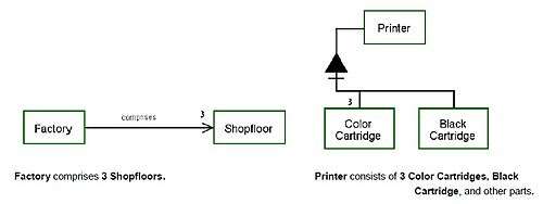
- Aggregation-participation link - Mean that a refinee—the whole—aggregates one or more other refineables—the parts. Graphically, a black solid (filled in) triangle with its apex connecting by a line to the whole and the parts connecting by lines to the opposite horizontal base shall denote the aggregation-participation relation link.
- Exhibition-Characterization link - Mean that a thing exhibits, or is characterized by, another thing. The exhibition-characterization relation binds a refinee—the exhibitor—with one or more refineables, which shall identify features that characterize the exhibitor Graphically, a smaller black triangle inside a larger empty triangle with that larger triangle's apex connecting by a line to the exhibitor and the features connecting to the opposite (horizontal) base defines the exhibition-characterization relation link.
- Generalization-Specialization and Inheritance
- Generalization-Specialization link: mean that the refinee—the general—generalizes the refineables, which are specializations of the general. Binds one or more specializations with the same persistence attribute value as the general, such that either the general and all its specializations are objects or the general and all its specializations are processes. Graphically, an empty triangle with its apex connecting by a line to the general and the specializations connecting by lines to the opposite base defines the generalization-specialization link.
- Inheritance through specialization: Inheritance is assignment of OPM elements of a general to its specializations. A specialization inherits from the general thing through the generalization-specialization link the following four kinds of inheritable elements, if there are any: 1. all the general's parts from its aggregation-participation link; 2. all the general's features from its exhibition-characterization link; 3. all the tagged structural links to which the general connects; and 4. all the procedural links to which the general connects.
 OPM Condition State-Specified Enabling Link
 - Specialization restriction through discriminating attribute:A subset of the possible values of an inherited attribute may restrict the specialization. An attribute whose different values determine corresponding specializations is a discriminating attribute
 OPM Fundamental Structural Relations and Links
- Classification-Instantiation and System Execution
- Classification-Instantiation link: Means that a source thing, which is an object class or a process class connect to one or more destination things, which are valued instances of the source thing's pattern, i.e. the features specified by the pattern acquire explicit values. This relation provides the modeler with an explicit mechanism for expressing the relationship between a class and its instances created by the provision of feature values. Graphically, a small black circle inside an otherwise empty larger triangle with apex connecting by a line to the class thing and the instance things connecting by lines to the opposite base defines the classification-instantiation relation link. The syntax is: Instance-thing is an instance of Class-thing.
- Instances of object class and process class: are two distinct kinds of classes. An instance of a class is an incarnation of a particular identifiable instance of that class, an actual object of some class of objects bearing the same classification identifier. A single actual object is an object instance, while the pattern of object, which all the instances follow, is an object class. A process class is a pattern of happening, which involves object classes that are members of the preprocess and postprocess object sets. A single actual process occurrence, which follows this pattern and involves particular object instances in its preporcess and postprocess object sets, is a process instance. Hence, a process instance is a particular occurrence of a process class to which that instance belongs. Any process instance have associated with it a distinct set of preporcess and postprocess object instance sets.
- State-specified structural relations and links
- State-specified characterization relation and link: is an exhibition-characterization relation from a specialized object that exhibits a value for a discriminating attribute of that object, meaning that the specialized object shall have only that value. Graphically, the exhibition-characterization link triangular symbol, with its apex connecting to the specialized object and its opposite base connecting to the value, defines the state-specified characterization relation. The syntax is: Specialized-object exhibits value-name Attribute-Name.
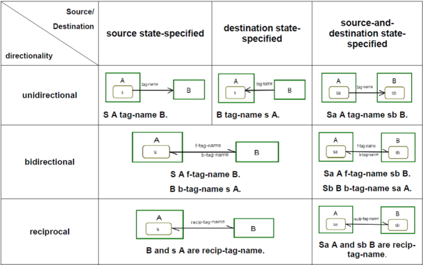
- State-specified tagged structural relations and links: is a structural relation between a state of an object or value of an attribute and another object or its state or value, meaning that these two entities are associated with the tag expressing the semantics of the association. In case of a null tag (i.e., the tag is not specified), the corresponding default null tag is used. Three groups of state-specified tagged structural relations exist: (1) source state-specified tagged structural relation, (2) destination state-specified tagged structural relation, (3) source-and-destination state-specified tagged structural relation. Each of these groups includes the appropriate unidirectional, bidirectional, and reciprocal tagged structural relation, giving rise to seven kinds of state-specified tagged structural relation link and corresponding OPL sentences.
More information and examples can be found in [MBSE OPM Book, Dori, 2016] Chapter 3.3 “Adding structural links”
Relationship Cardinalities
- Object Multiplicity In Structural and Procedural Links:
Object multiplicity shall refer to a requirement or constraint specification on the quantity or count of object instances associated with a link. Unless a multiplicity specification is present, each end of a link shall specify only one thing instance. Multiplicity specifications may appear in the following cases:
- to specify multiple source or destination object instances for a tagged structural link of any kind;
- to specify a participant object with multiple instances in an aggregation-participation link, where a different participation specification may be attached to each one of the parts of the whole;
- to specify an object with multiple instances in a procedural relation.
The syntax of an OPL sentence that includes an object with multiplicity shall include the object multiplicity preceding the object name, with the object name appearing in its plural form.
Link Cardinalities Summary:
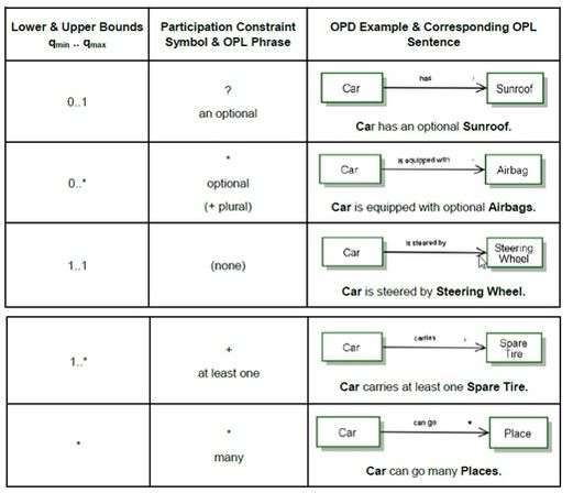
- Object Multiplicity Expressions and Constraints:
Object multiplicity may include arithmetic expressions, which shall use the operator symbols "+", "–", "*", "/", "(", and ")" with their usual semantics and shall use the usual textual correspondence in the corresponding OPL sentences.
An integer or an arithmetic expression may constrain object multiplicity. Graphically, expression constraints shall appear after a semicolon separating them from the expression that they constrain and shall use the equality/inequality symbols "=", "<", ">", "<=", and ">=", the curly braces "{" and "}" for enclosing set members, and the membership operator "in" (element of, ∈), all with their usual semantics. The corresponding OPL sentence shall place the constraint phrase in bold letters after the object to which the constraint applies in the form ", where constraint".
- Attribute Value and Multiplicity Constraints:
The expression of object multiplicity for structural and procedural links specifies integer values or parameter symbols that resolve to integer values. In contrast, the values associated with attributes of objects or processes may be integer or real values, or parameter symbols that resolve to integer or real values, as well as character strings and enumerated values. Graphically, a labelled, rounded-corner rectangle placed inside the attribute to which it belongs shall denote an attribute value with the value or value range (integers, real numbers, or string characters) corresponding to the label name. In OPL text, the attribute value shall appear in bold face without capitalization.
The syntax for an object with an attribute value OPL sentence shall be: Attribute of Object is value.
The syntax for an object with an attribute value range OPL sentence shall be: Attribute of Object range is value-range. A structural or a procedural link connecting with an attribute that has a real number value may specify a relationship constraint, which is distinct from an object multiplicity.
Graphically, an attribute value constraint is an annotation by a number, integer or real, or a symbol parameter, near the attribute end of the link and aligning with the link.

Logical Operators: AND, XOR, and OR
- Logical AND Procedural Links:
The logical operators AND, XOR, and OR among procedural relations enable specification of elaborate process precondition and postcondition. Separate, non-touching links shall have the semantics of logical AND. In the example opening the Safe requires all three keys.

- Logical XOR and OR Procedural Links:
A group of two or more procedural links of the same kind that originate from, or arrive at, the same object or process shall be a link fan. A link fan shall follow the semantics of either a XOR or an OR operator. The link fan end that is common to the links shall be the convergent link end. The link end that is not common to the links shall be the divergent link end.
The XOR operator shall mean that exactly one of the things in the span of the link fan exists, if the divergent link end has objects, or happens, if the divergent link end has processes. Graphically, a dashed arc across the links in the link fan with the arc focal point at the convergent end point of contact shall denote the XOR operator.
The OR operator shall mean that at least one of the two or more things in the span of the link fan exists, if the divergent link end has objects, or happens, if the divergent end has processes. Graphically, two concentric dashed arcs across the links with their focal point at the convergent end point of contact shall denote the OR operator.
- State-Specified XOR and OR Link Fans:
Each one of the link fans in shall have a corresponding state-specified version, where the source and destination may be specific object states or objects without a state specification. Combinations of state-specified and stateless links as destinations of a link fan may occur.

- Control-Modified Link Fans:
Each one of the XOR link fans for consumption, result, effect, and enabling links and their state-specified versions shall have
a corresponding control-modified link fan: an event link fan and a condition link fan. The example presents the event and condition effect link fans, as representatives of the basic (non-state-specified) links version of the modified link fans.

- Link Probabilities and Probabilistic Link Fans
A process P with a result link that yields a stateful object B with n states s1 through sn shall mean that the probability of generating B at each one of its states shall be 1/n. The single result link shall be used instead of the result link fan. Usually, probabilities of following a specific link in a link fan are not equal. Link probability shall be a value assigned to a link in a XOR diverging link fan that specifies the probability of following that particular link among the possible links in the fan link. A probabilistic link fan shall be a link fan with probability annotations on each fan link, where the sum of the probabilities shall be exactly 1. Graphically, along each fan link an annotation shall appear in the form Pr=p, where p is the link probability numeric value or a parameter, which denotes the probability of the system control to select and follow that particular link of the fan. The corresponding OPL sentence shall be the XOR diverging link fan sentence without link probabilities omitting the phrase "exactly one of…" and the phrase "…with probability p" following each things name with a probability annotation "Pr=p".

- Execution Path And Path Labels
A path label shall be a label along a procedural link, which, in the case that there is more than one option to follow upon process termination, prescribes that the link to follow will be the one having the same label as the one which we entered the process, A path label is a label on a procedural link that removes the ambiguity arising from multiple outgoing procedural links by specifying that the link to be followed is the one with the same label as the one with which the process was entered.
OPM Modeling Principles and Model Comprehension
System function and modeling purpose is to guide the scope and level of detail of an OPM model. The definition of system purpose, scope, and function in terms of boundary, stakeholders and preconditions is the basis for determining whether other elements should appear in the model. This determines the scope of the system model. OPM provides abstracting and refining mechanisms to manage the expression of model clarity and completeness. The model has a hierarchy tree for refinement, elaboration, or decomposition obtained by unfolding.[14][15]
Stakeholder and System's Beneficiary Identification
In order to start an OPM model of a system, the first step is to determine the function of the system - the main process of the system. A beneficiary of the artificial, man-made system is a stakeholder who receives functional value and benefits from the function of the system. For man-made systems this function is expected to benefit a person or a group of people—the beneficiary. After the function of the system aligns with the functional value expectation of its main beneficiary, the modeler identifies and adds other principal stakeholders to the OPM model. Modeling a system starts by defining, naming, and depicting the function of the system, which is also its top-level process.
System Diagram (SD) Level
The resulting top-level OPD is the System Diagram (SD), which includes the stakeholder group, in particular the beneficiary group, and additional top-level environmental things, which provide the context for the system's operation. The SD should contain only the central and important things – those things indispensable for understanding the function and context of the system. The function is the main process in SD, which also contains the objects involved in this process: the beneficiary, the operand (the object upon which the process operates), and possibly the attribute of the operand whose value the process changes. An OPM model fact needs to appear in at least one OPD in order for it to be represented in the model. SD should also contain an object representing the system that enables the function. The default name of this system is created by adding the word "System" to the name of the function. For example, if the function is Car Painting, the name of the system would be Car Painting System.

The OPD Tree
SD is always the only top-level OPD—it is the root of the OPD tree. The set of OPDs, organized as a process tree, which together specify the system. The OPD set keeps growing as additional OPDs are gradually constructed to increasingly refine the model and make it more concrete. The ability to add a descendant, subordinate OPD whenever the one currently under work reaches its congestion limits makes it possible to avoid over-cluttering any single OPD.
Clarity and Completeness Trade-Off
Clarity is the extent of unambiguous comprehension the system’s structure and behavior models convey. Completeness is the extent of specification for all the system's details. These two model attributes conflict with each other. On the one hand, completeness requires the full stipulation of system details. On the other hand, the need for clarity imposes an upper limit on the extent of detail within an individual model diagram, after which comprehension deteriorates because of clutter and overloading. Establishing an appropriate balance requires careful management of context during model development. However, the modeler may take advantage of the union of information provided by the entire OPD set of an OPM system model and have one OPD which is clear and unambiguous but not complete, and another that focuses on completeness for some smaller part of the system by adding more details.
OPM Refinement-Abstraction Mechanisms
OPM shall provide abstracting and refining mechanisms to manage the expression of model clarity and completeness. These mechanisms make possible the specification of contextualized model segments as separate, yet interconnected OPDs which, taken together, shall provide a model of the functional value providing system. These mechanisms shall enable presenting and viewing the system, and the things that comprise it, in various contexts that are interrelated by the objects, processes and relations that are common amongst them. Explicitly depicting the states of an object in an OPD may result in a diagram that is too crowded or busy, making it hard to read or comprehend. The OPM refinement-abstraction mechanisms shall be the following pairs of inverse operations: State expression and suppression, unfolding and folding, and in-zooming and outzooming.

State Expression and State Suppression
OPM shall provide an option for state suppression, i.e., suppressing the appearance of some or all the states within an object as represented in a particular OPD when those states are not necessary in that OPD's context. The inverse of state suppression shall be state expression, i.e., refining the OPD by adding the information concerning possible object states. The OPL corresponding to the OPD shall express only the states of the objects that are depicted.
Unfolding and Folding

Unfolding is a mechanism for refinement, elaboration, or decomposition. It reveals a set of things that are hierarchically below the unfolded thing. The result is a hierarchy tree, the root of which is the unfolded thing. Linked to the root are the things that constitute the context of the unfolded thing. Conversely, folding is a mechanism for abstraction or composition, which applies to an unfolded hierarchical tree.
In-Zooming and Out-Zooming
In-zooming is a kind of unfolding, which is applicable to aggregation-participation only and has additional semantics. For processes, in-zooming enables modeling the sub-processes, their temporal order, their interactions with objects, and passing of control to and from this context. For objects, in-zooming creates a distinct context that enables modeling the constituent objects spatial or logical order. Graphically, the timeline within the context of an in-zoomed process flows from the top of its process ellipse symbol to the ellipse bottom.
Meta Modeling

A metamodel is a model of a model. In particular, using OPM model to present aspects of OPM. The examples described here are a part of the comprehensive metamodels of OPM appear in an annex of ISO 19450.
OPM Model Structure
OPM model is a metamodel, as shown in the image of OPM model on the right. Using OPM to specify the structure of an OPM model of a system. It depicts the conceptual aspects of OPM as parallel hierarchies of the graphic and textual OPM modalities and their correspondence to produce equivalent model expressions.
An OPD Construct is the graphical expression of the corresponding textual OPL Sentence, which express the same model fact. An OPD and its corresponding OPL Paragraph are collections of model facts that a modeller places into the same model context.

Model of OPD Construct and Basic Construct
The model, as seen in the image of OPD metamodel, elaborates the OPD Construct concept. The purpose of this model is to distinguish Basic Construct from another possible OPD Construct. A Basic Construct is a specialization of OPD Construct, which consists of exactly two Things connected by exactly one Link, The non-basic constructs include, among others, those with link fans or more than two refinees.
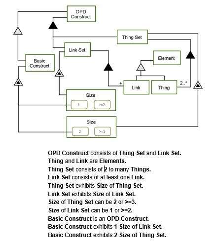
A modeller could add a process to the model, by adding states disconnected and connected of Thing Set. The purpose of the model thus includes the action of transforming a disconnected Thing Set to a connected Thing Set using the Link Set as an instrument of connection.
OPM Model of Thing
OPM model of Thing, is a model for an OPM Thing, showing its specialization into Object and Process, as depicted in the image of model of thing below. A set of States characterize Object, which can be empty, in a Stateless Object, or non-empty in the case of a Stateful Object. A Stateful Object with s States gives rise to a set of s stateless State-Specific Objects, one for each State. A particular State-Specific Object refers to an object in a specific state. Modelling the concept of State-Specific Object as both an Object and a State enables us to simplify the conceptual model by referring to an object and any one or its states by simply specifying Object.

OPM Model of Thing Generic Properties
OPM model of Thing generic properties, depicts Thing and its Perseverance, Essence, and Affiliation generic properties modelled as attribute refinees of an exhibition-characterization link. Perseverance is the discriminating attribute between Object and Process.
Essence is the discriminating attribute between Physical Object and Physical Process on the one hand, Informatical Object, and Informatical Process on the other hand. Affiliation is the discriminating attribute between Systemic Object and Systemic Process on the one hand, Environmental Object, and Environmental Process on the other hand.

In-Zooming and Out-Zooming Models
Both new-diagram in-zooming and new-diagram out-zooming create a new OPD context from an existing OPD context. New-diagram in-zooming starts with an OPD of relatively less details and adds elaboration or refinement as a descendant OPD that applies to a specific thing in the less detailed OPD.
New-diagram out-zooming starts with an OPD of relatively more details and removes elaboration or refinement to produce a less detailed, more abstract thing in an ancestor context.
New-diagram in-zooming elaborates a refineable present in an existing OPD, say SDn, by creating a new OPD, SDn+1, which elaborates the refineable by adding subprocesses associated objects, and relevant links. The new-diagram in-zooming and in new-diagram out-zooming processes are inverse operations.
New-Diagram In-Zooming and New-Diagram Out-Zooming models depicts the New-Diagram In-Zooming and New-Diagram Out-Zooming processes. The model on the right uses in-diagram in-zooming of the model on the left to elaborate the two processes, one for creating a new-diagram in-zoomed context and one for creating a new-diagram out-zoomed context.
New-Diagram In-Zooming begins with Content Showing, followed by Link Refining. New-Diagram Out-Zooming begins with Link Abstracting, the inverse process of Link Refining, followed by Content Hiding, the inverse process of Content Showing.
Standardization
ISO – the International Organization for Standardization – is an independent, non-governmental international organization with a membership of 162 national standards bodies, which develops voluntary, consensus-based, market relevant International Standards that support innovation and provide solutions to global challenges. These standards provide world-class specifications for products, services and systems, to ensure quality, safety and efficiency.
ISO and OPM
In June 2008, Richard Martin approached Prof. Dori after his presentation at the INCOSE International Symposium in Utrecht, the Netherlands, to inquire about the possibility of creating an International Standard for OPM. Mr. Martin, convener of ISO TC184/SC5/WG1 for automation systems interoperability architecture and modelling, had for some time been searching for methodologies offering more than static information and process modeling. He provided Prof. Dori with a simple example to model that could demonstrate both the modelling capability of OPM and its dynamic simulation opportunity.
In May 2010, Prof. Dori presented a brief overview of OPM and his demonstration model at the ISO Technical Committee 184/Sub-Committee 5 (TC184/SC5) plenary meeting, which then adopted a resolution to create and OPM Study Group for the purpose of examining the potential for OPM to enhance the standards created by SC5.
The OPM Study Group began its work in October 2010 and issued an interim report for the 2011 SC5 Plenary. The report included several uses of OPM to model existing SC5 standards and led to an initial motivation for the standardization of OPM with the realization that being text-based, ISO standards are prone to suffer from inconsistencies and incomplete information. This deficiency could be significantly reduced if the standards were model-based rather than text-based, and OPM offered a useful underlying modeling paradigm for this purpose.
A final OPM Study Group Report and a draft for a metamodel for model-based standards authoring document were delivered at the 2012 SC5 Plenary. As the OPM Study Group effort progressed, it became obvious that OPM could also serve as a solid and comprehensive basis for model-based systems engineering (MBSE) and for modeling both natural and man-made systems.
ISO 19450 Document
TC184/SC5/WG1 participants received the first draft of the OPM PAS in September 2011 with 16 pages, 2 annexes and a bibliography for a total of 25 pages. Most of the content simply identified sub-clause headings and space holder graphics. By the 2012 SC5 Plenary, the PAS draft included 10 full clauses describing OPM features and 6 annexes totaling 86 pages. One annex was an EBNF (Extended Backus-Naur Form, used to formally specify context free languages, enabling parsing of programming languages) specification for OPL and another detailed OPD graph grammar. To facilitate verification of the EBNF specification, Mr. David Shorter wrote a script to evaluate consistency and completeness of the EBNF statement set. Further effort to add meaningful examples and complete all of the identified sections resulted in a draft of 138 pages by the time of the 2013 SC5 Plenary. Subsequently, the working draft was registered with the SC5 Secretariat as a Committee Draft for initial circulation to SC5 members.
Because the SC5 resolution calling for the OPM specification indicated that the document was to be registered as a Publicly Available Specification (PAS), it would have only one acceptance ballot opportunity. In April 2014, the New Work Item Proposal and revised Committee Draft for ISO/PAS 19450 was delivered to SC5 for consideration. By now the Committee Draft was 98 pages plus front matter, four annexes and 30 bibliographic references, totaling 183 pages. In March 2015, ISO registered the result of balloting for ISO/PAS 19450 as 8 Approve, 1 Approve with comments, and 1 abstain.
ISO/PAS 19450 was formally published with a total of 162 pages by ISO on December 15, 2015, culminating a six-year effort to provide the standardization community with a formal specification for a new approach to modeling that binds together graphics and textual representations into a single paradigm suitable for automated simulation of model behavior.
OPM VS. SysML
OPM and SysML represent two different approaches to system modeling. SysML is defined as an extension of the Unified Modeling Language (UML) using UML's profile mechanism. In SysML up to nine diagrams are used, which are independently derived, and may not be completely consistent. In OPM, only one main diagram emerges. The need to integrate several kinds of diagrams may be more complicated. In OPM there is a combination between complex – the inherent fact that a system contains many parts interacting in multiple, often inexplicable ways, and complexity – the way a system model is presented through a certain modeling language and is perceived by a user. OPM with its minimal ontology of stateful objects and processes favorably responds to the challenge of reducing the complexity of the representation to the bare necessities without sacrificing accuracy and details.

OPM VS. UML
The differences between OPM and UML are highly perceivable during the analysis and design stages. While UML is a multiple-view, OPM supports a single unifying structure-behavior view. The crucial differences stem from the structure-oriented approach of UML, in which behavior is spread over thirteen diagram types, a fact that inevitably invokes the model multiplicity problem.[16] First, using OPM model enables to view at main diagram (SD) the main process, objects and the connection between them. In addition, it easy to understand what is the main system's benefit (presented at the SD). In OPM, it's also easier to understand the main three aspects of the system: behavior, structure and functionality (contrary to UML which describe this aspects with different types of diagrams). Database unfolding modeling contributes to the understanding of system and all details which is stored in the system. In addition, creating in zooming enable to simplify the model. OPM requires extensive knowledge of systematic processes such as how the system saved the path and gets decisions.
Generating SysML Views from an OPM Model
OPM (Object-Process Methodology) and SysML (OMG Systems Modeling Language) are two state-of-the-art conceptual modeling languages. While both languages aim at the same purpose of providing a means for general-purpose systems engineering, these languages take different approaches in realizing this goal.
In addition to the above, SysML is a profile of UML (Unified Modeling Language). Therefore, it is possible to convert an OPM diagram to an UML or SysML diagram.
An important note is that the OPM-to SysML translation is one-to-many in the sense that a single OPM element (entity or link) usually translates to several SysML elements that belong in different SysML diagram types.
For example, an OPM process, which is defined as an entity that transforms (generates, consumes, or changes the state of) an object, can be mapped to any subset of the following SysML entities:
• Use case (in a Use Case Diagram)
• Action (in an Activity Diagram)
• State transition trigger (in a State Machine Diagram).
As OPM and SysML are two distinct and differently designed languages, not all the constructs in one language have equivalent constructs in the other language.
One of the diagrams in UML that can be generated from an OPM diagram is the Use Case Diagram which is intended for modeling the usage of a system. The main elements comprising the Use Case Diagram are actors and use cases (the entities) along with the relationships (links) among them. Generation of a Use Case Diagram from OPM is therefore based on environmental objects (the actors) and the processes (the use cases) linked to them. Figure 1 is an example of Use Case Diagram generation of SD0. The figure shows the root OPM diagram (a), the corresponding OPL text (b), and the created Use Case Diagram (c). Figure 2 shows a SD1 level of OPD from the same OPM model (a), and the generated Use Case Diagram(b). The mapping scheme from OPM to the Use Case Diagram is summarized in Table I.
 Figure1 |
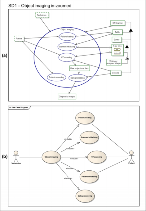 Figure 2 |
|---|
The second type of diagram is the Block Definition Diagram which is defines features of blocks (like properties and operations) and relationships between blocks, such as associations and generalizations. Generating a BDD is based upon the systemic objects of the OPM model and their relationships— mainly structural relations to other model elements.
The third type of diagram is the activity diagrams which are intended to specify flow. Key components included in the Activity Diagram are actions and routing flow elements. In our context, a separate Activity Diagram can be generated for each OPM process containing child subprocesses, i.e., a process which is in-zoomed in the OPM model. There are two kinds of user parameters that can be specified via the settings dialog. The first one deals with selection of the OPM processes: One option is to explicitly specify the required OPM processes by selection from a list. The alternative, which is the default option, is to start with the root OPD (SD) and go down the hierarchy. Here we reach the second parameter (that is independent of the first one), which is the required number of OPD levels (k) to go down the hierarchy. In order to give the user control over the level of abstraction, the diagrams are generated up to k levels down the hierarchy. Each level will result in the generation of an additional Activity Diagram, which is a child activity (subdiagram) contained in the enclosing higher-level activity. The default setting for this option is “all levels down” (i.e., “k = ∞”). The mapping scheme from OPM to Activity Diagram is summarized in Table III.

In order to assess and examine the effectiveness of the newly developed OPM-to-SysML algorithm and application, Prof. Dov Dori and B.Sc. Yariv Grobshtein performed a controlled experiment, which had two major goals:
(1) Since improved system comprehension was among the potential predicted benefits, they ventured to examine whether the additional SysML diagrams that had been generated automatically with their new application, affected system model comprehension;
(2) they wished to test the quality of the autocreated diagrams, mainly in terms of modeling errors and inconsistencies with the original OPM model from which they were generated. they carried out the experiment within a lecture of the course “Enterprise Systems Modeling” taught during the 2008 Spring semester at the Technion—Israel Institute of Technology. A total of 78 students participated in the experiment. The background of the students in systems modeling was based mainly on a mandatory prerequisite course “Specification and Analysis of Information Systems,” which they had taken in a previous semester. This course covered, among other topics, system development lifecycle and two modeling techniques: OPM and UML.
The experiment was conducted in the middle of the semester and was executed in an examination like setting: The students got printed forms with questions, and were asked to write their answers and return the forms. Model specifications of two systems provided the basis for the experiment. They handed two printed versions of each of these two systems. One version contained only the original OPM diagrams, while the other version contained the same OPM diagrams along with some automatically-generated SysML diagrams. They analyzed each of the two systems separately by taking the sum of all the eight comprehension questions. To determine whether there is a significant difference in the overall comprehension level between the OPM-only model specification and the OPM-and-SysML one. Testing the null hypothesis that there is no difference in comprehension level between the OPM-only model and the combined OPM-and-SysML model, against the two-sided alternative that there is a difference, they reject the null hypothesis in both cases. For both systems, the students’ answers to comprehension questions relating the combined OPM-and-SysML models were significantly better than answers relating to OPM-only models.
It seems that the additional diagrams were helpful in answering some of the questions more than the others. Only one question of eight in each of the cases scored lower when the combined diagrams specification was used. The SysML diagram that seems to have the biggest added value is the Block Definition Diagram (BDD), which specifies system hierarchy and features of blocks like attributes and operations. The relatively high helpfulness of the BDD is evident from both the students’assessment of the contribution of this diagram type and from analysis of the scores in the individual questions in both systems. According to the results of the experiment, the Use Case diagram seems to have the least effect on system comprehension, and this is also in agreement with the students’ assessment of the Use Case diagram type contribution. In between are the Activity diagram and the State Machine diagram, which appear to have a positive effect, albeit not as high as the effect of the BDD.
As noted, the other goal of the experiment was to assess the quality of the OPM-to-SysML application in terms of errors and inconsistencies between the source OPM model and the generated SysML diagrams. In this regard, the students did not find any issues of errors, inconsistencies, or contradictions associated with the SysML diagrams, indicating that the application has achieved a high level of model-tomodel translation fidelity. The ignificant improvement in the level of comprehension is also a positive indicator for the quality of the application in this sense.
Overall, we can summarize the results of the experiment with two main conclusions. The first conclusion is that enriching OPM with additional views, specifically certain SysML diagram types, improves the understanding of a given system model. While previous studies suggested that OPM is better than UML in terms of comprehension,[17][18] in our case the SysML views were used in addition to the OPM diagrams, not instead of them. This way, stakeholders involved in system development can have the best of both worlds. It may be interesting to conduct an experiment with a larger scope to examine the level of comprehension with a third alternative of SysML-only diagrams. The second conclusion concerns the quality of the algorithm and application we developed for automatic generation of SysML views from an OPM model. Since the SysML diagrams in the experiment were generated automatically using this application, the outcomes suggest that the application we developed is indeed effective and achieves its purpose of faithfully translating OPM to SysML. Demonstrating that it is possible to automatically create useful SysML views makes the approach of enriching OPM with additional diagrams worth pursuing. Overall, the experiment result of improved systems understanding confirms a major potential benefit of the additional SysML views that complement the OPM model. The significant experiment results suggest having a subset of SysML views created and visualized in real time by the modeling tool. Keeping the SysML views in sync with the OPM model while creating and modifying the OPM diagrams seems to have significant added value for the modeler in the modeling process. A similar approach is taken by OPCAT with the textual representation of OPM (OPL), and from our experience it seems to be very helpful.
In the study was developed and applied an algorithm for automatic SysML views generation from an OPM model. For each SysML view, a mapping scheme from OPM elements to SysML elements constitutes the foundation for the OPM-toSysML sub algorithm and translation engine application. The mappings are partial and do not utilize all the available language elements. The software implementation was demonstrated into OPCAT, the OPM-supporting modeling tool.
See also
- Unified Modeling Language
- International Organization for Standardization
- Systems Modeling Language (SysML)
References
- 1 2 Dori, Dov (1995). "Object-Process Analysis: Maintaining the Balance between System Structure and Behavior". Journal of Logic and Computation. 5 (2): 227–249. doi:10.1093/logcom/5.2.227.
- 1 2 Dori, Dov (2002). Object-Process Methodology – A Holistic Systems Paradigm. Berlin, Heidelberg, new York: Springer Verlag. p. 453. ISBN 3-540-65471-2. Retrieved 29 December 2015.
- 1 2 Dori, Dov (2016). Model-Based Systems Engineering with OPM and SysML. New York, NY: Springer. p. 430.
- ↑ Booch, G. Time for a ceasefire in the methods war, Journal of Object-Oriented Programming, July/August 1993
- ↑ Dori, D.A Holistic Systems Paradigm, Springer Verlag, Berlin,Heidelberg, New York, 2002 (ISBN 3-540-65471-2; Foreword by Edward Crawley. Hard cover, 453 pages, with CD-ROM).
- ↑ Dori, D. Model-Based Systems Engineering with OPM and SysML, Springer, New York, 2016 (Foreword by Edward Crawley. Hard cover, 453 pages, in press).
- ↑ "Automation systems and integration — Object-Process Methodology". ISO.
- ↑ "Enterprise Systems Modeling Laboratory". Enterprise Systems Modeling Laboratory.
- ↑ Dori, D. Model-Based Systems Engineering with OPM and SysML, July 12, 2015 (page 2)
- ↑ Dori, Dov; Linchevski, Chen; Manor, Raanan (2010). "OPCAT – A Software Environment for Object-Process Methodology Based Conceptual Modelling of Complex Systems". Proc. 1st International Conference on Modelling and Management of Engineering Processes. University of Cambridge, Cambridge, UK, Heisig, P., Clarkson, J., and Vajna, S. (Eds.): 147–151.
- ↑ http://esml.iem.technion.ac.il/
- 1 2 Dori, D. Model-Based Systems Engineering with OPM and SysML,July 12, 2015 (page 3)
- ↑ The mRNA Lifecycle
- ↑ "Automation systems and integration — Object-Process Methodology". ISO.
- ↑ Dori, Dov (2016). Model-Based Systems Engineering with OPM and SysML. New York, NY: Springer. p. 430.
- ↑ Peleg, M.; Dori, D. (2000). "The Model Multiplicity Problem: Experimenting with Real-Time Specification Methods". IEEE Tran. on Software Engineering. 26 (8): 742–759. doi:10.1109/32.879812.
- ↑ Reinhartz-Berger and Dori (2005). "Generating SysML Views from an OPM Model".
- ↑ Peleg and Dori (2000). "Generating SysML Views from an OPM Model".
Further reading
- Dori, D. (1995). "Object-Process Analysis: Maintaining the Balance between System Structure and Behavior". Journal of Logic and Computation. 5 (2): 227–249. doi:10.1093/logcom/5.2.227.
- D. Dori (2002). Object-Process Methodology – A Holistic Systems Paradigm. Springer Verlag, New York.
- Daniel Amyot, Gunter Mussbacher (2001). "Bridging the requirements/Design Gap in Dynamic Systems with Use Case Maps (UCMs)"
- I. Reinhartz-Berger and D. Dori (2004). "Object-Process Methodology (OPM) vs. UML: A Code Generation Perspective"
External links
| Wikimedia Commons has media related to Object Process Methodology. |
- Object-Process Methodology and Its Application to the Visual Semantic Web, presentation by Dov Dori, 2003.
- Formalizing the Conceptual Modeling Thought Process to Benefit Engineers and Scientists., presentation by Dov Dori, 2015.
- Formalizing the Conceptual Modeling Thought Process to Benefit Engineers and Scientists
- System engineering and architecture: principles, models, tools and application.