Multiway switching
In building wiring, multiway switching is the interconnection of two or more electrical switches to control an electrical load (often, but not always, lighting) from more than one location. For example, this allows lighting in a hallway, stairwell, or large room to be controlled from multiple locations. While a "normal" light switch needs to be only a single pole, single throw (SPST) switch, multiway switching requires the use of switches that have one or more additional contacts and two or more wires must be run between the switches. When the load is controlled from only two points, single pole, double throw (SPDT) switches are used. Double pole, double throw (DPDT) switches allow control from three or more locations.
In alternative designs, low-voltage relay or electronic controls can be used to switch electrical loads, sometimes without the extra power wires.
Three-way and four-way switches

The controlled load is often a lamp, but multiway switching is used to control other electrical loads, such as an electrical outlet, fans, pumps, heaters, or other appliances. The electrical load may be permanently hard-wired, or plugged into a switched receptacle.
Three-way and four-way switches make it possible to control a light from multiple locations, such as the top and bottom of a stairway, either end of a long hallway, or multiple doorways into a large room. These switches appear externally similar to single pole, single throw (SPST) switches, but have extra connections which allow a circuit to be controlled from multiple locations. Toggling the switch disconnects one "traveler" terminal and connects the other.
Electrically, a typical "3-way" switch is a single pole, double throw (SPDT) switch. By correctly connecting two of these switches together, toggling either switch changes the state of the load from off to on, or on to off. The switches may be arranged so that they are in the same orientation for off, and contrasting orientations for on.[1]
A "4-way" (intermediate) switch is a purpose built double pole, double throw (DPDT) switch, internally wired in manufacture to reverse the connections between the input and output and having only four external terminals. This switch has two pairs of "traveler" terminals that it connects either straight through, or crossed over (transposed, or swapped). An intermediate switch can, however, be implemented by adding appropriate external wiring to an ordinary (six terminal) DPDT switch, or by using a separate DPDT relay.
By connecting one or more 4-way (intermediate) switches in-line, with 3-way switches at either end, the load can be controlled from three or more locations. Toggling any switch changes the state of the load from off to on, or from on to off.
Number and common types of wires
In this article, when comparing different wiring methods or systems the focus is on the number of wires connecting the switches to each other. Sometimes an additional wire is present in each cable to carry an unswitched neutral or hot wire which passes through the switch mounting box, but is not normally connected to the switch. If the switch has a pilot light or a receptacle, additional hot or neutral connections to the device may be required. Grounding (earthing) wires are not counted.
More specifically (in the United States), the most common wiring used in residential applications includes either 14 gauge (15 Amp circuits) or 12 gauge (20 Amp circuits). The 'basic' cable (also often called 'Romex' which is a brand name of Southwire) consists of two insulated (plastic coated) solid copper wires: black (for hot/load), white (neutral), and a 'bare' wire for ground. A paper sheathing wraps the copper ground and all 3 are plastic sheathed typically in either white or yellow plastic sheathing (used for interior use).
Depending on the local electrical codes, interior cable may be used acceptably in exterior conditions provided it is run through conduit protective pipe. UF style cable (grey sheathed) for exterior use typically need not be run through conduit. UF cable sheathing can resist UV and other environmental issues that interior wire sheathing cannot. Codes specify the required buried depths depending on whether the ground covering the cable is bare soil or the cable will run under concrete protected surfaces (concrete pathway or driveway, etc.)
While there are '3 wires' in the basic sheathed cable, in the USA it's referred to by its gauge and the number of the insulated (non-ground wires). Thus, 14-2 ("fourteen two") describes 14 gauge wires (black, white, ground). 12-2 describes the next thickest wire, 12 gauge. These types of cable are used for most (single pole) switches and receptacles.
14-3, 12-3 etc. refer to sheathed cable with an additional insulated wire, typically red in color. This wire is required when multiway switches will be used such as two 3 way switches used to control one or more lights from 2 separate locations. Depending on the configuration, typically black represents hot/feed from the service panel and the other black to the load (light), with the white and red serving as the travelers. In some variations, the white wire recoded (retaped) black will be required as a traveler. There are many 3 way switch configurations such as powering the circuit through one or the other switch or the light fixture.
Two locations
Switching a load on or off from two locations (for instance, turning a light on or off from either end of a flight of stairs) requires two SPDT switches. There are several arrangements of wiring to achieve this.
Traveler system
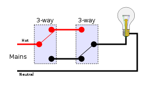
In the traveler system, also called the "common" system, the power line (hot, shown in red) is fed into the common terminal of one of the switches; the switches are then connected to each other by a pair of wires called "travelers" (or "strappers" in the UK), and the lamp is connected to the common line of the second switch, as shown.
Using the traveler system, there are four possible combinations of switch positions: two with the light on and two with the light off.
Off On 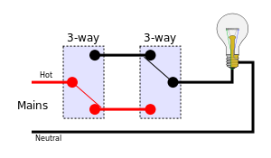


Alternative system

In an alternative situation of two switches and a single switched load this system offers no advantage, and in fact has the disadvantage of requiring four wires (including neutral) between "ends" of the installation, compared to three wires in the traveler system.
However, in the unusual case in which a switched load is wanted at both ends (e.g. illuminating a long hallway), and an unswitched load (e.g. receptacle) is wanted at both ends as well, this system's four wires saves one wire compared to the standard system, which would require five wires (two travelers, one neutral, one unswitched-hot, one switched-hot) to serve all these loads. However, in this application the system cannot be extended (e.g. with "four way" switches) to offer more than two switch locations.
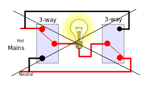
Carter system
The Carter system was a method of wiring 3-way switches in the era of early knob-and-tube wiring. This now-obsolete wiring method has been prohibited by the USA National Electrical Code since 1923,[2] even in new knob-and-tube installations which are still permitted under certain circumstances. This wiring system may still be encountered in older "grandfathered" electrical installations.
In the Carter system, the incoming live (energized) and neutral wires were connected to the traveler screws of both 3-way switches, and the lamp was connected between the common screws of the two switches. If both switches were flipped to hot or both were flipped to neutral, the light would remain off; but if they were switched to opposite positions, the light would illuminate. The advantage of this method was that it used just one wire to the light from each switch, having a hot and neutral in both switches.
The major problem with this method is that in one of the four switch combinations the socket around the bulb is electrified at both of its terminals even though the bulb itself is not lit. As the shell may be energized, even with the light switched off, this poses a risk of electrical shock when changing the bulb. This method is therefore prohibited in modern building wiring.
More than two locations
For more than two locations, two of the interconnecting wires must be passed through an intermediate switch, wired to swap or transpose the pair. Any number of intermediate switches can be inserted, allowing for any number of locations. This requires two wires along the sequence of switches.
Traveler system
Using three switches, there are eight possible combinations of switch positions: four with the light on and four with the light off. Note that these diagrams also use the American electrical wiring names.
Off On 
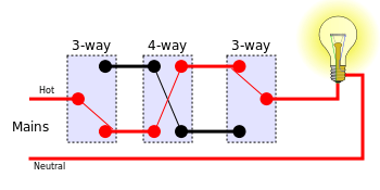


As mentioned above, the above circuit can be extended by using multiple 4-way switches between the 3-way switches to extend switching ability to any number of locations.
Wiring guidelines

Switches built to North American standards identify the terminals by color-coding. The common is often colored black, and the pair of traveler connections often colored gold. There is no standard for indicating the terminals on 4-way switches, so they may need to be checked with a meter or a continuity tester to deduce the internal contacts.
Most electricians know these simple guidelines when wiring multiway switching.
See the diagram above titled, Four sample arrangements, for illustration.
Note: The green-colored terminal on modern switches is for the "safety ground". Although the "safety ground" conductor is not shown in the illustration above, an additional conductor for the "safety ground" should be used from the main panel (or subpanel), and between the "switchboxes", and to the "load". When, in the discussion below, the "safety ground" conductors are not explicitly specified, it will still be assumed that you use an extra conductor for it everywhere along the system.
- A minimum of two "3-way" (SPDT - single pole, double throw) switches are needed in a multiway switch setup. Each 3-way switch has a single dark-colored "common" terminal, and two gold-colored "traveler" terminals.
- If more than two switches are used, all additional switches need to be "4-way" (DPDT - double pole, double throw). Each 4-way switch has four gold-colored traveler terminals.
- On a 4-way switch, the traveler terminals are typically paired up on each side of the switch. In other words, one side of the switch will be used for the two 'incoming' wires, and the other side of the switch is for the two 'outgoing' wires. It is important that you establish if this is in fact the case with the particular switches you will use. Once you have confirmed, for example, that terminals are paired on each side, it does not matter which side you use for 'incoming' versus 'outgoing'. It also does not matter which of the two terminals on one side of the switch receives which of the two incoming traveler wires, or which of the two 'outgoing' wires.
- The switches are connected in a continuous linear series, with the two 3-way switches connected one-at-each-end of the series, and with any optional 4-way switches connected in between the 3-way switches. These switches deal strictly with the 'hot' conductors of the circuit. The neutral is not involved with the switches.
- The hot from the 'mains' will travel "unswitched" to the 'common' terminal of one of the two 3-way switches, and, typically, whatever switch is furthest from the 'load' is designated for this.
- The neutral from the 'mains' will travel "unswitched" to the 'load'.
- Typically, the switch closest to the load will be designated as the other 3-way switch. This 3-way switch's 'common' terminal is for the conductor that travels to, and connects to, the hot terminal of the load. For example, this wire would travel to the box for a light, and be connected to the light's hot wire, and not the light's neutral wire.
- Safety Note: It is important that the wire that travels from the 3-way switch's common terminal, to the box for the load, be connected to the hot side of the load, and NOT to the neutral side of the load.
The danger of not following that rule is perhaps best illustrated by considering, as an example, a light with a screw-in bulb. If you were to make the error of connecting the 'hot' from the 3-way switch's common terminal to the neutral wire of the light (or the light's neutral terminal), you will in fact have connected the 'hot' to the fixture's 'shell' (the threaded metal outer shell that the bulb screws into). Then, whenever the power is 'on' at the fixture, the shell is energized. If you then ever go to change the bulb without first being sure the power is off at the fixture, you will be at a greater risk of being shocked versus if you had not wired the 3-way hot to the load neutral. That is because now you will get 'shocked' if you touch the shell while changing the bulb if the fixture is powered, whereas if you had connected the hot from the 3-way switch to the light fixture's hot side, and if the power were on at the fixture when you change the bulb, the only way you could get shocked is by touching the small bare terminal that is all the way inside at the base of the shell.
If you have two wires coming out from the load that are the same color, or in other words, if you do not know which wire or terminal is hot versus neutral, you should determine which is which. For example, if you have two black wires, you can use a continuity tester to determine which one of the two wires is electrically continuous with one of the 'shells' for the bulbs, and is, therefore, the neutral wire.
- A 2-conductor cable (not including an extra third conductor for the 'safety ground') is all that is needed from the "mains" to one of the boxes. One conductor is for the "Hot" from the 'mains' (the service panel, or subpanel), and the other wire is for the "Neutral" from the mains.
- The 2-conductors from the mains can enter your multiway setup at any of the switch boxes, or even at the box for the load. The box closest to the mains is typically the one that receives the two conductors from the 'mains'.
- A 2-conductor cable (not including an extra third conductor for the 'safety ground') is all that is needed between the box at the load, and the 3-way switch closest to the load.
- Regardless of which box first receives the hot and neutral from the mains, the "hot" must travel unswitched, from there, to the 'common' terminal of the 3-way switch that is opposite-the-load in the multiway switch-series.
- Similarly, regardless of which box first receives the "neutral" from the 'mains', the "neutral" must continue 'unswitched' to the load's box and the load's "neutral" connection.
- A 3-conductor cable (not including an extra fourth conductor for the 'safety ground') is needed to connect all the switch boxes in a single line, starting from one 3-way switch, then to each multiway switch, and then terminating at the other 3-way switch.
- One pair of the three conductors is used to connect the 'traveler' terminals of one switch to the next switch in the series. These will be the 'hot' wires, and whenever the circuit is energized, one of these two wires, of the pair, will be 'energized'. If two of the three conductors are the same color, then use those for this 'hot' duty. For example, if you have two black conductors, and a white one, then use the black conductors as the 'hot' traveler wires for the traveler terminals. In any case, if one of the wires is white, save it for the next paragraph, and do not use it as one of the 'hot' travelers.
- The remaining "third-conductor" will pass through all of the boxes unswitched. And, depending upon which box receives the two conductors from the 'mains', this third conductor might be hot, or it might be neutral.
- The third-conductor will be used as an unswitched 'hot' conductor between the box receiving the mains hot, and the box for the 3-way switch furthest from the load.
- The third-conductor will be used as an unswitched neutral conductor between the box receiving the mains neutral, the box at the load.
- Please Note: In the USA, any time a white conductor is used for 'current-carrying' (that is, when it is not being used strictly for the "neutral" between the load and the 'mains'), it must be permanently re-identified at its terminations (and wherever visible) with a color other than white, gray, or green. [NFPA 70A 200.7 (C)(2) {and (1) for coloring}]
That NFPA regulation will be applicable, in the example above, when the third conductor is white, and if the hot and neutral from the mains enters the system at a box other than the box at the 3-way switch furthest from the load. In other words, the white conductor will be a 'current carrying' conductor between the mains 'entry point' and the 3-way switch opposite the load, and must be permanently identified as non-white.
Low voltage relay switching
Systems based on relays with low-voltage control circuits permit switching the power to lighting loads from an arbitrary number of locations. For each load, a latching relay is used that mechanically maintains its on- or off-state, even if power to the building is interrupted. Mains power is wired through the relay to the load.
Instead of running mains voltage to the switches, a low voltage—typically 24 V AC—is connected to remote momentary toggle or rocker switches. The momentary switches usually have SPDT contacts in an (ON)-OFF-(ON) configuration. Pushing the switch actuator in one direction causes the relay contacts to close; pushing it in the opposite direction causes the relay contacts to open. Any number of additional rocker switches can be wired in parallel, as needed in multiple locations. An optional master control can be added that turns all lights in the facility on or off simultaneously under the control of a timer or computer.
After an initial burst of popularity in the 1960s, residential use of such relay-based low voltage systems has become rare. Equipment for new installations is not commonly carried by electrical suppliers, although it is still possible to find parts for maintaining existing installations.
Electronic remote switching
As of 2012, multiway switching in residential and commercial applications is increasingly being implemented with power line signalling and wireless signalling techniques. These include the X10 system, available since the 1970s, and newer hybrid wired/wireless systems, such as Insteon and Z-Wave. This is particularly useful when retrofitting multi-way circuits into existing wiring, often avoiding the need to put holes in walls to run new wires.
Remote-control systems are increasingly used in commercial buildings as part of lighting systems under semi-automatic control, for better safety, security, and energy conservation.
References
- ↑ "Can I wire 3-way switches so that when they are both in the same orientation the light will be off?". Home Improvement Stack Exchange. 2014-12-22. Retrieved 2015-08-14.
- ↑ NEC Article 404.2 Switch Connections: (A) ... Three-way and four-way switches shall be wired so that all switching is done only in the ungrounded circuit conductor ... (B) Grounded Conductors. Switches or circuit breakers shall not disconnect the grounded conductor of a circuit. Switching a neutral is generally forbidden by the NEC unless the hot conductor is opened simultaneously
Further reading
| Wikimedia Commons has media related to Multiway switching diagrams. |