Microstrip antenna

In telecommunication, a microstrip antenna (also known as a printed antenna) usually means an antenna fabricated using microstrip techniques on a printed circuit board (PCB).[1] They are mostly used at microwave frequencies. An individual microstrip antenna consists of a patch of metal foil of various shapes (a patch antenna) on the surface of a PCB, with a metal foil ground plane on the other side of the board. Most microstrip antennas consist of multiple patches in a two-dimensional array. The antenna is usually connected to the transmitter or receiver through foil microstrip transmission lines. The radio frequency current is applied (or in receiving antennas the received signal is produced) between the antenna and ground plane. Microstrip antennas have become very popular in recent decades due to their thin planar profile which can be incorporated into the surfaces of consumer products, aircraft and missiles; their ease of fabrication using printed circuit techniques; the ease of integrating the antenna on the same board with the rest of the circuit, and the possibility of adding active devices such as microwave integrated circuits to the antenna itself to make active antennas.
Patch antenna
The most common type of microstrip antenna is the patch antenna. Antennas using patches as constitutive elements in an array are also possible. A patch antenna is a narrowband, wide-beam antenna fabricated by etching the antenna element pattern in metal trace bonded to an insulating dielectric substrate, such as a printed circuit board, with a continuous metal layer bonded to the opposite side of the substrate which forms a ground plane. Common microstrip antenna shapes are square, rectangular, circular and elliptical, but any continuous shape is possible. Some patch antennas do not use a dielectric substrate and instead are made of a metal patch mounted above a ground plane using dielectric spacers; the resulting structure is less rugged but has a wider bandwidth. Because such antennas have a very low profile, are mechanically rugged and can be shaped to conform to the curving skin of a vehicle, they are often mounted on the exterior of aircraft and spacecraft, or are incorporated into mobile radio communications devices.
Advantages
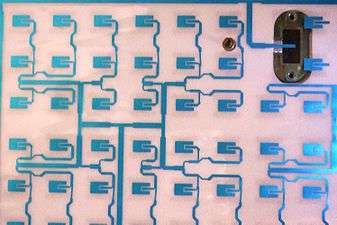
Microstrip antennas are relatively inexpensive to manufacture and design because of the simple 2-dimensional physical geometry. They are usually employed at UHF and higher frequencies because the size of the antenna is directly tied to the wavelength at the resonant frequency. A single patch antenna provides a maximum directive gain of around 6-9 dBi. It is relatively easy to print an array of patches on a single (large) substrate using lithographic techniques. Patch arrays can provide much higher gains than a single patch at little additional cost; matching and phase adjustment can be performed with printed microstrip feed structures, again in the same operations that form the radiating patches. The ability to create high gain arrays in a low-profile antenna is one reason that patch arrays are common on airplanes and in other military applications.
Such an array of patch antennas is an easy way to make a phased array of antennas with dynamic beamforming ability.[2]
An advantage inherent to patch antennas is the ability to have polarization diversity. Patch antennas can easily be designed to have vertical, horizontal, right hand circular (RHCP) or left hand circular (LHCP) polarizations, using multiple feed points, or a single feedpoint with asymmetric patch structures.[3] This unique property allows patch antennas to be used in many types of communications links that may have varied requirements.
Rectangular patch
The most commonly employed microstrip antenna is a rectangular patch which looks like a truncated microstrip transmission line. It is approximately of one-half wavelength long. When air is used as the dielectric substrate, the length of the rectangular microstrip antenna is approximately one-half of a free-space wavelength. As the antenna is loaded with a dielectric as its substrate, the length of the antenna decreases as the relative dielectric constant of the substrate increases. The resonant length of the antenna is slightly shorter because of the extended electric "fringing fields" which increase the electrical length of the antenna slightly. An early model of the microstrip antenna is a section of microstrip transmission line with equivalent loads on either end to represent the radiation loss.
Specifications
The dielectric loading of a microstrip antenna affects both its radiation pattern and impedance bandwidth. As the dielectric constant of the substrate increases, the antenna bandwidth decreases which increases the Q factor of the antenna and therefore decreases the impedance bandwidth. This relationship did not immediately follow when using the transmission line model of the antenna, but is apparent when using the cavity model which was introduced in the late 1970s by Lo et al.[4] The radiation from a rectangular microstrip antenna may be understood as a pair of equivalent slots. These slots act as an array and have the highest directivity when the antenna has an air dielectric and decreases as the antenna is loaded by material with increasing relative dielectric constant.
The half-wave rectangular microstrip antenna has a virtual shorting plane along its center. This may be replaced with a physical shorting plane to create a quarter-wavelength microstrip antenna. This is sometimes called a half-patch. The antenna only has a single radiation edge (equivalent slot) which lowers the directivity/gain of the antenna. The impedance bandwidth is slightly lower than a half-wavelength full patch as the coupling between radiating edges has been eliminated.
Other types
Another type of patch antenna is the planar inverted-F antenna (PIFA). The PIFA is common in cellular phones (mobile phones) with built-in antennas.[5][6] The antenna is resonant at a quarter-wavelength (thus reducing the required space needed on the phone), and also typically has good SAR properties. This antenna resembles an inverted F, which explains the PIFA name. The PIFA is popular because it has a low profile and an omnidirectional pattern.[7] These antennas are derived from a quarter-wave half-patch antenna. The shorting plane of the half-patch is reduced in length which decreases the resonance frequency.[8] Often PIFA antennas have multiple branches to resonate at the various cellular bands. On some phones, grounded parasitic elements are used to enhance the radiation bandwidth characteristics.
The folded inverted conformal antenna (FICA)[9] has some advantages with respect to the PIFA, because it allows a better volume reuse.
References
- ↑ Lee, Kai Fong,; Luk, Kwai Man (2011). Microstrip Patch Antennas. World Scientific. pp. 8–12. ISBN 184816453X.
- ↑ "Welcome to antennas 101" by Louis E. Frenzel, "Electronic Design" 2008
- ↑ Bancroft, R. Microstrip and Printed Antenna Design Noble Publishing 2004, chapter 2-3
- ↑ Lo, Y.T., Solomon D. and Richards, W.F. "Theory and Experiment on Microstrip Antennas," IEEE Transactions on Antennas and Propagation, AP-27, 1979 pp. 137-149.
- ↑ "PIFA - The Planar Inverted-F Antenna".
- ↑ Iulian Rosu. "PIFA – Planar Inverted F Antenna".
- ↑ Taga, T. Tsunekawa, K. and Saski, A., "Antennas for Detachable Mobile Radio Units," Review of the ECL, NTT, Japan, Vol. 35, No.1, January 1987, pp. 59-65.
- ↑ "Inverted-F Antenna (IFA)" at antenna-theory.com
- ↑ Di Nallo, C.; Faraone, A., "Multiband internal antenna for mobile phones," Electronics Letters , vol.41, no.9, pp. 514-515, 28 April 2005
External links
- Microstrip Antennas antenna-theory.com
- Microstrip Antenna Tutorial EM Talk
- Microstrip Patch Antenna Calculator
- The basics of patch antenna
- Design of a Patch Antenna