Leakage inductance
Leakage inductance derives from the electrical property of an imperfectly-coupled transformer whereby each winding behaves as a self-inductance constant in series with the winding's respective ohmic resistance constant, these four winding constants also interacting with the transformer's mutual inductance constant. The winding self-inductance constant and associated leakage inductance is due to leakage flux not linking with all turns of each imperfectly-coupled winding.
The leakage flux alternately stores and discharges magnetic energy with each electrical cycle acting as an inductor in series with each of the primary and secondary circuits.
Leakage inductance depends on the geometry of the core and the windings. Voltage drop across the leakage reactance results in often undesirable supply regulation with varying transformer load. But it can also be useful for harmonic isolation (attenuating higher frequencies) of some loads.[1]
Although discussed exclusively in relation to transformers in this article, leakage inductance applies to any imperfectly-coupled magnetic circuit device including especially motors.[2]
Leakage inductance and coupling coefficient
The magnetic circuit's flux that does not interlink both windings is the leakage flux corresponding to primary leakage inductance LPσ and secondary leakage inductance LSσ. These leakage inductances are defined in terms of transformer winding open-circuit inductances as well as the transformer's coupling coefficient k, the primary open-circuit self-inductance being given by

where


and
- = Primary inductance
- = Primary self-inductance
- = Primary leakage inductance
- = Magnetizing inductance referred to the primary


It therefore follows that the transformer secondary open-circuit self, magnetizing and leakage inductances are given by

where


and
- = Secondary inductance
- = Secondary self-inductance
- = Secondary leakage inductance
- = Magnetizing inductance referred to the secondary
- = Winding turns ratio.


The electric validity of the above transformer diagram depends strictly on open circuit conditions for the respective winding inductances considered, more generalized circuit conditions being as developed in the next two sections.
Leakage factor and inductance
A real linear two-winding transformer can be represented by two mutual inductance coupled circuit loops linking the transformer's five impedance constants as shown in the diagram at right, where,[3][4]
- M is mutual inductance
- LP & LS are primary and secondary winding self-inductances
- RP & RS are primary and secondary winding resistances
- Constants M, LP, LS, RP & RS are measurable at the transformer's terminals
- Coupling coefficient k is given as
- , with 0 < k < 1
- Winding turns ratio a is in practice given as
- .[5]


The two circuit loops can be expressed by the following voltage and flux linkage equations,[6]
- ,
- where
- ψ is flux linkage
- dψ/dt is derivative of flux linkage with respect to time.


These equations can be developed to show that, neglecting associated winding resistances, the ratio of a winding circuit's inductances and currents with the other winding short circuited and at no-load is as follows,[7]
- ,

where,
- σ is the leakage factor or Heyland factor
- ioc & isc are no-load and short circuit currents
- Loc & Lsc are no-load and short circuit inductances.
The transformer can thus be further defined in terms of the three inductance constants as follows,[8][9]
- ,


where,
- LM is magnetizing inductance, corresponding to magnetizing reactance XM
- LPσ & LSσ are primary & secondary leakage inductances, corresponding to primary & secondary leakage reactances XPσ & XSσ.
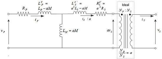
The transformer can be expressed more conveniently as the first shown equivalent circuit with secondary constants referred (i.e., with prime superscript notation) to the primary,[8][9]
- .


Since
and
- ,

we have
- ,

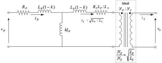
which allows expression as second shown equivalent circuit with winding leakage and magnetizing inductance constants as follows,[10]
- .


Expanded leakage factor
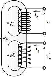
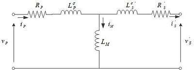
The real transformer can be simplified as shown in third shown equivalent circuit, with secondary constants referred to the primary and without ideal transformer isolation, where,
- iM = iP - iS'
- iM is magnetizing current excited by flux ΦM that links both primary and secondary windings.
Referring to the flux diagram at right, the winding-specific leakage factor equations can be defined as follows,[11]
- σP = ΦPσ/ΦM = LPσ/LM
- σS = ΦSσ'/ΦM = LSσ'/LM
- ΦP = ΦM + ΦPσ = (1 + σP)ΦM
- ΦS' = ΦM + ΦSσ' = (1 + σS)ΦM
- LP = LM + LPσ = (1 + σP)LM
- LS' = LM + LSσ' = (1 + σS)LM,
where
- σP is primary leakage factor
- σS is secondary leakage factor
- Φ is magnetic flux.
The leakage factor σ can thus be expanded in terms of the interrelationship of above winding-specific inductance and leakage factor equations as follows:[12]
- .

Leakage inductance in practice
Leakage inductance can be an undesirable property, as it causes the voltage to change with loading. In many cases it is useful. Leakage inductance has the useful effect of limiting the current flows in a transformer (and load) without itself dissipating power (excepting the usual non-ideal transformer losses). Transformers are generally designed to have a specific value of leakage inductance such that the leakage reactance created by this inductance is a specific value at the desired frequency of operation.
Commercial transformers are usually designed with a short-circuit leakage reactance impedance of between 3% and 10%. If the load is resistive and the leakage reactance is small (<10%) the output voltage will not drop by more than 0.5% at full load, ignoring other resistances and losses.
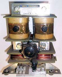
High leakage reactance transformers are used for some negative resistance applications, such as neon signs, where a voltage amplification (transformer action) is required as well as current limiting. In this case the leakage reactance is usually 100% of full load impedance, so even if the transformer is shorted out it will not be damaged. Without the leakage inductance, the negative resistance characteristic of these gas discharge lamps would cause them to conduct excessive current and be destroyed.
Transformers with variable leakage inductance are used to control the current in arc welding sets. In these cases, the leakage inductance limits the current flow to the desired magnitude.
See also
- Blocked rotor test
- Circle diagram
- Steinmetz equivalent circuit
- Open circuit test
- Short circuit test
- Transformer equivalent circuit
References
- ↑ Irwin 1997, p. 362.
- ↑ Pyrhönen
- ↑ Brenner & Javid 1959, §18-5, p. 595
- ↑ Hameyer 2001, p. 24
- ↑ Brenner & Javid 1959, §18-6, p. 599
- ↑ Hameyer 2001, p. 24, eq. 3-1 thru eq. 3-4
- ↑ Hameyer 2001, p. 25, eq. 3-13
- 1 2 Hameyer 2001, p. 27
- 1 2 Brenner & Javid 1959, §18-7, pp. 600-602
- ↑ Brenner & Javid 1959, §18-7, pp. 601-602, fig. 18-18
- ↑ Hameyer 2001, pp. 28-29, eq. 3-31 thru eq. 3-36
- ↑ Hameyer 2001, p. 29, eq. 3-37
Bibliography
- Brenner, Egon; Javid, Mansour (1959). "Chapter 18 - Circuits with Magnetic Circuits". Analysis of Electric Circuits. McGraw-Hill. pp. esp. 586–602.
- Hameyer, Kay (2001). "§3 Transformer". Electrical Machines I: Basics, Design, Function, Operation. RWTH Aachen University Institute of Electrical Machines. pp. 23–52.
- Heyland, A. (1894). "A Graphical Method for the Prediction of Power Transformers and Polyphase Motors". ETZ. pp. 561–564.
- Heyland, A.; Translated by George Herbert Rowe & Rudolf Emil Hellmund (1906). A Graphical Treatment of the Induction Motor. McGraw-Hill. pp. 48 pages. Cite uses deprecated parameter
|coauthors=(help) - Pyrhönen, J.; Jokinen, T.; Hrabovcová, V. "§4. Flux Leakage".
- Irwin, J. D. (1997). The Industrial Electronics Handbook. A CRC handbook. Taylor & Francis. ISBN 9780849383434. Retrieved 2014-01-14.
Further reading
- Dixon, Lloyd (2001). "Power Transformer Design" (PDF). Magnetics Design Handbook. Texas Instruments. pp. 4–1 to 4–12.