Loran-C

Loran-C was a hyperbolic radio navigation system which allowed a receiver to determine its position by listening to low frequency radio signals transmitted by fixed land-based radio beacons. Loran-C combined two different techniques to provide a signal that was both long-range and highly accurate, traits that had formerly been at odds. The downside was the expense of the equipment needed to interpret the signals, which meant that Loran-C was used primarily by militaries after it was first introduced in 1957.
By the 1970s the electronics needed to implement Loran-C had been dramatically reduced due to the introduction of solid state radio electronics, and especially the use of early microcontrollers to interpret the signal. Low-cost and easy-to-use Loran-C units became common from the late 1970s, especially in the early 1980s, leading to the earlier LORAN[lower-alpha 1] system being turned off in favour of installing more Loran-C stations around the world. Loran-C became one of the most common and widely used navigation systems for large areas of North America, Europe, Japan and the entire Atlantic and Pacific areas. The Soviet Union operated a nearly identical system, CHAYKA.
The introduction of civilian satellite navigation in the 1990s led to a very rapid drop-off in Loran-C use. Discussions about the future of Loran-C began in the 1990s, and several turn-off dates were announced and then cancelled. In 2010 the US and Canadian systems were shut down, along with shared Loran-C/CHAYKA stations with Russia.[2][3] Several other chains remained active, and some had been upgraded for continued use. At the end of 2015, navigation chains in most of Europe were turned off.[4] In December 2015 in the US, there was also renewed discussion of funding an eLoran system[5] and NIST was offering to fund development of a microchip sized eLoran receiver for distribution of timing signals.[6]
History
Loran-A
The original LORAN was proposed by Alfred Lee Loomis at a meeting of the Microwave Committee. The US Army Air Corps was interested in the concept for aircraft navigation, and after some discussion they returned a requirement for a system offering accuracy of about 1 mile (1.6 km) at a range of 200 miles (320 km), and a maximum range as great as 500 miles (800 km) for high-flying aircraft. The Microwave Committee, by this time organized into what would become the Radiation Laboratory, took up development as Project 3. During the initial meetings a member of the UK liaison team, Taffy Bowen, mentioned that he was aware the British were also working on a similar concept, but had no information on its performance.[7]
The development team, led by Loomis, made rapid progress on the transmitter design and tested several systems during 1940 before settling on a 3 MHz design. Extensive signal-strength measurements were made by mounting a conventional radio receiver in a station wagon and driving around the eastern states.[8] However, the custom receiver design and its associated cathode ray tube displays proved to be a bigger problem. In spite of several efforts to design around the problem, instability in the display prevented accurate timing measurements.[9]
By this time the team had become much more familiar with the British Gee system, and were aware of their work on "strobes", a time base generator that produced well-positioned "pips" on the display that could be used for accurate measurement. They met with the Gee team in 1941, and immediately adopted this solution. They also found that Project 3 and Gee called for almost identical systems, with similar performance, range and accuracy. But Gee had already completed basic development and was entering into initial production, making Project 3 superfluous.[10]
In response, the Project 3 team told the Army Air Force to adopt Gee, and realigned their own efforts to provide long-range navigation on the oceans. This led to US Navy interest, and a series of experiments quickly demonstrated that systems using the basic Gee concept but operating at a much lower frequency around 2 MHz would offer reasonable accuracy on the order of a few miles over distances on the order of 1,250 miles (2,010 km), at least at night when signals of this frequency range were able to skip off the ionosphere.[10] Rapid development followed, and a system covering the western Atlantic was operational in 1943. Additional stations followed, covering the European side, and then a massive expansion in the Pacific. By the end of the war there were 72 operational LORAN stations, and as many as 75,000 receivers.
In 1958 the operation of the LORAN system was handed over to the US Coast Guard, which renamed the system "Loran-A", the lower-case name being introduced at that time.[11]
LF LORAN
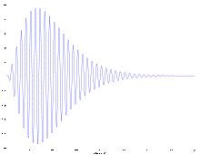
There are two ways to implement the timing measurements needed for a hyperbolic navigation system, pulse timing systems like Gee and LORAN, and phase-timing systems like the Decca Navigator System. The former requires sharp pulses of signal, and their accuracy is generally limited to how rapidly the pulses can be turned on and off, which is, in turn, a function of the carrier frequency. There is an ambiguity in the signal, the same measurements can be valid at two locations relative to the broadcasters, but in normal operation these are hundreds of kilometers apart so one possibility can be eliminated. The second system requires constant signals ("continuous wave") and is easy to use even at low frequencies. However, its signal is ambiguous over the distance of a wavelength, meaning there are hundreds of locations that will return the same signal, referred to as cells in Decca. This demands some other navigation method to be used in conjunction to pick which cell the receiver is within.[12]
Numerous efforts were made to provide some sort of secondary low-accuracy system that could be used with a phase-comparison system like Decca in order to resolve the ambiguity. Among the many methods were a directional broadcast systems known as POPI, and a variety of systems combining pulse-timing for low-accuracy navigation and then using phase-comparison for fine adjustment. Decca themselves had set aside one frequency, "9f", for testing this concept, but did not have the chance to do so until much later. Similar concepts were also used in the experimental Navarho system in the US.[13]
It was known from the start of the LORAN project that the same CRT displays that showed the LORAN pulses would also, when suitably magnified, show the individual waves of the intermediate frequency. This meant that pulse-matching could be used to get a rough fix, and then the operator could gain additional timing accuracy by lining up the individual waves within the pulse, like Decca. This could either be used to greatly increase the accuracy of LORAN, or alternately, offer similar accuracy using much lower carrier frequencies, and thus greatly extend range. This would require the transmitter stations to be synchronized both in time and phase, but much of this problem had been solved by Decca engineers.[12]
The long-range option was of considerable interest to the Coast Guard, who set up an experimental system known as LF LORAN in 1945. This operated at much lower frequencies than the original LORAN, 180 kHz, and required very long balloon-borne antennas. Testing was carried out throughout the year, including several long-distance flights as far as Brazil. The experimental system was then sent to Canada where it was used during Operation Muskox in the Arctic. Accuracy was found to be 150 feet (46 m) at 750 miles (1,210 km), a significant advance over LORAN. With the ending of Muskox it was decided to keep the system running under what became known as "Operation Musk Calf", run by a group consisting of the US Air Force, Royal Canadian Air Force, Royal Canadian Navy and Royal Corps of Signals. The system ran until September 1947.[14]
This led to another major test series, this time by the newly formed USAF, known as Operation Beetle. Beetle was located in the far north, on the Canada-Alaska border, and used new guy-stayed 625 feet (191 m) steel towers, replacing the earlier system's balloon-lofted cable antennas. The system became operational in 1948 and ran for two years until February 1950. Unfortunately the stations proved poorly sited, as the radio transmission over the permafrost was much shorter than expected and synchronization of the signals between the stations using groundwaves proved impossible. The tests also showed that the system was extremely difficult to use in practice; it was easy for the operator to select the wrong sections of the waveforms on their display, leading to significant real-world inaccuracy.[14]
CYCLAN and Whyn
In 1946 the Rome Air Development Center sent out contracts for longer-ranged and more-accurate navigation systems that would be used for long-range bombing navigation. As the US Army Air Force was moving towards smaller crews, only three in the Boeing B-47 Stratojet for instance, a high degree of automation was desired. Two contracts were accepted; Sperry Gyroscope proposed the CYCLAN system (CYCLe matching LorAN) which was broadly similar to LF LORAN but with additional automation, and Sylvania proposed Whyn using continuous wave navigation like Decca, but with additional coding using frequency modulation. In spite of great efforts, Whyn could never be made to work, and was abandoned.[15]
CYCLAN operated by sending the same LF LORAN-like signals on two frequencies, LF LORAN's 180 kHz and again on 200 kHz. The associated equipment would look for a rising amplitude that indicated the start of the signal pulse, and then use sampling gates to extract the carrier phase. Using two receivers solved the problem of mis-aligning the pulses, because the phases would only align properly between the two copies of the signal when the same pulses were being compared. None of this was trivial; using the era's tube-based electronics, the experimental CYCLAN system filled much of a semi-trailer.[16]
CYCLAN proved highly successful, so much so that it became increasingly clear that the problems that led the engineers to use two frequencies were simply not as bad as expected. It appeared that a system using a single frequency would work just as well, given the right electronics. This was especially good news, as the 200 kHz frequency was interfering with existing broadcasts, and had to be moved to 160 kHz during testing.[17]
Through this period the issue of radio spectrum use was becoming a major concern, and had led to international efforts to decide on a frequency band suitable for long-range navigation. This process eventually settled on the band from 90 to 100 kHz. CYCLAN appeared to suggest that accuracy at even lower frequencies was not a problem, and the only real concern was the expense of the equipment involved.[17]
Cytac
The success of the CYCLAN system led to a further contract with Sperry in 1952 for a new system with the twin goals of working in the 100 kHz range while being equally accurate, less complex and less expensive. These goals would normally be contradictory, but the CYCLAN system gave all involved the confidence that these could be met The resulting system was known as Cytac.[18]
To solve the complexity problem, a new circuit was developed to properly time the sampling of the signal. This consisted of a circuit to extract the envelope of the pulse, another to extract the derivative of the envelope, and finally another that subtracted the derivative from the envelope. The result of this final operation would become negative during a very specific and stable part of the rising edge of the pulse, and this zero-crossing was used to trigger a very short-time sampling gate. This system replaced the complex system of clocks used in CYCLAN. By simply measuring the time between the zero-crossings of the master and slave, pulse-timing was extracted.[19]
The output of the envelope sampler was also sent to a phase-shifter that adjusted the output of a local clock that locked to the master carrier using a phase-locked loop. This retained the phase of the master signal long enough for the slave signal to arrive. Gating on the slave signal was then compared to this master signal in a phase detector, and a varying voltage was produced depending on the difference in phase. This voltage represented the fine-positioning measurement.[19]
The system was generally successful during testing through 1953, but there were concerns raised about the signal power at long ranges, and the possibility of jamming. This led to further modifications of the basic signal. The first was to broadcast a series of pulses instead of just one, broadcasting more energy during a given time and improving the ability of the receivers to tune in a useful signal. They also added a fixed 45° phase shift to every pulse, so simple continuous-wave jamming signals could be identified and rejected.[20]
The Cytac system underwent an enormous series of tests across the United States and offshore. Given the potential accuracy of the system, even minor changes to the groundwave synchronization were found to cause errors that could be eliminated - issues such as the number of rivers the signal crossed caused predictable delays that could be measured and then factored into navigation solutions. This led to a series of correction contours that could be added to the received signal to adjust for these concerns, and these were printed on the Cytac charts. Using prominent features on dams as target points, a series of tests demonstrated that the uncorrected signals provided accuracy on the order of 100 yards, while adding the correction contour adjustments reduced this to the order of ten yards.[21]
Loran-B and -C
It was at this moment that the US Air Force (having taken over these efforts while moving from the USAAF) dropped their interest in the project. Although the reasons are not well recorded, it appears the idea of a fully automated bombing system using radio aids was no longer considered possible.[18] The AAF had been involved in missions covering about 1000 km (the distance from London to Berlin) and the Cytac system would work well at these ranges. But as the mission changed to trans-polar missions of 5,000 km or more, even Cytac did not offer the range and accuracy needed. They turned their attention to the use of inertial platforms and Doppler radar systems, cancelling work on Cytac as well as a competing system known as Navarho.[22]
Around this period the Navy began work on a similar system using combined pulse and phase comparison, but based on the existing LORAN frequency of 200 kHz. By this time the Navy had handed operational control of the LORAN system to the Coast Guard, and it was assumed the same arrangement would be true for any new system as well. Thus the Coast Guard was given the choice of naming the systems, and decided to rename the existing system Loran-A, and the new system Loran-B.[1]
With Cytac fully developed and its test system on the US east coast mothballed, the Navy also decided to re-commission Cytac for tests in the long-range role. An extensive series of tests across the Atlantic were carried out by the USCGC Androscoggin (WHEC-68) starting in April 1956. Meanwhile, Loran-B proved to have serious problems keeping their transmitters in phase, and that work was abandoned.[lower-alpha 2] Minor changes were made to the Cytac systems to further simplify it, including a reduction in the pulse-chain spacing from 1200 to 1000 µs, the pulse rate changed to 20 pps to match the existing Loran-A system, and the phase-shifting between pulses to an alternating 0, 180 degree shift instead of 45 degrees at every pulse within the chain.[23]
The result was Loran-C. Testing of the new system was intensive, and overwater flights around Bermuda demonstrated that 50% of fixes lay within a 260 foot (79 m) circle.[24] This was a dramatic improvement over the original Loran-A, meeting the accuracy of the Gee system but at much greater range. The first chain were set up using the original experimental Cytac system, along with a second in the Mediterranean in 1957. Further chains covering the North Atlantic and large areas of the Pacific followed. At the time global charts were printed with shaded sections representing the area where a 3 miles (4.8 km) accurate fix could be obtained under most operational conditions.
Improving systems
Loran-C had originally been designed to be highly automated, allowing the system to be operated more rapidly than the original LORAN's multi-minute measurement. It was also operated in "chains" of linked stations, allowing a fix to be made by simultaneously comparing two slaves to a single master. The downside of this approach was that the required electronic equipment, built using 1950s-era tube technology, was very large. Looking for companies with knowledge of seaborne, multi-channel phase-comparison electronics led, ironically, to Decca, who built the AN/SPN-31, the first widely used Loran-C receiver. The AN/SPN-31 weighed over 100 pounds (45 kg) and had 52 controls.[25]
Airborne units followed, and an adapted AN/SPN-31 was tested in an Avro Vulcan in 1963. By the mid-1960s, units with some transistorization were becoming more common, and a chain was set up in Viet Nam to support the US war efforts there. A number of commercial airline operators experimented with the system as well, using it for navigation on the great circle route between North America and Europe. However, inertial platforms ultimately became more common in this role.[25]
In 1969, Decca sued the Navy for patent infringement, producing ample documentation of their work on the basic concept as early as 1944, along with the "missing" 9f frequency[lower-alpha 3] at 98 kHz that had been set aside for experiments using this system. Decca won the initial suit, but the judgement was overturned on appeal when the Navy claimed "wartime expediency".[26]
Loran-D and -F
When Loran-C became widespread, the USAF once again became interested in using it as a guidance system. They proposed a new system layered on top of Loran-C, using it as the coarse guidance signal in much the same way that pulses were the coarse guidance and phase-comparison used for fine. To provide an extra-fine guidance signal, Loran-D interleaved another train of eight pulses immediately after the signals from one of the existing Loran-C stations, folding the two signals together. This technique became known as "Supernumary Interpulse Modulation" (SIM). These were broadcast from low-power portable transmitters, offering relatively short-range service of high accuracy.[27]
Loran-D was used only experimentally during war-games in the 1960s from a transmitter set in the UK. The system was also used in a limited fashion during the Vietnam War, combined with the Pave Spot laser designator system, a combination known as Pave Nail. Using mobile transmitters, the AN/ARN-92 LORAN navigation receiver could achieve accuracy on the order of 60 feet (18 m), which the Spot system improved to about 20 feet (6.1 m).[27] The SIM concept became a system for sending additional data.[28][29]
At about the same time, Motorola proposed a new system using pseudo-random pulse-chains. This mechanism ensures that no two chains within a given period (on the order of many seconds) will have the same pattern, making it easy to determine if the signal is a groundwave from a recent transmission or a multi-hop signal from a previous one. The system, Multi-User Tactical Navigation Systems (MUTNS) was used briefly but it was found that Loran-D met the same requirements but had the added advantage of being a standard Loran-C signal as well. Although MUTNS was unrelated to the Loran systems, it was sometimes referred to as Loran-F.[30]
Decline
In spite of its many advantages, the high cost of implementing a Loran-C receiver made it uneconomical for many users. Additionally, as military users upgraded from Loran-A to Loran-C, large numbers of surplus Loran-A receivers were dumped on the market. This made Loran-A popular in spite of being less accurate and fairly difficult to operate. By the early 1970s the introduction of integrated circuits combining a complete radio receiver began to greatly reduce the complexity of Loran-A measurements, and fully automated units the size of a stereo receiver became common. For those users requiring higher accuracy, Decca had considerable success with their Decca Navigator system, and produced units that combined both receivers, using Loran to eliminate the ambiguities in Decca.
The same rapid development of microelectronics that made Loran-A so easy to operate worked equally well on the Loran-C signals, and the obvious desire to have a long-range system that could also provide enough accuracy for lake and harbour navigation led to the "opening" of the Loran-C system to public use in 1974. Civilian receivers quickly followed, and dual-system A/C receivers were also common for a time. The switch from A to C was extremely rapid, due largely to rapidly falling prices which led to many users' first receiver being Loran-C. By the late 1970s the Coast Guard decided to turn off Loran-A, in favour of adding additional Loran-C stations to cover gaps is its coverage. The original Loran-A network was shut down in 1979 and 1980, with a few units used in the Pacific for some time. Given the widespread availability of Loran-A charts, many Loran-C receivers included a system for converting coordinates between A and C units.
One of the reasons for Loran-C's opening to the public was the move from Loran to new forms of navigation, including INS, Transit and OMEGA, meant that the security of Loran was no longer as stringent as it was as a primary form of navigation. As these newer systems gave way to GPS through the 1980s and 90s, this process repeated itself, but this time the military was able to separate GPS's signals in such a way that it could provide both secure military and insecure civilian signals at the same time. GPS was more difficult to receive and decode, but by the 1990s the required electronics were already as small and inexpensive as Loran-C, leading to rapid adoption that has become largely universal.
Loran-C today
Although Loran-C was largely redundant by 2000, it has not universally disappeared as of 2014 due to a number of concerns. One is that the GPS system can be jammed through a variety of means; although the same is true of Loran-C, the transmitters are close-at-hand and can be adjusted if need be. More importantly, there are effects that might cause the GPS system to become unusable over wide areas, notably space weather events and potential EMP events. Loran, located entirely under the atmosphere, offers more resilience to these sorts of issues. There has been considerable debate about the relative merits of keeping the Loran-C system operational as a result of considerations like these.
In November 2009, the USCG announced that Loran-C is not needed by the U.S. for maritime navigation. This decision left the fate of LORAN and eLORAN in the U.S. to the Secretary of the Department of Homeland Security.[31] Per a subsequent announcement, the U.S. Coast Guard, in accordance with the DHS Appropriations Act, terminated the transmission of all U.S. LORAN-C signals on 8 February 2010.[2] On 1 August 2010 the U.S. transmission of the Russian American signal was terminated,[2] and on 3 August 2010 all Canadian signals were shut down by the USCG and the CCG.[2][3]
The European Union had decided that the potential security advantages of Loran are worthy not only of keeping the system operational, but upgrading it and adding new stations. This is part of the wider Eurofix system which combines GPS, Galileo and nine Loran stations into a single integrated system.
However, in 2014, Norway and France both announced that all of their remaining transmitters, which make up a significant part of the Eurofix system, will be shut down on 31 December 2015.[32] The two remaining transmitters in Europe (Anthorn, UK and Sylt, Germany) will no longer be able to sustain a positioning and navigation Loran service, with the result that the UK announced its trial eLoran service would be discontinued from the same date.
Description
Hyperbolic navigation

In conventional navigation, measuring one's location, or taking a fix, is accomplished by taking two measurements against well known locations. In optical systems this is typically accomplished by measuring the angle to two landmarks, and then drawing lines on a nautical chart at those angles, producing an intersection that reveals the ship's location. Radio methods can also use the same concept with the aid of a radio direction finder, but due to the nature of radio propagation, such instruments are subject to significant errors, especially at night. More accurate radio navigation can be made using pulse timing or phase comparison techniques, which rely on the time-of-flight of the signals. In comparison to angle measurements, these remain fairly steady over time, and most of the effects that change these values are fixed objects like rivers and lakes that can be accounted for on charts.
Timing systems can reveal the absolute distance to an object, as is the case in radar. The problem in the navigational case is that the receiver has to know when the original signal was sent. In theory, one could synchronize an accurate clock to the signal before leaving port, and then use that to compare the timing of the signal during the voyage. However, in the 1940s no suitable system was available that could hold an accurate signal over the time span of an operational mission.
Instead, radio navigation systems adopted the multilateration concept. which is based on the difference in times (or phase) instead of the absolute time. The basic idea is that it is relatively easy to synchronize two ground stations, using a signal shared over a phone line for instance, so one can be sure that the signals received were sent at exactly the same time. They will not be received at exactly the same time, however, as the receiver will receive the signal from the closer station first. Timing the difference between two signals can be easily accomplished, first by physically measuring them on a cathode ray tube, or simple electronics in the case of phase comparison.
The difference in signal timing does not reveal the location by itself. Instead, it determines a series of locations where that timing is possible. For instance, if the two stations are 300 km apart and the receiver measures no difference in the two signals, that implies that the receiver is somewhere along a line equidistant between the two. If the signal from one is received exactly 100 µs, then the receiver is 30 kilometres (19 mi) closer to one station than the other. Plotting all the locations where one station is 30 km closer than the other produces a curved line. Taking a fix is accomplished by making two such measurements with different pairs of stations, and then looking up both curves on a navigational chart. The curves are known as lines of position or LOP.[33]
In practice, radio navigation systems normally use a chain of three or four stations, all synchronized to a master signal that is broadcast from one of the stations. The others, the secondaries, are positioned so their LOPs cross at acute angles, which increases the accuracy of the fix. So for instance, a given chain might have four stations with the master in the center, allowing a receiver to pick the signals from two secondaries that are currently as close to right angles as possible given their current location. Modern systems, which know the locations of all the broadcasters, can automate which stations to pick.
LORAN method
In the case of LORAN, one station remains constant in each application of the principle, the primary, being paired up separately with two other secondary stations. Given two secondary stations, the time difference (TD) between the primary and first secondary identifies one curve, and the time difference between the primary and second secondary identifies another curve, the intersections of which will determine a geographic point in relation to the position of the three stations. These curves are referred to as TD lines.[34]
In practice, LORAN is implemented in integrated regional arrays, or chains, consisting of one primary station and at least two (but often more) secondary stations, with a uniform group repetition interval (GRI) defined in microseconds. The amount of time before transmitting the next set of pulses is defined by the distance between the start of transmission of primary to the next start of transmission of primary signal.
The secondary stations receive this pulse signal from the primary, then wait a preset number of milliseconds, known as the secondary coding delay, to transmit a response signal. In a given chain, each secondary's coding delay is different, allowing for separate identification of each secondary's signal. (In practice, however, modern LORAN receivers do not rely on this for secondary identification.)
LORAN chains (GRIs)

Every LORAN chain in the world uses a unique Group Repetition Interval, the number of which, when multiplied by ten, gives how many microseconds pass between pulses from a given station in the chain. (In practice, the delays in many, but not all, chains are multiples of 100 microseconds.) LORAN chains are often referred to by this designation (e.g., GRI 9960, the designation for the LORAN chain serving the Northeast United States).
Due to the nature of hyperbolic curves, a particular combination of a primary and two secondary stations can possibly result in a "grid" where the grid lines intersect at shallow angles. For ideal positional accuracy, it is desirable to operate on a navigational grid where the grid lines are closer to right angles (orthogonal) to each other. As the receiver travels through a chain, a certain selection of secondaries whose TD lines initially formed a near-orthogonal grid can become a grid that is significantly skewed. As a result, the selection of one or both secondaries should be changed so that the TD lines of the new combination are closer to right angles. To allow this, nearly all chains provide at least three, and as many as five, secondaries.
LORAN charts
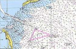
Where available, common marine nautical charts include visible representations of TD lines at regular intervals over water areas. The TD lines representing a given primary-secondary pairing are printed with distinct colors, and note the specific time difference indicated by each line. On a nautical chart, the denotation for each Line of Position from a receiver, relative to axis and color, can be found at the bottom of the chart. The color on official charts for stations and the timed-lines of position follow no specific conformance for the purpose of the International Hydrographic Organization (IHO). However, local chart producers may color these in a specific conformance to their standard. Always consult the chart notes, administrations Chart1 reference, and information given on the chart for the most accurate information regarding surveys, datum, and reliability.
There are three major factors when considering signal delay and propagation in relation to LORAN-C:
- Primary Phase Factor (PF) – This allows for the fact that the speed of the propagated signal in the atmosphere is slightly lower than in a vacuum.
- Secondary Phase Factor (SF) – This allows for the fact that the speed of propagation of the signal is slowed when traveling over the seawater because of the greater conductivity of seawater compared to land.
- Additional Secondary Factors (ASF) – Because LORAN-C transmitters are mainly land based, the signal will travel partly over land and partly over seawater. ASF may be treated as land and water segments, each with a uniform conductivity depending on whether the path is over land or water.
The chart notes should indicate whether ASF corrections have been made (Canadian Hydrographic Service (CHS) charts, for example, include them). Otherwise, the appropriate correction factors must be obtained before use.
Due to interference and propagation issues suffered from land features and artificial structures such as tall buildings, the accuracy of the LORAN signal can be degraded considerably in inland areas (see Limitations). As a result, nautical charts will not show TD lines in those areas, to prevent reliance on LORAN-C for navigation.
Traditional LORAN receivers display the time difference between each pairing of the primary and one of the two selected secondary stations, which is then used to find the appropriate TD line on the chart. Modern LORAN receivers display latitude and longitude coordinates instead of time differences, and, with the advent of time difference comparison and electronics, provide improved accuracy and better position fixing, allowing the observer to plot their position on a nautical chart more easily. When using such coordinates, the datum used by the receiver (usually WGS84) must match that of the chart, or manual conversion calculations must be performed before the coordinates can be used.
Timing and synchronization

Each LORAN station is equipped with a suite of specialized equipment to generate the precisely timed signals used to modulate / drive the transmitting equipment. Up to three commercial cesium atomic clocks are used to generate 5 MHz and pulse per second (or 1 Hz) signals that are used by timing equipment to generate the various GRI-dependent drive signals for the transmitting equipment.
While each U.S.-operated LORAN station is supposed to be synchronized to within 100 ns of UTC, the actual accuracy achieved as of 1994 was within 500 ns.[35]
Transmitters and antennas
LORAN-C transmitters operate at peak powers of 100–4,000 kilowatts, comparable to longwave broadcasting stations. Most use 190–220 metre tall mast radiators, insulated from ground. The masts are inductively lengthened and fed by a loading coil (see: electrical lengthening). A well known-example of a station using such an antenna is Rantum. Free-standing tower radiators in this height range are also used. Carolina Beach uses a free-standing antenna tower. Some LORAN-C transmitters with output powers of 1,000 kW and higher used supertall 412 metre mast radiators (see below). Other high power LORAN-C stations, like George, used four T-antennas mounted on four guyed masts arranged in a square.
All LORAN-C antennas are designed to radiate an omnidirectional pattern. Unlike longwave broadcasting stations, LORAN-C stations cannot use backup antennas because the exact position of the antenna is a part of the navigation calculation. The slightly different physical location of a backup antenna would produce Lines of Position different from those of the primary antenna.
Limitations
 Atlantic Ocean LORAN coverage (2006)
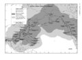 Pacific Ocean LORAN coverage (2006)
LORAN suffers from electronic effects of weather and the ionospheric effects of sunrise and sunset. The most accurate signal is the groundwave that follows the Earth's surface, ideally over seawater. At night the indirect skywave, bent back to the surface by the ionosphere, is a problem as multiple signals may arrive via different paths (multipath interference). The ionosphere's reaction to sunrise and sunset accounts for the particular disturbance during those periods. Magnetic storms have serious effects as with any radio based system.
LORAN uses ground based transmitters that only cover certain regions. Coverage is quite good in North America, Europe, and the Pacific Rim.
The absolute accuracy of LORAN-C varies from 0.10 to 0.25 nmi (185 to 463 m). Repeatable accuracy is much greater, typically from 60 to 300 ft (18 to 91 m).[36]
LORAN Data Channel (LDC)
LORAN Data Channel (LDC) is a project underway between the FAA and USCG to send low bit rate data using the LORAN system. Messages to be sent include station identification, absolute time, and position correction messages. In 2001, data similar to Wide Area Augmentation System (WAAS) GPS correction messages were sent as part of a test of the Alaskan LORAN chain. As of November 2005, test messages using LDC were being broadcast from several U.S. LORAN stations.
In recent years, LORAN-C has been used in Europe to send differential GPS and other messages, employing a similar method of transmission known as EUROFIX.
A system called SPS (Saudi Positioning System), similar to EUROFIX, is in use in Saudi Arabia.[37] GPS differential corrections and GPS integrity information are added to the LORAN signal. A combined GPS/LORAN receiver is used, and if a GPS fix is not available it automatically switches over to LORAN.
The future of LORAN
As LORAN systems are government maintained and operated, their continued existence is subject to public policy. With the evolution of other electronic navigation systems, such as satellite navigation systems, funding for existing systems is not always assured.
Critics, who have called for the elimination of the system, state that the LORAN system has too few users, lacks cost-effectiveness, and that GNSS signals are superior to LORAN. Supporters of continued and improved LORAN operation note that LORAN uses a strong signal, which is difficult to jam, and that LORAN is an independent, dissimilar, and complementary system to other forms of electronic navigation, which helps ensure availability of navigation signals.[38][39]
On 26 February 2009, the U.S. Office of Management and Budget released the first blueprint for the Financial Year 2010 budget.[40] This document identified the LORAN-C system as “outdated” and supported its termination at an estimated savings of $36 million in 2010 and $190 million over five years.
On 21 April 2009 the U.S. Senate Committee on Commerce, Science and Transportation and the Committee on Homeland Security and Governmental Affairs released inputs to the FY 2010 Concurrent Budget Resolution with backing for the continued support for the LORAN system, acknowledging the investment already made in infrastructure upgrades and recognizing the studies performed and multi-departmental conclusion that eLORAN is the best backup to GPS.
Senator Jay Rockefeller, Chairman of the Committee on Commerce, Science and Transportation, wrote that the committee recognized the priority in "Maintaining LORAN-C while transitioning to eLORAN" as means of enhancing the homeland security, marine safety and environmental protection missions of the Coast Guard.
Senator Collins, the ranking member on the Committee on Homeland Security and Governmental Affairs wrote that the President's budget overview proposal to terminate the LORAN-C system is inconsistent with the recent investments, recognized studies and the mission of the U.S. Coast Guard. The committee also recognizes the $160 million investment already made toward upgrading the LORAN-C system to support the full deployment of eLORAN.
Further, the Committees also recognize the many studies which evaluated GPS backup systems and concluded both the need to back up GPS and identified eLORAN as the best and most viable backup. "This proposal is inconsistent with the recently released (January 2009) Federal Radionavigation Plan (FRP), which was jointly prepared by DHS and the Departments of Defense (DOD) and Transportation (DOT). The FRP proposed the eLORAN program to serve as a Position, Navigation and Timing (PNT) backup to GPS (Global Positioning System)."
On 7 May 2009, President Barack Obama proposed cutting funding (approx. $35 million/year) for LORAN, citing its redundancy alongside GPS.[41] In regard to the pending Congressional bill, H.R. 2892, it was subsequently announced that "[t]he Administration supports the Committee's aim to achieve an orderly termination through a phased decommissioning beginning in January 2010, and the requirement that certifications be provided to document that the LORAN-C termination will not impair maritime safety or the development of possible GPS backup capabilities or needs."[42]
Also on 7 May 2009, the U.S. General Accounting Office (GAO), the investigative arm of Congress, released a report citing the very real potential for the GPS system to degrade or fail in light of program delays which have resulted in scheduled GPS satellite launches slipping by up to three years.[43]
On 12 May 2009 the March 2007 Independent Assessment Team (IAT) report on LORAN was released to the public. In its report the ITA stated that it "unanimously recommends that the U.S. government complete the eLORAN upgrade and commit to eLORAN as the national backup to GPS for 20 years." The release of the report followed an extensive Freedom Of Information Act (FOIA) battle waged by industry representatives against the federal government. Originally completed 20 March 2007 and presented to the co-sponsoring Department of Transportation and Department of Homeland Security (DHS) Executive Committees, the report carefully considered existing navigation systems, including GPS. The unanimous recommendation for keeping the LORAN system and upgrading to eLORAN was based on the team's conclusion that LORAN is operational, deployed and sufficiently accurate to supplement GPS. The team also concluded that the cost to decommission the LORAN system would exceed the cost of deploying eLORAN, thus negating any stated savings as offered by the Obama administration and revealing the vulnerability of the U.S. to GPS disruption.[44]
In November 2009, the U.S. Coast Guard announced that the LORAN-C stations under its control would be closed down for budgetary reasons after 4 January 2010 provided the Secretary of the Department of Homeland Security certified that LORAN is not needed as a backup for GPS.[45]
On 7 January 2010, Homeland Security published a notice of the permanent discontinuation of LORAN-C operation. Effective 2000 UTC 8 February 2010, the United States Coast Guard terminated all operation and broadcast of LORAN-C signals in the USA. The U.S. Coast Guard transmission of the Russian American CHAYKA signal was terminated on 1 August 2010. The transmission of Canadian LORAN-C signals was terminated on 3 August 2010.[46]
eLORAN
With the perceived vulnerability of GNSS systems,[47] and their own propagation and reception limitations, renewed interest in LORAN applications and development has appeared.[48] Enhanced LORAN, also known as eLORAN or E-LORAN, comprises an advancement in receiver design and transmission characteristics which increase the accuracy and usefulness of traditional LORAN. With reported accuracy as good as ± 8 meters,[49] the system becomes competitive with unenhanced GPS. eLORAN also includes additional pulses which can transmit auxiliary data such as DGPS corrections. eLORAN receivers now use "all in view" reception, incorporating signals from all stations in range, not solely those from a single GRI, incorporating time signals and other data from up to 40 stations. These enhancements in LORAN make it adequate as a substitute for scenarios where GPS is unavailable or degraded.[50]
United Kingdom eLORAN implementation
On 31 May 2007, the UK Department for Transport (DfT), via the General Lighthouse Authorities (GLA), awarded a 15-year contract to provide a state-of-the-art enhanced LORAN (eLORAN) service to improve the safety of mariners in the UK and Western Europe. The service contract will operate in two phases, with development work and further focus for European agreement on eLORAN service provision from 2007 through 2010, and full operation of the eLORAN service from 2010 through 2022. The first eLORAN transmitter is situated at Anthorn radio station Cumbria, UK, and operated by Babcock Comms, which is part of the Babcock Group PLC.[51]
eLORAN: The UK government has granted approval for seven differential eLoran ship-positioning technology stations to be built along the south and east coasts of the UK to help counter the threat of jamming of global positioning systems. They are set to reach initial operational capability by summer 2014.[52] The General Lighthouse Authorities (GLAs) of the UK and Ireland announced October 31 the initial operational capability of UK maritime eLoran. Seven differential reference stations now provide additional position, navigation, and timing (PNT) information via low-frequency pulses to ships fitted with eLoran receivers. The service will help ensure they can navigate safely in the event of GPS failure in one of the busiest shipping regions in the world, with expected annual traffic of 200,000 vessels by 2020.[53]
Despite these plans, in light of the decision by France and Norway to cease Loran transmissions on 31 December 2015, the UK announced at the start of that month that its eLoran service would be discontinued on the same day.[54]
List of LORAN-C transmitters

A list of LORAN-C transmitters. Stations with an antenna tower taller than 300 metres (984 feet) are shown in bold.
| Station | Country | Chain | Coordinates | Remarks |
|---|---|---|---|---|
| Afif | Saudi Arabia | Saudi Arabia South (GRI 7030) Saudi Arabia North (GRI 8830) | 23°48′36.66″N 42°51′18.17″E / 23.8101833°N 42.8550472°E | 400 kW |
| Al Khamasin | Saudi Arabia | Saudi Arabia South (GRI 7030) Saudi Arabia North (GRI 8830) | 20°28′2.34″N 44°34′51.9″E / 20.4673167°N 44.581083°E | |
| Al Muwassam | Saudi Arabia | Saudi Arabia South (GRI 7030) Saudi Arabia North (GRI 8830) | 16°25′56.87″N 42°48′6.21″E / 16.4324639°N 42.8017250°E | |
| Angissq | Greenland | Shut down on 31 December 1994 | 59°59′17.348″N 45°10′26.91″W / 59.98815222°N 45.1741417°W | used until 27 July 1964 a 411.48 metre tower |
| Anthorn | United Kingdom | Lessay (GRI 6731) | 54°54′41.949″N 3°16′42.58″W / 54.91165250°N 3.2784944°W | Master and Slave on 9 Jan. 2016. Replacement for transmitter Rugby[55] |
| Ash Shaykh Humayd | Saudi Arabia | Saudi Arabia South (GRI 7030) Saudi Arabia North (GRI 8830) | 28°9′15.87″N 34°45′41.36″E / 28.1544083°N 34.7614889°E | |
| Attu Island | United States | North Pacific (GRI 9990) Russian-American (GRI 5980) | 52°49′44″N 173°10′49.7″E / 52.82889°N 173.180472°E | demolished in August 2010 |
| Balasore | India | Calcutta (GRI 5543) | 21°29′11.02″N 86°55′9.66″E / 21.4863944°N 86.9193500°E | |
| Barrigada | Guam | shut down | 13°27′50.16″N 144°49′33.4″E / 13.4639333°N 144.825944°E | |
| Baudette | United States | North Central U.S. (GRI 8290) Great Lakes (GRI 8970) | 48°36′49.947″N 94°33′17.91″W / 48.61387417°N 94.5549750°W | |
| Berlevåg | Norway | Bø (GRI 7001) | 70°50′43.07″N 29°12′16.04″E / 70.8452972°N 29.2044556°E | |
| Bilimora | India | Bombay (GRI 6042) | 20°45′42.036″N 73°02′14.48″E / 20.76167667°N 73.0373556°E | |
| Boise City | United States | Great Lakes (GRI 8970) South Central U.S. (GRI 9610) | 36°30′20.75″N 102°53′59.4″W / 36.5057639°N 102.899833°W | |
| Bø, Vesterålen | Norway | Bø (GRI 7001) Eiði (GRI 9007) | 68°38′06.216″N 14°27′47.35″E / 68.63506000°N 14.4631528°E | |
| Cambridge Bay | Canada | shut down | 69°06′52.840″N 105°00′55.95″W / 69.11467778°N 105.0155417°W | free-standing lattice tower, used as NDB |
| Cape Race | Canada | Canadian East Coast (GRI 5930) Newfoundland East Coast (GRI 7270) | 46°46′32.74″N 53°10′28.66″W / 46.7757611°N 53.1746278°W | used a 411.48 metre tall tower until 2 February 1993, uses now a 260.3 metre tall tower |
| Caribou, Maine | United States | Canadian East Coast (GRI 5930) Northeast U.S. (GRI 9960) | 46°48′27.305″N 67°55′37.15″W / 46.80758472°N 67.9269861°W | |
| Carolina Beach | United States | Southeast U.S. (GRI 7980) Northeast US (GRI 9960) | 34°03′46.208″N 77°54′46.10″W / 34.06283556°N 77.9128056°W | |
| Chongzuo | China | China South Sea (GRI 6780) | 22°32′35.8″N 107°13′19″E / 22.543278°N 107.22194°E | |
| Comfort Cove | Canada | Newfoundland East Coast (GRI 7270) | 49°19′53.65″N 54°51′43.2″W / 49.3315694°N 54.862000°W | |
| Dana | United States | Great Lakes (GRI 8970) Northeast US (GRI 9960) | 39°51′7.64″N 87°29′10.71″W / 39.8521222°N 87.4863083°W | |
| Dhrangadhra | India | Bombay (GRI 6042) | 23°0′16.2″N 71°31′37.64″E / 23.004500°N 71.5271222°E | |
| Diamond Harbor | India | Calcutta (GRI 5543) | 22°10′20.42″N 88°12′15.8″E / 22.1723389°N 88.204389°E | |
| Eiði | Faroe Islands | Eiði (GRI 9007) | 62°17′59.69″N 7°4′25.59″W / 62.2999139°N 7.0737750°W | |
| Estartit | Spain | Mediterranean Sea (GRI 7990) (shut down) | 42°3′36.63″N 3°12′16.08″E / 42.0601750°N 3.2044667°E | |
| Fallon | United States | U.S. West Coast (GRI 9940) | 39°33′6.77″N 118°49′55.6″W / 39.5518806°N 118.832111°W | |
| Fox Harbour | Canada | Canadian East Coast (GRI 5930) Newfoundland East Coast (GRI 7270) | 52°22′35.29″N 55°42′28.68″W / 52.3764694°N 55.7079667°W | |
| George | United States | Canadian West Coast (GRI 5990) | 47°03′48.096″N 119°44′38.97″W / 47.06336000°N 119.7441583°W | |
| Gesashi | Japan | North West Pacific (GRI 8930) East Asia (GRI 9930) | 26°36′25.09″N 128°8′56.94″E / 26.6069694°N 128.1491500°E | |
| Gillette | United States | North Central U.S. (GRI 8290) South Central U.S. (GRI 9610) | 44°0′11.21″N 105°37′24″W / 44.0031139°N 105.62333°W | |
| Grangeville | United States | Southeast U.S. (GRI 7980) South Central U.S. (GRI 9610) | 30°43′33.24″N 90°49′43.01″W / 30.7259000°N 90.8286139°W | |
| Havre | United States | North Central U.S. (GRI 8290) | 48°44′38.58″N 109°58′53.3″W / 48.7440500°N 109.981472°W | |
| Hellissandur | Iceland | shut down on 31 December 1994 | 64°54′14.793″N 23°54′47.83″W / 64.90410917°N 23.9132861°W | 411.48 metre tall tower, now used for longwave broadcasting of RÚV on 189 kHz |
| Helong | China | China North Sea (GRI 7430) | 42°43′11″N 129°6′27.07″E / 42.71972°N 129.1075194°E | |
| Hexian | China | China South Sea (GRI 6780) | 23°58′3.21″N 111°43′9.78″E / 23.9675583°N 111.7193833°E | |
| Iwo Jima | Japan | shut down in September 1993. Dismantled | 24°48′26.262″N 141°19′34.76″E / 24.80729500°N 141.3263222°E | used a 411.48 metre tall tower |
| Jan Mayen | Norway | Bø (GRI 7001) Ejde (GRI 9007) | 70°54′51.478″N 8°43′56.52″W / 70.91429944°N 8.7323667°W | |
| Johnston Island | United States | shut down | 16°44′43.82″N 169°30′30.9″W / 16.7455056°N 169.508583°W | |
| Jupiter | United States | Southeast U.S. (GRI 7980) | 27°1′58.49″N 80°6′52.83″W / 27.0329139°N 80.1146750°W | |
| Kargaburun | Turkey | Mediterranean Sea (GRI 7990) (shut down) | 40°58′20.51″N 27°52′1.89″E / 40.9723639°N 27.8671917°E | |
| Kwang Ju | South Korea | East Asia (GRI 9930) | 35°2′23.69″N 126°32′27.2″E / 35.0399139°N 126.540889°E | |
| Lampedusa | Italy | Mediterranean Sea (GRI 7990) (shut down) | 35°31′22.11″N 12°31′31.06″E / 35.5228083°N 12.5252944°E | |
| Las Cruces | United States | South Central U.S. (GRI 9610) | 32°4′18.1″N 106°52′4.32″W / 32.071694°N 106.8678667°W | |
| Lessay | France | Shut down on 31 December 2015 Lessay (GRI 6731) Sylt (GRI 7499) | 49°8′55.27″N 1°30′17.03″W / 49.1486861°N 1.5047306°W | |
| Loop Head | Ireland | Lessay (GRI 6731) Eiði (GRI 9007) | (Never built) | 250 kW |
| Malone | United States | Southeast U.S. (GRI 7980) Great Lakes (GRI 8970) | 30°59′38.87″N 85°10′8.71″W / 30.9941306°N 85.1690861°W | |
| Middletown | United States | U.S. West Coast (GRI 9940) | 38°46′57.12″N 122°29′43.9″W / 38.7825333°N 122.495528°W | |
| Minamitorishima | Japan | North West Pacific (GRI 8930) | 24°17′8.79″N 153°58′52.2″E / 24.2857750°N 153.981167°E | used until 1985 a 411.48 metre tall tower |
| Nantucket | United States | Canadian East Coast (GRI 5930) Northeast U.S. (GRI 9960) | 41°15′12.42″N 69°58′38.73″W / 41.2534500°N 69.9774250°W | |
| Narrow Cape | United States | Gulf of Alaska (GRI 7960) North Pacific (GRI 9990) | 57°26′20.5″N 152°22′10.2″W / 57.439028°N 152.369500°W | |
| Niijima | Japan | North West Pacific (GRI 8930) East Asia (GRI 9930) | 34°24′12.06″N 139°16′19.4″E / 34.4033500°N 139.272056°E | |
| Patapur | India | Calcutta (GRI 5543) | 20°26′50.627″N 85°49′38.67″E / 20.44739639°N 85.8274083°E | |
| Pohang | South Korea | North West Pacific (GRI 8930) East Asia (GRI 9930) | 36°11′5.33″N 129°20′27.4″E / 36.1848139°N 129.340944°E | |
| Port Clarence | United States | Gulf of Alaska (GRI 7960) North Pacific (GRI 9990) | 65°14′40.372″N 166°53′11.996″W / 65.24454778°N 166.88666556°W | uses a 411.48 metre tall tower Demolished 28 April 2010 [56] |
| Port Hardy | Canada | Canadian West Coast (GRI 5990) | 50°36′29.830″N 127°21′28.48″W / 50.60828611°N 127.3579111°W | |
| Rantum (Sylt) | Germany | Shut down on 31 December 2015 Lessay (GRI 6731) Sylt (GRI 7499) | 54°48′29.94″N 8°17′36.9″E / 54.8083167°N 8.293583°E | |
| Raymondville | United States | Southeast U.S. (GRI 7980) South Central U.S. (GRI 9610) | 26°31′55.17″N 97°49′59.52″W / 26.5319917°N 97.8332000°W | |
| Raoping | China | China South Sea (GRI 6780) China East Sea (GRI 8390) | 23°43′26.02″N 116°53′44.7″E / 23.7238944°N 116.895750°E | |
| Rongcheng | China | China North Sea (GRI 7430) China East Sea (GRI 8390) | 37°03′51.765″N 122°19′25.95″E / 37.06437917°N 122.3238750°E | |
| Rugby | United Kingdom | Experimental (GRI 6731) (shut down at the end of July 2007) | 52°21′57.893″N 1°11′27.39″W / 52.36608139°N 1.1909417°W | |
| Saint Paul | United States | North Pacific (GRI 9990) | 57°9′12.35″N 170°15′6.06″W / 57.1534306°N 170.2516833°W | |
| Salwa | Saudi Arabia | Saudi Arabia South (GRI 7030) Saudi Arabia North (GRI 8830) | 24°50′1.46″N 50°34′12.54″E / 24.8337389°N 50.5701500°E | |
| Searchlight | United States | South Central U.S. (GRI 9610) U.S. West Coast (GRI 9940) | 35°19′18.305″N 114°48′16.88″W / 35.32175139°N 114.8046889°W | |
| Sellia Marina | Italy | Mediterranean Sea (GRI 7990) (shut down) | 38°52′20.72″N 16°43′6.27″E / 38.8724222°N 16.7184083°E | |
| Seneca | United States | Great Lakes (GRI 8970) Northeast U.S. (GRI 9960) | 42°42′50.716″N 76°49′33.30″W / 42.71408778°N 76.8259167°W | |
| Shoal Cove | United States | Canadian West Coast (GRI 5990) Gulf of Alaska (GRI 7960) | 55°26′20.940″N 131°15′19.09″W / 55.43915000°N 131.2553028°W | |
| Soustons | France | Shut down on 31 December 2015 Lessay (GRI 6731) | 43°44′23.21″N 1°22′49.63″W / 43.7397806°N 1.3804528°W | |
| Tok | United States | Gulf of Alaska (GRI 7960) | 63°19′42.884″N 142°48′31.34″W / 63.32857889°N 142.8087056°W | |
| Tokachibuto | Japan | Eastern Russia Chayka (GRI 7950) North West Pacific (GRI 8930) | 42°44′37.2″N 143°43′10.5″E / 42.743667°N 143.719583°E | |
| Upolo Point | United States | shut down | 20°14′51.12″N 155°53′4.34″W / 20.2475333°N 155.8845389°W | |
| Værlandet | Norway | Sylt (GRI 7499) Ejde (GRI 9007) | 61°17′49.49″N 4°41′47.05″E / 61.2970806°N 4.6964028°E | |
| Veraval | India | Bombay (GRI 6042) | 20°57′09.316″N 70°20′11.73″E / 20.95258778°N 70.3365917°E | |
| Williams Lake | Canada | Canadian West Coast (GRI 5990) North Central U.S. (GRI 8290) | 51°57′58.78″N 122°22′1.55″W / 51.9663278°N 122.3670972°W | |
| Xuancheng | China | China North Sea (GRI 7430) China East Sea (GRI 8390) | 31°4′8.3″N 118°53′8.78″E / 31.068972°N 118.8857722°E | |
| Yap | Federated States of Micronesia | shut down in 1987. Dismantled | 9°32′44.76″N 138°9′53.48″E / 9.5457667°N 138.1648556°E | used a 304.8 metre tall tower |
See also
- CHAYKA, the Russian counterpart of LORAN
- Alpha, the Russian counterpart of the Omega Navigation System, still in use as of 2006.
- OMEGA, the Western counterpart of the Alpha Navigation System, no longer in use.
- Decca Navigator System, a British system that used phase difference instead of time difference.
- SHORAN
- Oboe (navigation)
- G-H (navigation)
- GEE (navigation)
- GPS
- Local positioning system
Notes
- ↑ The original system was known as LORAN, a short-form for LOng RAnge Navigation. Operation of the system, and the newly introduced Loran-C system, were handed to the Coast Guard in 1958. They took the time to retroactively change the name of the original system to Loran-A, and used lower-case naming from then on.[1]
- ↑ Very little information on Loran-B is available in the public record, and any reasons for its failure even less so.
- ↑ Blanchard uses 7f and 9f on different pages.
References
Citations
- 1 2 Hefley 1972, p. xi..
- 1 2 3 4 "LORAN-C General Information". United States Coast Guard. Retrieved 4 August 2010.
- 1 2 "Termination of the Loran-C Service". notmar.gc.ca. Retrieved 4 August 2010. (for access click on "I have read..." and "Accept")
- ↑ "Loran off air in most of Europe move to commercial possible". Resilient Navigation and Timing Foundation. January 4, 2016.
- ↑ Divis, Dee Ann (December 10, 2015). "PNT ExCom Backs eLoran as a Step to Full GPS Backup System". Inside GNSS, (January/February 2016).
- ↑ "Will fund eLoran on a chip - NIST". Resilient Navigation and Timing Foundation. February 11, 2016.
- ↑ Halford, Davidson & Waldschmitt 1948, p. 19.
- ↑ Halford, Davidson and Waldschmitt, "History of LORAN", MIT Radiation Laboratory, pp. 19-23.
- ↑ Blanchard 1991, pp. 305–306.
- 1 2 Halford, Davidson & Waldschmitt 1948, p. 22.
- ↑ Hefley 1972, p. xi.
- 1 2 Blanchard 1991, pp. 302-303.
- ↑ Blanchard 1991, p. 302.
- 1 2 Hefley 1972, p. 16.
- ↑ Hefley 1972, pp. 19-20.
- ↑ Hefley 1972, pp. 20-21.
- 1 2 Hefley 1972, pp. 23-24.
- 1 2 Hefley 1972, pp. 25.
- 1 2 Hefley 1972, pp. 26.
- ↑ Hefley 1972, pp. 33.
- ↑ Hefley 1972, pp. 58.
- ↑ Gil McElroy, "Loran-C History'
- ↑ Hefley 1972, pp. 72.
- ↑ Hefley 1972, pp. 78.
- 1 2 Blanchard 1991, p. 310.
- ↑ Blanchard 1991, p. 311.
- 1 2 George Galdorisi and Thomas Phillips, "Leave No Man Behind", MBI Publishing, 2009, pg. 391.
- ↑ James Caffery, "Wireless Location in CDMA Cellular Radio Systems", Springer, 2000, pg. 5.
- ↑ Darrel Whitcomb, "PAVE NAIL: there at the beginning of the precision weapons revolutions"
- ↑ "Proceedings of the Eleventh Annual Technical Symposium", pg. 7.
- ↑ Senate committee letter Archived 12 December 2009 at the Wayback Machine.
- ↑ http://kartverket.no/efs-documents/editions/2015/efs01-2015.pdf, page 26
- ↑ Appleyard, S.F.; Linford, R.S.; Yarwood, P.J. (1988). Marine Electronic Navigation (2nd Edition). Routledge & Kegan Paul. pp. 77–83. ISBN 0-7102-1271-2.
- ↑ The American Practical Navigator, An Epitome of Navigation, page 173 Archived 1 December 2009 at the Wayback Machine.
- ↑ "Chapter 2 ̣– LORAN-C Transmissions" (PDF). Specification of the Transmitted LORAN-C Signal / COMDTINST M16562.4A. U.S. Coast Guard. 1994. pp. 6, 7. Retrieved 4 September 2012.
- ↑ COMDTPUB P16562.6, "LORAN-C Users Handbook", 1992
- ↑ "A New Navigation Positioning System run by Saudi Ports Authority". Saudi Ports Authority. 2006. Archived from the original on 10 February 2011. Retrieved 21 January 2011.
- ↑ "Enhanced Loran (eloran) Definition Document" (PDF). International Loran Association. 16 October 2007. Retrieved 18 July 2010.
- ↑ "GPS back-up 'needs more research' ". bbc.co.uk, 20 June 2008, Retrieved 5 October 2010
- ↑ Office of Management and Budget. ( www.budget.gov), "A New Era of Responsibility Renewing America's Promise" The FY 2010 Budget, Department of Homeland Security Section, page 72
- ↑ Obama: Budget cuts add up to 'real money'
- ↑ "H.R. 2892--Department of Homeland Security Appropriations Act, 2010". C-SPAN.org. 8 July 2009. Retrieved 10 August 2009.
- ↑ http://www.gao.gov/products/GAO-09-670T
- ↑ http://sidt.gpsworld.com/gpssidt/article/articleDetail.jsp?id=597861
- ↑ "USCG LORAN Program Manager release, Nov. 2009". 31 May 2007. Retrieved 28 November 2009.
- ↑ http://www.navcen.uscg.gov/?pageName=loranMain
- ↑ http://news.bbc.co.uk/2/hi/science/nature/8533157.stm
- ↑ "GPS vulnerable to hacker attacks". BBC News. 23 February 2010. Retrieved 11 May 2010.
- ↑ "GPS Backup: Is eLoran the answer?". Aviation Today. April 2012.
- ↑ Press office (7 February 2008). "Statement from DHS press secretary Laura Keehhner on the adoption of national backup system to GPS" (PDF). press release. United States Department of Homeland Security. Retrieved 10 January 2013.
- ↑ "The GLAs award a 15-year eLORAN contract to Babcock Communications". Trinity House. 31 May 2007. Archived from the original on 19 March 2011. Retrieved 27 May 2010.
- ↑ Nautilus International Newspaper August 2013
- ↑ GPS World. December 2014.
- ↑ "Notice To Mariners". Trinity House. 1 December 2015. Archived from the original on 4 March 2016. Retrieved 30 December 2015.
- ↑ "Electronic Position Fixing System" (PDF). Admiralty Notices to Mariners. United Kingdom Hydrographic Office (26/07). 28 June 2007. Archived from the original (– Scholar search) on 24 June 2008. Retrieved 19 January 2008.
- ↑ http://coastguardnews.com/video-loran-station-port-clarence-tower-demolition/2010/05/01/
Bibliography
- Department of Transportation and Department of Defense (February 2006). "2005 Federal Radionavigation Plan" (PDF). Retrieved 26 February 2006.
- Hefley, Gifford (1972). The Development of Loran-C Navigation and Timing. National Bureau of Standards.
- Blanchard, W. F. (September 1991). "Hyperbolic Airborne Radio Navigation Aids". Journal of Navigation: 285–315.
- L. E. Gatterer "The Development of Loran-C Navigation and Timing", National Bureau of Standards, October 1972
- Jennet Conant, Tuxedo Park: A Wall Street Tycoon and the Secret Palace of Science That Changed the Course of World War II (New York: Simon & Schuster, 2002, ISBN 0-684-87287-0) pp. 231–232.
- Halford, J. H.; Davidson, D.; Waldschmitt, J. A. (1948). "History of LORAN" (PDF). In Pierce, J. A.; McKenzie, A. A.; Woodward, R. H. LORAN: Long Range Navigation. New York: McGraw Hill. pp. 19–51..
External links
| Wikimedia Commons has media related to Loran-C. |
- International Loran Association
- United States National Institute of Standards and Technology Site- Using LORAN C for time-keeping.
- European Loran-C network website
- LORAN-C Transmitter (Rantum) at Structurae
- Hellissandur Transmission Tower at Structurae :former LORAN-C transmitter mast, now used for longwave broadcasting
- LORAN-C facility antenna (Gillette, Wyoming) at Structurae
- LORAN-C facility antenna (Port Clarence, Alaska) at Structurae
- Jerry Proc, VE3FAB: Hyperbolic Radionavigation Systems:
- Integrated GPS/Loran Prototypes for Aviation Applications
- The Migration to Enhanced or eLoran
- GNSS/eLoran for Timing and Frequency by Locus, Inc.
- Loran's Capability to Mitigate the Impact of a GPS Outage on GPS Position, Navigation, and Time Applications by Locus, Inc.
- New Potential of Low-Frequency Radionavigation in the 21st Century Ph.D. dissertation
- LORAN-C chains in service
- List of active LORAN-C transmitters
- SDR in action: The last LORAN-C receiver is a technical description of using a software-defined radio to decode LORAN-C signals
- New UK eLORAN service provision news article News article re: UK leading the way in eLORAN service provision.
- eLORAN vs Loran-C at Inside GNSS—Short article describing the innovations in eLORAN
- History of LORAN
- Dr. G. Linn Roth (October 1998). "The Case for Loran". International Loran Association. Retrieved 18 July 2010.