Ion thruster
An ion thruster is a form of electric propulsion used for spacecraft propulsion. It creates thrust by accelerating ions with electricity. The term refers strictly to gridded electrostatic ion thrusters, but may more loosely be applied to all electric propulsion systems that accelerate plasma, since plasma consists of ions.
Ion thrusters are categorized by how they accelerate the ions, using either electrostatic or electromagnetic force. Electrostatic thrusters use the Coulomb force and accelerate the ions in the direction of the electric field. Electromagnetic thrusters use the Lorentz force. In either case, when an ion passes through an electrostatic grid engine, the potential difference of the electric field converts to the ion's kinetic energy.
Ion thrusters have an input power need of 1–7 kW, exhaust velocity 20–50 km/s, thrust 25–250 millinewtons and efficiency 65–80%.[1][2]
The Deep Space 1 spacecraft, powered by an ion thruster, changed velocity by 4.3 km/s while consuming less than 74 kilograms of xenon. The Dawn spacecraft broke the record, reaching 10 km/s.[1][2]
Applications include control of the orientation and position of orbiting satellites (some satellites have dozens of low-power ion thrusters) and use as a main propulsion engine for low-mass robotic space vehicles (for example Deep Space 1 and Dawn).[1][2]
The ion thruster is not the most promising type of electrically powered spacecraft propulsion (although the most successful in practice).[2] An ion drive would require two days to accelerate a car to highway speed. The technical characteristics, especially thrust, are considerably inferior to the prototypes described in literature,[1][2] technical capabilities are limited by the space charge created by ions. This limits the thrust density (force per cross-sectional area of the engine).[2] Ion thrusters create small thrust levels (the thrust of Deep Space 1 is approximately equal to the weight of one sheet of paper[2]) compared to conventional chemical rockets, but achieve high specific impulse, or propellant mass efficiency, by accelerating the exhaust to high speed. The power imparted to the exhaust increases with the square of exhaust velocity while thrust increase is linear. Conversely, chemical rockets provide high thrust, but are limited in total impulse by the small amount of energy that can be stored chemically in the propellants.[3] Given the practical weight of suitable power sources, the acceleration from an ion thruster is frequently less than one thousandth of standard gravity. However, since they operate as electric (or electrostatic) motors, they convert a greater fraction of input power into kinetic exhaust power. Chemical rockets operate as heat engines, and Carnot's theorem limits the exhaust velocity.
Ion thrust engines are practical only in the vacuum of space and cannot take vehicles through the atmosphere because ion engines do not work in the presence of ions outside the engine. Spacecraft rely on conventional chemical rockets to initially reach orbit.
Origins

The first person to mention the idea publicly was Konstantin Tsiolkovsky in 1911.[4] However, the first document to consider electric propulsion is Robert H. Goddard's handwritten notebook in an entry dated September 6, 1906.[5] The first experiments with ion thrusters were carried out by Goddard at Clark University from 1916–1917.[6] The technique was recommended for near-vacuum conditions at high altitude, but thrust was demonstrated with ionized air streams at atmospheric pressure. The idea appeared again in Hermann Oberth's "Wege zur Raumschiffahrt” (Ways to Spaceflight), published in 1923, where he explained his thoughts on the mass savings of electric propulsion, predicted its use in spacecraft propulsion and attitude control, and advocated electrostatic acceleration of charged gases.[4]
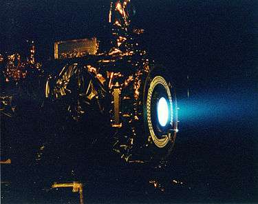
A working ion thruster was built by Harold R. Kaufman in 1959 at the NASA Glenn Research Center facilities. It was similar to a gridded electrostatic ion thruster and used mercury for propellant. Suborbital tests were conducted during the 1960s and in 1964, the engine was sent into a suborbital flight aboard the Space Electric Rocket Test 1 (SERT 1).[7][8] It successfully operated for the planned 31 minutes before falling to Earth.[9] This test was followed by an orbital test, SERT-2, in 1970.[10][11]
An alternate form of electric propulsion, the Hall effect thruster was studied independently in the U.S. and the Soviet Union in the 1950s and 1960s. Hall effect thrusters had operated on Soviet satellites since 1972. Until the 1990s they were mainly used for satellite stabilization in North-South and in East-West directions. Some 100–200 engines completed missions on Soviet and Russian satellites until the late 1990s.[12] Soviet thruster design was introduced to the West in 1992 after a team of electric propulsion specialists, under the support of the Ballistic Missile Defense Organization, visited Soviet laboratories.
General description
Ion thrusters use beams of ions (electrically charged atoms or molecules) to create thrust in accordance with momentum conservation. The method of accelerating the ions varies, but all designs take advantage of the charge/mass ratio of the ions. This ratio means that relatively small potential differences can create high exhaust velocities. This reduces the amount of reaction mass or propellant required, but increases the amount of specific power required compared to chemical rockets. Ion thrusters are therefore able to achieve high specific impulses. The drawback of the low thrust is low acceleration because the mass of the electric power unit directly correlates with the amount of power. This low thrust makes ion thrusters unsuited for launching spacecraft into orbit, but effective for in-space propulsion.
Ion thrusters are categorized as either electrostatic or electromagnetic. The main difference is the method for accelerating the ions.
- Electrostatic ion thrusters use the Coulomb force and accelerate the ions in the direction of the electric field.
- Electromagnetic ion thrusters use the Lorentz force to move the ions.
Power supplies for ion thrusters are usually electric solar panels, but at sufficiently large distances from the sun, nuclear power is used. In each case, the power supply mass is proportional to the peak power that can be supplied, and both provide, for this application, no limit to the energy.
Electric thrusters tend to produce low thrust, which results in low acceleration. Using 1 g is 9.81 m/s2; F = m a ⇒ a = F/m. An NSTAR thruster producing a thrust (force) of 92 mN[13] will accelerate a satellite with a mass of 1 000 kg by 0.092 N / 1 000 kg = 0.000092 m/s2 (or 9.38×10⁻⁶ g).
F = 2*η*P/(g * Isp)
Where
- F is the thrust (force) in N,
- η is the efficiency, a dimensionless value between 0 and 1 (70% efficiency is 0.7),
- P is the electrical power energy going into the thruster in W,
- g is a constant, the acceleration due to gravity 9.81 m/s2,
- Isp is the specific impulse in s.
Electrostatic ion thrusters
Gridded electrostatic ion thrusters
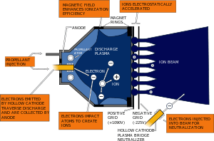
Gridded electrostatic ion thrusters commonly utilize xenon gas. This gas has no charge and is ionized by bombarding it with energetic electrons. These electrons can be provided from a hot cathode filament and when accelerated in the electrical field of the cathode, fall to the anode. Alternatively, the electrons can be accelerated by the oscillating electric field induced by an alternating magnetic field of a coil, which results in a self-sustaining discharge without a cathode (radio frequency ion thruster).
The positively charged ions are extracted by an extraction system consisting of 2 or 3 multi-aperture grids. After entering the grid system by the plasma sheath, the ions are accelerated by the potential difference between the first and second grid (named screen and accelerator grid) to the final ion energy of (typically) 1–2 keV, generating the thrust.
Ion thrusters emit a beam of positive charged xenon ions only. To avoid charging up the spacecraft, another cathode is placed near the engine to emit an electron current into the ion beam with net neutral electrostatic charge.[9] This prevents the beam of ions from being attracted (and returning) to the spacecraft, cancelling the thrust.
Gridded electrostatic ion thruster research (past/present):
- NASA Solar Technology Application Readiness (NSTAR) - 2,3 kW, used on two successful missions
- NASA’s Evolutionary Xenon Thruster (NEXT) - 6,9 kW, flight qualification hardware built
- Nuclear Electric Xenon Ion System (NEXIS)
- High Power Electric Propulsion (HiPEP) - 25 kW, test example built and run briefly on the ground
- EADS Radio-Frequency Ion Thruster (RIT)
- Dual-Stage 4-Grid (DS4G)[14][15]
Hall effect thrusters

Hall effect thrusters accelerate ions by means of an electric potential between a cylindrical anode and a negatively charged plasma that forms the cathode. The bulk of the propellant (typically xenon) is introduced near the anode, where it ionizes and flows toward the cathode; ions accelerate towards and through it, picking up electrons as they leave to neutralize the beam and leave the thruster at high velocity.
The anode is at one end of a cylindrical tube. In the center is a spike that is wound to produce a radial magnetic field between it and the surrounding tube. The ions are largely unaffected by the magnetic field, since they are too massive. However, the electrons produced near the end of the spike to create the cathode are trapped by the magnetic field and held in place by their attraction to the anode. Some of the electrons spiral down towards the anode, circulating around the spike in a Hall current. When they reach the anode they impact the uncharged propellant and cause it to be ionized, before finally reaching the anode and closing the circuit.[16]
Field-emission electric propulsion
Field-emission electric propulsion (FEEP) thrusters use either caesium or indium as the propellant. The design comprises a small propellant reservoir that stores the liquid metal, a narrow tube or a system of parallel plates that the liquid flows through and an accelerator (a ring or an elongated aperture in a metallic plate) about a millimeter past the tube end. Caesium and indium are used due to their high atomic weights, low ionization potentials and low melting points. Once the liquid metal reaches the end of the tube, an electric field applied between the emitter and the accelerator causes the liquid surface to deform into a series of protruding cusps ("Taylor cones"). At a sufficiently high applied voltage, positive ions are extracted from the tips of the cones.[17][18][19] The electric field created by the emitter and the accelerator then accelerates the ions. An external source of electrons neutralizes the positively charged ion stream to prevent charging of the spacecraft.
Electromagnetic thrusters
Pulsed inductive thrusters
Pulsed inductive thrusters (PIT) use pulses instead of continuous thrust and have the ability to run on power levels on the order of megawatts (MW). PITs consist of a large coil encircling a cone shaped tube that emits the propellant gas. Ammonia is the gas commonly used. For each pulse, a large charge builds up in a group of capacitors behind the coil and is then released. This creates a current that moves circularly in the direction of jθ. The current then creates a magnetic field in the outward radial direction (Br), which then creates a current in the gas that has just been released in the opposite direction of the original current. This opposite current ionizes the ammonia. The positively charged ions are accelerated away from the engine due to the electric field jθ crossing the magnetic field Br, due to the Lorentz Force.[20]
Magnetoplasmadynamic / Lithium Lorentz force accelerator
Magnetoplasmadynamic (MPD) thrusters and lithium Lorentz force accelerator (LiLFA) thrusters use roughly the same idea. The LiLFA thruster builds off of the MPD thruster. Hydrogen, argon, ammonia and nitrogen can be used as propellant. In a certain configuration, the ambient gas in Low Earth Orbit (LEO) can be used as a propellant. The gas enters the main chamber where it is ionized into plasma by the electric field between the anode and the cathode. This plasma then conducts electricity between the anode and the cathode, closing the circuit. This new current creates a magnetic field around the cathode, which crosses with the electric field, thereby accelerating the plasma due to the Lorentz force.
The LiLFA thruster uses the same general idea as the MPD thruster, with two main differences. First, the LiLFA uses lithium vapor, which can be stored as a solid. The other difference is that the single cathode is replaced by multiple, smaller cathode rods packed into a hollow cathode tube. MPD cathodes are easily corroded due to constant contact with the plasma. In the LiLFA thruster the lithium vapor is injected into the hollow cathode and is not ionized to its plasma form/corrode the cathode rods until it exits the tube. The plasma is then accelerated using the same Lorentz Force.[21][22][23]
In 2013 Russian company the Chemical Automatics Design Bureau successfully conducted a bench test of their MPD engine for long-distance space travel.[24]
Electrodeless plasma thrusters
Electrodeless plasma thrusters have two unique features: the removal of the anode and cathode electrodes and the ability to throttle the engine. The removal of the electrodes eliminates erosion, which limits lifetime on other ion engines. Neutral gas is first ionized by electromagnetic waves and then transferred to another chamber where it is accelerated by an oscillating electric and magnetic field, also known as the ponderomotive force. This separation of the ionization and acceleration stages allows throttling of propellant flow, which then changes the thrust magnitude and specific impulse values.[25]
Helicon double layer thrusters
A helicon double layer thruster is a type of plasma thruster that ejects high velocity ionized gas to provide thrust. In this design, gas is injected into a tubular chamber (the source tube) with one open end. Radio frequency AC power (at 13,56 MHz in the prototype design) is coupled into a specially shaped antenna wrapped around the chamber. The electromagnetic wave emitted by the antenna causes the gas to break down and form a plasma. The antenna then excites a helicon wave in the plasma, which further heats it. The device has a roughly constant magnetic field in the source tube (supplied by solenoids in the prototype), but the magnetic field diverges and rapidly decreases in magnitude away from the source region and might be thought of as a kind of magnetic nozzle. In operation, a sharp boundary separates the high density plasma inside the source region and the low density plasma in the exhaust, which is associated with a sharp change in electrical potential. Plasma properties change rapidly across this boundary, which is known as a current-free electric double layer. The electrical potential is much higher inside the source region than in the exhaust and this serves both to confine most of the electrons and to accelerate the ions away from the source region. Enough electrons escape the source region to ensure that the plasma in the exhaust is neutral overall.
VASIMR
VASIMR, or Variable Specific Impulse Magnetoplasma Rocket, works by using radio waves to ionize a propellant into a plasma and then a magnetic field to accelerate the plasma out of the back of the rocket engine to generate thrust. The VASIMR is currently being developed by the private company Ad Astra Rocket Company, headquartered in Houston, TX with of help from a NS Canada based company Nautel, producing the 200 kW RF generators for ionizing propellant. Some of the components and "Plasma Shoots" experiments are tested in a laboratory settled in Liberia, Costa Rica. This project is led by former NASA astronaut Dr. Franklin Chang-Díaz (CRC-USA). Recently the Costa Rican Aerospace Alliance announced its cooperation with this project by developing an exterior support device for the VASIMR to be fitted in the exterior of the International Space Station, as part of the plan to test the VASIMR in space, this test phase is now expected to be conducted in 2016. The supposed 200 megawatt engine could reduce the duration of flight from Earth to Jupiter or Saturn from six years to fourteen months, and Mars from 6 months to 39 days.[26]
Microwave electrothermal thrusters
Under a research grant from the NASA Lewis Research Center during the 1980s and 1990s, Martin C. Hawley and Jes Asmussen led a team engineers in developing a Microwave Electrothermal Thruster (MET).[27]
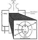
In the discharge chamber, Microwave (MW) energy flows into the center containing a high level of ions (I), causing neutral species in the gaseous propellant to ionize. Excited species flow out (FES) through the low ion region (II) to a neutral region (III) where the ions complete their recombination, replaced with the flow of neutral species (FNS) towards the center. Meanwhile, energy is lost to the chamber walls through heat conduction and convection (HCC), along with Radiation (Rad). The remaining energy absorbed into the gaseous propellant is converted into thrust.
Comparisons
| Engine | Propellant | Required power (kW) |
Specific impulse (s) |
Thrust (mN) |
Thruster mass (kg) |
|---|---|---|---|---|---|
| NSTAR | Xenon | 2.3 | 3,300 to 1,700[28] | 92 max.[13] | |
| NEXT[13] | Xenon | 6.9[29] | 4,190[29][30][31] | 236 max[13][31] | |
| NEXIS[32] | Xenon | 20.5 | |||
| RIT 22[33] | Xenon | 5 | |||
| BHT8000 [34] | Xenon | 8 | 2210 | 449 | 25 |
| Hall effect | Xenon | 75 | |||
| FEEP | Liquid Caesium | 6×10⁻⁵–0.06 | 6,000–10,000[18] | 0.001–1[18] |
| Engine | Propellant | Required power (kW) |
Specific impulse (s) |
Thrust (mN) |
Thruster mass (kg) |
|---|---|---|---|---|---|
| Hall effect | Bismuth | 1,9[35] | 1 520 (anode)[35] | 143 (discharge) [35] | |
| Hall effect | Bismuth | 25 | |||
| Hall effect | Bismuth | 140 | |||
| Hall effect | Iodine | 0,2 [36] | 1 510 (anode)[36] | 12,1 (discharge) [36] | |
| Hall effect | Iodine | 7 [37] | 1 950 [37] | 413 [37] | |
| HiPEP | Xenon | 20–50[38] | 6 000–9 000[38] | 460–670[38] | |
| MPDT | Hydrogen | 1 500 | 4 900 | 26 300 | |
| MPDT | Hydrogen | 3 750 | 3 500 | 88 500 | |
| MPDT | Hydrogen | 7 500 | 6 000 | 60 000 | |
| LiLFA | Lithium Vapor | 500 | 4 077 | 12 000 | |
| FEEP | Liquid Caesium | 6×10⁻⁵–0.06 | 6 000–10 000[18] | 0,001–1[18] | |
| VASIMR | Argon | 200 | 3 000–12 000 | ~5 000[39] | 620[40] |
| CAT[41] | Xenon, Iodine, water[42] | 0,01 | 690[43] | 1,1-2 | <1 (73 mN/kW)[42] |
| DS4G | Xenon | 250 | 19 300 | 2 500 max. | 5 |
| KLIMT | Krypton | 0,5[44] | 4[44] |
Lifetime
Ion thrusters' low thrust requires continuous thrust for a long time to achieve the necessary change in velocity (delta-v) for a particular mission. Ion thrusters are designed to provide continuous operation for intervals of weeks to years.
The lifetime of electrostatic ion thrusters is limited by several processes. In electrostatic gridded designs, charge-exchange ions produced by the beam ions with the neutral gas flow can be accelerated towards the negatively biased accelerator grid and cause grid erosion. End-of-life is reached when either the grid structure fails or the holes in the grid become large enough that ion extraction is substantially affected; e.g., by the occurrence of electron backstreaming. Grid erosion cannot be avoided and is the major lifetime-limiting factor. Thorough grid design and material selection enable lifetimes of 20 000 hours or more.
A test of the NASA Solar Technology Application Readiness (NSTAR) electrostatic ion thruster resulted in 30 472 hours (roughly 3,5 years) of continuous thrust at maximum power. Post-test examination indicated the engine was not approaching failure.[45]
The NASA Evolutionary Xenon Thruster (NEXT) Project operated continuously for more than 48 000 hours.[46] The test was conducted in a high vacuum test chamber. Over the course of the 5 1/2 + year test, the engine consumed approximately 870 kilograms of xenon propellant. The total impulse generated would require over 10,000 kilograms of conventional rocket propellant for a similar application.
Hall thrusters suffer from strong erosion of the ceramic discharge chamber by impact of energetic ions: a test reported in 2010[47] showed erosion of around 1 mm per hundred hours of operation, though this is inconsistent with observed on-orbit lifetimes of a few thousand hours.
NASA's Jet Propulsion Laboratory's ion drives have provided continuous operation of more than 3 years.[1][2]
Propellants
Ionization energy represents a large percentage of the energy needed to run ion drives. The ideal propellant is thus easy to ionize and has a high mass/ionization energy ratio. In addition, the propellant should not erode the thruster to any great degree to permit long life; and should not contaminate the vehicle.[48]
Many current designs use xenon gas, as it is easy to ionize, has a reasonably high atomic number, is inert and causes low erosion. However, xenon is globally in short supply and expensive.
Older designs used mercury, but this is toxic and expensive, tended to contaminate the vehicle with the metal and was difficult to feed accurately.
Other propellants, such as bismuth and iodine, show promise, particularly for gridless designs, such as Hall effect thrusters.[35][36][37]
VASIMR design (and other plasma-based engines) are theoretically able to use practically any material for propellant. However, in current tests the most practical propellant is argon, which is relatively abundant and inexpensive.
The CubeSat Ambipolar Thruster (CAT) used on the Mars Array of Ionospheric Research Satellites Using the CubeSat Ambipolar Thruster (MARS-CAT) mission proposes to use solid Iodine as the propellant to minimize storage volume.[43]
Energy efficiency
Ion thruster efficiency is the kinetic energy of the exhaust jet emitted per second divided by the electrical power into the device.
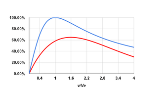
Overall system energy efficiency is determined by the propulsive efficiency, which depends on vehicle speed and exhaust speed. Some thrusters can vary exhaust speed in operation, but all can be designed with different exhaust speeds. At the lower end of Isps the overall efficiency drops, because ionization takes up a larger percentage energy and at the high end propulsive efficiency is reduced.
Optimal efficiencies and exhaust velocities for any given mission can be calculated to give minimum overall cost.
Missions
Ion thrusters have many in-space propulsion applications. The best applications make use of the long mission interval when significant thrust is not needed. Examples of this include orbit transfers, attitude adjustments, drag compensation for low Earth orbits, fine adjustments for scientific missions and cargo transport between propellant depots, e.g., for chemical fuels. Ion thrusters can also be used for interplanetary and deep-space missions where acceleration rates are not crucial. Continuous thrust over a long interval can reach high velocities while consuming far less fuel than traditional chemical rockets.
Among electric thrusters, ion thrusters have received the most serious commercial and academic consideration. Ion thrusters are seen as the best solution for these missions, as they require high change in velocity but do not require rapid acceleration.
Demonstration vehicles
SERT
Ion propulsion systems were first demonstrated in space by the NASA Lewis (now Glenn Research Center) missions "Space Electric Rocket Test" (SERT) I and II.[49] SERT-1 was launched July 20, 1964, and successfully proved that the technology operated as predicted in space. These were electrostatic ion thrusters using mercury and cesium as the reaction mass. SERT-II, launched on February 3, 1970,[50][51] verified the operation of two mercury ion engines for thousands of running hours.[52]
Operational missions
Ion thrusters are routinely used for station-keeping on commercial and military communication satellites in geosynchronous orbit. The Soviet Union pioneered this field, using Stationary Plasma Thruster (SPT) thrusters on satellites starting in the early 1970s.
Two geostationary satellites (ESA's Artemis in 2001–03[53] and the US military's AEHF-1 in 2010–12[54]) used the ion thruster to change orbit after the chemical-propellant engine failed. Boeing[55] began using ion thrusters for station-keeping in 1997 and planned in 2013–14 to offer a variant on their 702 platform, with no chemical engine and ion thrusters for orbit raising; this permits a significantly lower launch mass for a given satellite capability. AEHF-2 used a chemical engine to raise perigee to 10,150 miles and proceeded to geosynchronous orbit using electric propulsion.[56]
In Earth orbit
GOCE
ESA's Gravity Field and Steady-State Ocean Circulation Explorer was launched on March 16, 2009. It used ion propulsion throughout its twenty-month mission to combat the air-drag it experienced in its low orbit before intentionally deorbiting on November 11, 2013.
In deep space
Deep Space 1
NASA developed the NSTAR ion engine for use in interplanetary science missions beginning in the late-1990s. It was space-tested in the highly successful space probe Deep Space 1, launched in 1998. This was the first use of electric propulsion as the interplanetary propulsion system on a science mission.[49] Based on the NASA design criteria, Hughes Research Labs, developed the Xenon Ion Propulsion System (XIPS) for performing station keeping on geosynchronous satellites.. Hughes (EDD) manufactured the NSTAR thruster used on the spacecraft.
Hayabusa
The Japanese space agency's Hayabusa launched in 2003 and successfully rendezvoused with the asteroid 25143 Itokawa and remained in close proximity for months to collect samples and information. It was powered by four xenon ion engines. Its xenon ions were generated by microwave electron cyclotron resonance and an erosion-resistant carbon/carbon-composite material for its acceleration grid.[57] Although the ion engines on Hayabusa had technical difficulties, in-flight reconfiguration allowed one of the four engines to be repaired and allowed the mission to successfully return to Earth.[58]
Smart 1
The European Space Agency's satellite SMART-1 launched in 2003 using a Snecma PPS-1350-G Hall thruster to get from GTO to lunar orbit. This satellite completed its mission on September 3, 2006, in a controlled collision on the Moon's surface, after a trajectory deviation so scientists could see the 3 meter crater the impact created on the visible side of the moon.
Dawn
Dawn launched on September 27, 2007, to explore the asteroid Vesta and the dwarf planet Ceres. It used three Deep Space 1 heritage xenon ion thrusters (firing one at a time). An extended mission to explore other asteroids is possible. Dawn's ion drive is capable of accelerating from 0 to 60 mph (97 km/h) in 4 days of continuous firing.[59]
Planned missions
Several missions are planned to use ion thrusters:
BepiColombo
ESA plans to launch the BepiColombo mission to Mercury in 2017. It uses ion thrusters in combination with swing-bys to get to Mercury, where a chemical rocket will complete orbit insertion.
LISA Pathfinder
LISA Pathfinder is an ESA spacecraft launched in 2015. It does not use ion thrusters as its primary propulsion system, but uses both colloid thrusters and FEEP for precise attitude control — the low thrusts of these propulsion devices make it possible to move the spacecraft incremental distances accurately. It is a test for the possible LISA mission.
International Space Station
As of March 2011, a future launch of an Ad Astra VF-200 200 kW VASIMR electromagnetic thruster was under consideration for testing on the International Space Station.[60][61] The VF-200 is a flight version of the VX-200.[62][63] Since the available power from the ISS is less than 200 kW, the ISS VASIMR would include a trickle-charged battery system allowing for 15 min pulses of thrust. Testing the engine on ISS is valuable, because it orbits at a relatively low altitude and experiences fairly high levels of atmospheric drag, requiring periodic altitude boosts . Altitude reboosting by chemical rockets fulfills this requirement. If the tests of VASIMR reboosting goes according to plan, the increase in specific impulse could mean that the fuel cost will be one-twentieth of the current $210 million annual cost.[60] Hydrogen is generated by the ISS as a by-product and is vented into space.
NASA high-power SEP system demonstration mission
In February 2012 NASA awarded a contract to Northrop Grumman for a test mission (probably using the NEXT engine) capable of extension to 300 kW electrical power.[64]
Mars Array of Ionospheric Research Satellites Using the CubeSat Ambipolar Thruster
The MARS-CAT mission is a two 6U CubeSat mission to study Mars' ionosphere. The mission will investigate its plasma and magnetic structure, including transient plasma structures, magnetic field structure, magnetic activity and correlation with solar wind drivers. The Mars transit proposed is piggyback with Mars2020 using a CubeSat Ambipolar Thruster (CAT) burn for Mars orbit insertion and station keeping.[43]
Interstellar probe
Geoffrey A. Landis proposed to use a space laser source and ion thruster to propel an interstellar probe.[65][66]
Popular culture
The idea of an ion engine first appeared in Donald W Horner's By Aeroplane to the Sun: Being the Adventures of a Daring Aviator and his Friends (1910).[67]
Star Wars films and literature refer to twin ion engines (TIE) starfighters. Also nearly all other star wars crafts are propepelled by ion motors according to sources such as wookieepedia,[68] but the technology is highly different from real ion motors.
See also
- Colloid thruster
- Comparison of orbital rocket engines
- Electrically powered spacecraft propulsion
- Electrostatic fluid accelerator
- List of spacecraft with electric propulsion
- Nano-particle field extraction thruster
- Nuclear electric rocket
- Nuclear pulse propulsion
- Plasma actuator
- Plasma propulsion engine
- Spacecraft propulsion
References
Footnotes
- 1 2 3 4 5 Choueiri, Edgar Y. (2009). New dawn of electric rocket. The Ion Drive
- 1 2 3 4 5 6 7 8 Choueiri, Edgar Y (2009). "New dawn of electric rocket". Scientific American. 300: 58–65. doi:10.1038/scientificamerican0209-58. (subscription required (help)).
- ↑ Electric Spacecraft Propulsion, Electric versus Chemical Propulsion, ESA Science & Technology
- 1 2 Choueiri, E. Y. "A Critical History of Electric Propulsion: The First 50 Years (1906–1956)". Retrieved 2016-10-18.
- ↑ Mark Wright, April 6, 1999, science.nasa.gov, Ion Propulsion 50 years in the making
- ↑ "Robert H. Goddard: American Rocket Pioneer". Smithsonian Scrapbook. Smithsonian Institution Archives. Retrieved March 28, 2012.
- ↑ "Contributions to Deep Space 1". NASA.
- ↑ Ronald J. Cybulski, Daniel M. Shellhammer, Robert R. LoveII, Edward J. Domino, and Joseph T. Kotnik, RESULTS FROM SERT I ION ROCKET FLIGHT TEST, NASA Technical Note D2718 (1965).
- 1 2 "Innovative Engines - Glenn Ion Propulsion Research Tames the Challenges of 21st Century Space Travel". Retrieved 2007-11-19.
- ↑ NASA Glenn, "SPACE ELECTRIC ROCKET TEST II (SERT II) (Accessed July 1, 2010)
- ↑ SERT page at Astronautix (Accessed July 1, 2010)
- ↑ "Native Electric Propulsion Engines Today" (in Russian). Novosti Kosmonavtiki. 1999. Archived from the original on 6 June 2011.
- 1 2 3 4 Shiga, David (2007-09-28). "Next-generation ion engine sets new thrust record". NewScientist. Retrieved 2011-02-02.
- ↑ "ESA and ANU make space propulsion breakthrough" (Press release). ESA. 2006-01-11. Retrieved 2007-06-29.
- ↑ ANU Space Plasma, Power & Propulsion Group (SP3) (2006-12-06). "ANU and ESA make space propulsion breakthrough". DS4G Web Story. The Australian National University. Archived from the original on 2007-06-27. Retrieved 2007-06-30.
- ↑ Oleson, S. R.; Sankovic, J. M. "Advanced Hall Electric Propulsion for Future In-Space Transportation" (PDF). Retrieved 2007-11-21.
- ↑ "FEEP - Field-Emission Electric Propulsion". Retrieved 2012-04-27.
- 1 2 3 4 5 Marcuccio, S.; et al. "Experimental Performance of Field Emission Microthrusters" (PDF). Retrieved 2012-04-27.
- ↑ Marrese-Reading, Colleen; Polk, Jay; Mueller, Juergen; Owens, Al. "In-FEEP Thruster Ion Beam Neutralization with Thermionic and Field Emission Cathodes" (PDF). Retrieved 2007-11-21.
liquid state and wicked up the needle shank to the tip where high electric fields deform the liquid and extract ions and accelerate them up to 130 km/s through 10 kV.
- ↑ Mikellides, Pavlos G. "Pulsed Inductive Thruster (PIT): Modeling and Validation Using the MACH2 Code" (PDF). Retrieved 2007-11-21.
- ↑ Sankaran, K.; Cassady, L.; Kodys, A.D.; Choueiri, E.Y. "A Survey of Propulsion Options for Cargo and Piloted Missions to Mars". Retrieved 2016-10-18.
- ↑ LaPointe, Michael R.; Mikellides, Pavlos G. "High Power MPD Thruster Development at the NASA Glenn Research Center" (PDF). Archived from the original (PDF) on October 11, 2006. Retrieved 2007-11-21.
- ↑ Conley, Buford Ray (May 22, 1999). "Utilization of Ambient Gas as a Propellant for Low Earth Orbit Electric Propulsion" (PDF). Archived from the original (PDF) on June 29, 2011.
- ↑ ""В Воронеже создали двигатель для Марса" в блоге "Перспективные разработки, НИОКРы, изобретения" - Сделано у нас". Сделано у нас.
- ↑ Emsellem, Gregory D. "Development of a High Power Electrodeless Thruster" (PDF). Retrieved 2007-11-21.
- ↑ Zyga, Lisa (2009). Plasma Rocket Could Travel to Mars in 39 Days, http://phys.org/news174031552.html Physorg
- ↑ "Less Fuel, More Thrust: New Engines are Being Designed for Deep Space". The Arugus-Press. 128 (48). Owosso, Michigan. 26 February 1982. p. 10.
- ↑ "Ion Propulsion".
- 1 2 Szondy, David. "NASA's NEXT ion thruster runs five and a half years nonstop to set new record". Retrieved June 26, 2013.
- ↑ Schmidt, George R.; Patterson, Michael J.; Benson, Scott W. "The NASA Evolutionary Xenon Thruster (NEXT): the next step for US deep space propulsion" (PDF).
- 1 2 Herman, Daniel A. (May 3–7, 2010), "NASA's Evolutionary Xenon Thruster (NEXT) Project Qualifi cation Propellant Throughput Milestone: Performance, Erosion, and Thruster Service Life Prediction After 450 kg" (PDF), 57th Joint Army-Navy-NASA-Air Force (JANNAF) Propulsion Meeting, Colorado Springs, Colorado, USA: NASA - Glenn Research Center, retrieved 2014-03-08
- ↑ An overview of the Nuclear Electric Xenon Ion System (NEXIS) program (2006), 2006-02-10 (Polk, Jay E., Goebel, Don, Brophy, John R., Beatty, John, Monheiser, J., Giles, D.), Scientific Commons
- ↑ Astrium Radiofrequency Ion Thruster, Model RIT-22., EADS Astrium Archived June 13, 2009, at the Wayback Machine.
- ↑ BHT-8000 Busek Hall Effect Thruster
- 1 2 3 4 Szabo, J., Robin, M., Paintal, Pote, B., S., Hruby, V., "High Density Hall Thruster Propellant Investigations," 48th AIAA/ASME/SAE/ASEE Joint Propulsion Conference and Exhibit, AIAA Paper 2012-3853, July 2012.
- 1 2 3 4 Szabo, J., Pote, B., Paintal, S., Robin, M., Hillier, A., Branam, R., Huffman, R. "Performance Evaluation of an Iodine Vapor Hall Thruster". Journal of Propulsion and Power, 28, 4, 2012.
- 1 2 3 4 Szabo, J., Robin, M., Paintal, S., Pote, B., Hruby, V., Freeman, C.,. "Iodine Plasma Propulsion Test Results at 1-10 kW". IEEE Transactions on Plasma Science, Special Issue – Plasma Propulsion, Vol. 43, No. 1, 2015.
- 1 2 3 "HIGH POWER ELECTRIC PROPULSION PROGRAM (HiPEP)". NASA. 2008-12-22.
- ↑ VASIMR VX-200 Performance and Near-term SEP Capability for Unmanned Mars Flight, Tim Glover, Future in Space Operations (FISO) Colloquium, 2011-01-19, accessed 2011-01-31.
- ↑ VASIMR® Spaceflight Engine System Mass Study and Scaling with Power IEPC-2013-149
- ↑ Mike Wall (July 8, 2013). "New Space Engine Could Turn Tiny CubeSats into Interplanetary Explorers". Space.com. Purch. Retrieved June 25, 2015.
- 1 2 "PEPL Thrusters: CubeSat Ambipolar Thruster". pepl.engin.umich.edu. University of Michigan. Retrieved June 25, 2015.
- 1 2 3 "MARS-CAT Mission Implementation". www.marscat.space. University of Houston College of Natural Sciences and Mathematics. Retrieved June 25, 2015.
- 1 2 Krypton Hall effect thruster for space propulsion, IFPiLM, accessed 2014-01-29.
- ↑ "Destructive Physical Analysis of Hollow Cathodes from the Deep Space 1 Flight Spare Ion Engine 30,000 Hr Life Test" (PDF). Retrieved 2007-11-21.
- ↑ "NASA Thruster Achieves World-Record 5+ Years of Operation". Retrieved 2012-06-27.
- ↑ "A closer look at a stationary plasma thruster" (PDF).
- ↑ Rocket Propulsion Elements — Sutton & Biblarz 7th edition
- 1 2 Sovey, J. S.; Rawlin, V. K.; Patterson, M. J. (May–June 2001). "Ion Propulsion Development Projects in U. S.: Space Electric Rocket Test 1 to Deep Space 1". Journal of Propulsion and Power. 17 (3): 517–526. doi:10.2514/2.5806.
- ↑ SPACE ELECTRIC ROCKET TEST II (SERT II), NASA Glenn Research Center. Accessed July 1, 2010.
- ↑ SERT page at Astronautix (Accessed July 1, 2010)
- ↑ Space Electric Rocket Test at NASA.gov
- ↑ ESA. "Artemis team receives award for space rescue". Retrieved 2006-11-16.
- ↑ "Rescue in Space".
- ↑ Spaceflight Now. "Electric propulsion could launch new commercial trend".
- ↑ "AEHF 2 communications satellite keeps on climbing".
- ↑ ISAS. "小惑星探査機はやぶさ搭載イオンエンジン (Ion Engines used on Asteroid Probe Hayabusa)" (in Japanese). Retrieved 2006-10-13.
- ↑ Tabuchi, Hiroko (1 July 2010). "Faulty Space Probe Seen as Test of Japan's Expertise". The New York Times.
- ↑ The Prius of Space, September 13, 2007, NASA Jet Propulsion Laboratory
- 1 2 "Executive summary" (PDF). Ad Astra Rocket Company. January 24, 2010. Retrieved 2010-02-27.
- ↑ Klotz, Irene (7 August 2008). "Plasma Rocket May Be Tested at Space Station". Discovery News. Retrieved 2010-02-27.
- ↑ Whittington, Mark (March 10, 2011). "NASA to Test VF-200 VASIMR Plasma Rocket at the ISS". Yahoo. Retrieved 2012-01-27.
- ↑ Mick, Jason (August 11, 2008). "Commercially Developed Plasma Engine Soon to be Tested in Space". DailyTech. Retrieved 2010-02-27.
- ↑ "NASA Awards Solar Electric Propulsion Flight System Contract".
- ↑ "- Google Scholar".
- ↑ Geoffrey A. Landis. Laser-powered Interstellar Probe on the Geoffrey A. Landis: Science. papers available on the web
- ↑ "Themes : Ion Drive : SFE : Science Fiction Encyclopedia".
- ↑ "Ion drive, Wookiepedia".
Bibliography
- Lerner, Eric J. (October 2000). "Plasma Propulsion in Space" (PDF). The Industrial Physicist. 6 (5): 16–19. Retrieved 2007-06-29.
- ElectroHydroDynamic Thrusters (EHDT), RMCybernetics.
External links
| Wikimedia Commons has media related to Ion propulsion. |
- NASA Jet Propulsion Laboratory
- Colorado State University Electric Propulsion & Plasma Engineering (CEPPE) Laboratory
- Geoffrey A. Landis: Laser-powered Interstellar Probe
- Choueiri, Edgar Y. (2009). New dawn of electric rocket. The Ion Drive
- The revolutionary ion engine that took spacecraft to Ceres
Articles
- "NASA Trumps Star Trek: Ion Drive Live!", The Daily Galaxy April 13, 2009.
- "The Ultimate Space Gadget: NASA's Ion Drive Live!", The Daily Galaxy, July 7, 2009.
- An early experimental Ion engine is on display at the Aerospace Discovery at the Florida Air Museum.
| Chemical rockets |
| ||||||||||||||
|---|---|---|---|---|---|---|---|---|---|---|---|---|---|---|---|
| Electrical thrusters |
| ||||||||||||||
| Nuclear propulsion |
| ||||||||||||||
| Other | |||||||||||||||