Inchworm motor
The inchworm motor is a device that uses piezoelectric actuators to move a shaft with nanometer precision.
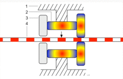
In its simplest form, the inchworm motor uses three piezo-actuators (2 and 3, see Figure 1.) mounted inside a tube (1) and electrified in sequence to grip a shaft (4) which is then moved in a linear direction. Motion of the shaft is due to the extension of the lateral piezo (2) pushing on two clutching piezos (3).
Operation
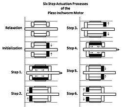
The actuation process of the inchworm motor is a six step cyclical process after the initial relaxation and initialization phase. Initially, all three piezos are relaxed and unextended. To initialize the inchworm motor the clutching piezo closest to the direction of desired motion (which then becomes the forward clutch piezo) is electrified first then the six step cycle begins as follows (see Figure 2.):
Step 1. Extension of the lateral piezo.
Step 2. Extension of the aft clutch piezo.
Step 3. Relaxation of the forward clutch piezo.
Step 4. Relaxation of the lateral piezo.
Step 5. Extension of the forward clutch piezo.
Step 6. Relaxation of the aft clutch piezo.
Electrification of the piezo actuators is accomplished by applying a high bias voltage to the actuators in step according to the "Six Step" process described above. To move long distances the sequence of six steps is repeated many times in rapid succession. Once the motor has moved sufficiently close to the desired final position, the motor may be switched to an optional fine positioning mode. In this mode, the clutches receive constant voltage (one high and the other low), and the lateral piezo voltage is then adjusted to an intermediate value, under continuous feedback control, to obtain the desired final position.
Uses
Scanning Tunneling Microscopy
The inchworm motor is commonly used in scanning tunneling microscopes (STM's). An STM requires nanometer scale control of its scanning tip near the material it is observing. This control can be accomplished by connecting the scanning tip to the shaft of the inchworm motor. The inchworm motor, in turn, allows control in a direction normal to the plane of the observed material's surface. Movement across the surface is commonly referred to as movement in the x-y plane, whereas movement normal to the surface is commonly referred to as movement in the z-direction. Movement of the scanning tip by the inchworm motor is either manually controlled or automatically controlled by connecting the motor to a feedback system.
Patch Clamping
The inchworm motor can be used in the patch clamping of biological cells. This technique is most often performed with an optical microscope and micromanipulator holding a glass pipette. The inchworm motor is particularly ideal in patch clamping because it provides the operator with virtually an instantaneous, precise, smooth and predictable motion without drift.