Ground-penetrating radar
Ground-penetrating radar (GPR) is a geophysical method that uses radar pulses to image the subsurface. This nondestructive method uses electromagnetic radiation in the microwave band (UHF/VHF frequencies) of the radio spectrum, and detects the reflected signals from subsurface structures. GPR can have applications in a variety of media, including rock, soil, ice, fresh water, pavements and structures. In the right conditions, practitioners can use GPR to detect subsurface objects, changes in material properties, and voids and cracks.[1]
GPR uses high-frequency (usually polarized) radio waves, usually in the range 10 MHz to 2.6 GHz. A GPR transmitter emits electromagnetic energy into the ground. When the energy encounters a buried object or a boundary between materials having different permittivities, it may be reflected or refracted or scattered back to the surface. A receiving antenna can then record the variations in the return signal. The principles involved are similar to seismology, except GPR methods implement electromagnetic energy rather than acoustic energy, and energy may be reflected at boundaries where subsurface electrical properties change rather than subsurface mechanical properties as is the case with seismic energy.
The electrical conductivity of the ground, the transmitted center frequency, and the radiated power all may limit the effective depth range of GPR investigation. Increases in electrical conductivity attenuate the introduced electromagnetic wave, and thus the penetration depth decreases. Because of frequency-dependent attenuation mechanisms, higher frequencies do not penetrate as far as lower frequencies. However, higher frequencies may provide improved resolution. Thus operating frequency is always a trade-off between resolution and penetration. Optimal depth of subsurface penetration is achieved in ice where the depth of penetration can achieve several thousand metres (to bedrock in Greenland) at low GPR frequencies. Dry sandy soils or massive dry materials such as granite, limestone, and concrete tend to be resistive rather than conductive, and the depth of penetration could be up to 15-metre (49 ft). In moist and/or clay-laden soils and materials with high electrical conductivity, penetration may be as little as a few centimetres.
Ground-penetrating radar antennas are generally in contact with the ground for the strongest signal strength; however, GPR air-launched antennas can be used above the ground.
Cross borehole GPR has developed within the field of hydrogeophysics to be a valuable means of assessing the presence and amount of soil water.
History
The first patent for a system designed to use continuous-wave radar to locate buried objects was submitted by Gotthelf Leimbach and Heinrich Löwy in 1910, six years after the first patent for radar itself (patent DE 237 944). A patent for a system using radar pulses rather than a continuous wave was filed in 1926 by Dr. Hülsenbeck (DE 489 434), leading to improved depth resolution. A glacier's depth was measured using ground penetrating radar in 1929 by W. Stern.[2]
Further developments in the field remained sparse until the 1970s, when military applications began driving research. Commercial applications followed and the first affordable consumer equipment was sold in 1985.[2]
Applications


GPR has many applications in a number of fields. In the Earth sciences it is used to study bedrock, soils, groundwater, and ice. It is of some utility in prospecting for gold nuggets and for diamonds in alluvial gravel beds, by finding natural traps in buried stream beds that have the potential for accumulating heavier particles.[3] The Chinese lunar rover Yutu has a GPR on its underside to investigate the soil and crust of the Moon.
Engineering applications include nondestructive testing (NDT) of structures and pavements, locating buried structures and utility lines, and studying soils and bedrock. In environmental remediation, GPR is used to define landfills, contaminant plumes, and other remediation sites, while in archaeology it is used for mapping archaeological features and cemeteries. GPR is used in law enforcement for locating clandestine graves and buried evidence. Military uses include detection of mines, unexploded ordnance, and tunnels.
Borehole radars utilizing GPR are used to map the structures from a borehole in underground mining applications. Modern directional borehole radar systems are able to produce three-dimensional images from measurements in a single borehole.[4]
One of the other main applications for ground-penetrating radars is for locating underground utilities. Standard electromagnetic induction utility locating tools require utilities to be conductive. These tools are ineffective for locating plastic conduits or concrete storm and sanitary sewers. Since GPR detects variations in dielectric properties in the subsurface, it can be highly effective for locating non-conductive utilities.
GPR is often used on the Channel 4 television programme Time Team which uses the technology to determine a suitable area for examination by means of excavations. In 1992 GPR was used to recover £150,000 in cash that kidnapper Michael Sams received as a ransom for an estate agent he had kidnapped after Sams buried the money in a field.[5]
Archaeology
Ground penetrating radar survey is one method used in archaeological geophysics. GPR can be used to detect and map subsurface archaeological artifacts, features, and patterning.[6]

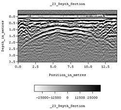
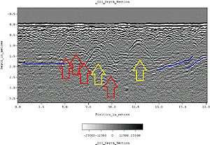
The concept of radar is familiar to most people. With ground penetrating radar, the radar signal – an electromagnetic pulse – is directed into the ground. Subsurface objects and stratigraphy (layering) will cause reflections that are picked up by a receiver. The travel time of the reflected signal indicates the depth. Data may be plotted as profiles, as planview maps isolating specific depths, or as three-dimensional models.
GPR can be a powerful tool in favorable conditions (uniform sandy soils are ideal). Like other geophysical methods used in archaeology (and unlike excavation) it can locate artifacts and map features without any risk of damaging them. Among methods used in archaeological geophysics it is unique both in its ability to detect some small objects at relatively great depths, and in its ability to distinguish the depth of anomaly sources.
The principal disadvantage of GPR is that it is severely limited by less-than-ideal environmental conditions. Fine-grained sediments (clays and silts) are often problematic because their high electrical conductivity causes loss of signal strength; rocky or heterogeneous sediments scatter the GPR signal, weakening the useful signal while increasing extraneous noise.
In the field of cultural heritage GPR with high frequency antenna is also used for investigating historical masonry structures, detecting cracks and decay patterns of columns and detachment of frescoes.[7]
Military
Military applications of ground-penetrating radar include detection of unexploded ordnance and detecting tunnels. In military applications and other common GPR applications, practitioners often use GPR in conjunction with other available geophysical techniques such as electrical resistivity and electromagnetic induction methods.
Vehicle Localization
A recent novel approach to vehicle localization using prior map based images from ground penetrating radar has been demonstrated. Termed "Localizing Ground Penetrating Radar" (LGPR), centimeter level accuracies at speeds up to 60 mph have been demonstrated.[8]
Three-dimensional imaging
Individual lines of GPR data represent a sectional (profile) view of the subsurface. Multiple lines of data systematically collected over an area may be used to construct three-dimensional or tomographic images. Data may be presented as three-dimensional blocks, or as horizontal or vertical slices. Horizontal slices (known as "depth slices" or "time slices") are essentially planview maps isolating specific depths. Time-slicing has become standard practice in archaeological applications, because horizontal patterning is often the most important indicator of cultural activities.[9]
Limitations
The most significant performance limitation of GPR is in high-conductivity materials such as clay soils and soils that are salt contaminated. Performance is also limited by signal scattering in heterogeneous conditions (e.g. rocky soils).
Other disadvantages of currently available GPR systems include:
- Interpretation of radargrams is generally non-intuitive to the novice.
- Considerable expertise is necessary to effectively design, conduct, and interpret GPR surveys.
- Relatively high energy consumption can be problematic for extensive field surveys.
radar is sensitive to changes in material composition, detecting changes requires movement. When looking through stationary items using surface-penetrating or ground-penetrating radar, the equipment needs to be moved in order for the radar to examine the specified area by looking for differences in material composition. While it can identify items such as pipes, voids, and soil, it cannot identify the specific materials, such as gold and precious gems. It can however, be useful in providing subsurface mapping of potential gem-bearing pockets, or "vugs." The readings can be confused by moisture in the ground, and they can't separate gem-bearing pockets from the non-gem-bearing ones.[10]
| Antenna | Approximate Penetration in Dense Wet Clay | Approximate Penetration in Clean Dry Sand | Example of Smallest Visible Object |
|---|---|---|---|
| 100 MHz | 20 ft (6m) | 60 ft+ (18m+) | Tunnel @ 60 ft (18m) depth
2 ft (60 cm) Pipe @ 20 ft (6m) depth |
| 250 MHz | 13 ft (4m) | 40 ft (12m) |
3 ft. (90 cm) Pipe @ 12m 6in. (15 cm) Pipe @ 13 ft (4m) |
| 500 MHz | 6 ft (1.8m) | 14.5 ft. (4.4m) | 4in. (10 cm) pipe @ 4m
3/16 in. (0.5 cm) hose 1.8m and less |
| 1000 MHz | 3 ft (90 cm) | 6 ft (1.8m) | 3/16 in. (0.5 cm) hose @ 3 ft. (90 cm)
Wire mesh, shallow |
| 2000 MHz | .5 ft (15 cm) | 2 ft. (60 cm) | Monofilament fishing line |

When determining depth capabilities, the frequency range of the antenna dictates the size of the antenna and the depth capability. The grid spacing which is scanned is based on the size of the targets that need to be identified and the results required. Typical grid spacings can be 1 meter, 3 ft, 5 ft, 10 ft, 20 ft for ground surveys and 1in.-1 ft. for walls and floors.
The speed at which a radar signal travels is dependent upon the composition of the material being penetrated. The depth to a target is determined based on the amount of time it takes for the radar signal to reflect back to the unit’s antenna. Radar signals travel at different velocities through different types of materials. It is possible to use the depth to a known object to determine a specific velocity and then calibrate the depth calculations.
Power regulation
In 2005, the European Telecommunications Standards Institute introduced legislation to regulate GPR equipment and GPR operators to control excess emissions of electromagnetic radiation.[11] The European GPR association (EuroGPR) was formed as a trade association to represent and protect the legitimate use of GPR in Europe.
Similar technologies
Ground-penetrating radar uses a variety of technologies to generate the radar signal: these are impulse,[12] stepped frequency, frequency-modulated continuous-wave (FMCW), and noise. Systems on the market in 2009 also use Digital signal processing (DSP) to process the data during survey work rather than off-line.
A special kind of GPR uses unmodulated continuous-wave signals. This holographic subsurface radar differs from other GPR types in that it records plan-view subsurface holograms. Depth penetration of this kind of radar is rather small (20–30 cm), but lateral resolution is enough to discriminate different types of landmines in the soil, or cavities, defects, bugging devices, or other hidden objects in walls, floors, and structural elements.[13][14]
GPR is used on vehicles for close-in high-speed road survey and landmine detection as well as in stand-off mode.
Pipe-Penetrating Radar (PPR) is an application of GPR technologies applied in-pipe where the signals are directed through pipe and conduit walls to detect pipe wall thickness and voids behind the pipe walls.
Wall-penetrating radar can read through walls and even act as a motion sensor for police.
The "Mineseeker Project" seeks to design a system to determine whether landmines are present in areas using ultra wideband synthetic aperture radar units mounted on blimps.
References
- ↑ Daniels DJ (ed.) (2004). Ground Penetrating Radar (2nd ed.). Knoval (Institution of Engineering and Technology). pp. 1–4. ISBN 978-0-86341-360-5.
- 1 2 "History of Ground Penetrating Radar Technology". Ingenieurbüro obonic. Retrieved 13 February 2016.
- ↑ Wilson, M. G. C.; Henry, G.; Marshall, T. R. (2006). "A review of the alluvial diamond industry and the gravels of the North West Province, South Africa" (PDF). South African Journal of Geology. Geological Society of South Africa. 109 (3): 301–314. doi:10.2113/gssajg.109.3.301. Retrieved 9 December 2012.
- ↑ Hofinghoff, Jan-Florian (2013). "Resistive Loaded Antenna for Ground Penetrating Radar Inside a Bottom Hole Assembly". IEEE Transactions on Antennas and Propagation. IEEE. 61 (12). doi:10.1109/TAP.2013.2283604.
- ↑ Birmingham Mail
- ↑ Lowe, Kelsey M; Wallis, Lynley A.; Pardoe, Colin; Marwick, Benjamin; Clarkson, Christopher J; Manne, Tiina; Smith, M A; Fullagar, Richard 2014. Ground-penetrating radar and burial practices in western Arnhem Land, Australia. Archaeology in Oceania 49 (3): 148–157 doi:10.1002/arco.5039
- ↑ N Masini, R Persico, E Rizzo. Some examples of GPR prospecting for monitoring of the monumental heritage. Journal of Geophysics and Engineering 7 (2), 190, doi:10.1088/1742-2132/7/2/S05
- ↑ Cornick, Matthew; Koechling, Jeffrey; Stanley, Byron; Zhang, Beijia (2016-01-01). "Localizing Ground Penetrating RADAR: A Step Toward Robust Autonomous Ground Vehicle Localization". Journal of Field Robotics. 33 (1): 82–102. doi:10.1002/rob.21605. ISSN 1556-4967.
- ↑ Conyers, Lawrence B. And Dean Goodman 1997 Ground Penetrating Radar: An Introduction for Archaeologists. Walnut Creek, CA.: Altamira Press
- ↑ "Gems and Technology - Vision Underground". The Ganoksin Project. Retrieved 5 February 2014.
- ↑ ETSI EG 202 730 V1.1.1 (2009–09), "Electromagnetic compatibility and Radio spectrum Matters (ERM); Code of Practice in respect of the control, use and application of Ground Probing Radar (GPR) and Wall Probing Radar (WPR) systems and equipment
- ↑ An impulse generator for the ground penetrating radar
- ↑ Zhuravlev, A.V.; Ivashov, S.I.; Razevig, V.V.; Vasiliev, I.A.; Türk, A.S.; Kizilay, A. (2013). "Holographic subsurface imaging radar for applications in civil engineering". (PDF). IET International Radar Conference. Xi'an, China: IET. doi:10.1049/cp.2013.0111 http://www.rslab.ru/downloads/A0065.pdf. Missing or empty
|title=(help) - ↑ Ivashov, S. I.; Razevig, V. V.; Vasiliev, I. A.; Zhuravlev, A. V.; Bechtel, T. D.; Capineri, L. (2011). "Holographic Subsurface Radar of RASCAN Type: Development and Application" (PDF). IEEE Journal of Selected Topics in Applied Earth Observation and Remote Sensing. 4 (4): 763–778. doi:10.1109/JSTARS.2011.2161755. Retrieved 26 September 2013.
- Borchert, Olaf: Receiver Design for a Directional Borehole Radar System Dissertation, University of Wuppertal, 2008,
Further reading
An overview of scientific and engineering applications can be found in:
- Jol, H. M.. (Ed.) (2008). Ground Penetrating Radar Theory and Applications. Elsevier.
A general overview of geophysical methods in archaeology can be found in the following works:
- Clark, Anthony J. (1996). Seeing Beneath the Soil. Prospecting Methods in Archaeology. London, United Kingdom: B.T. Batsford Ltd.
- Conyers, L. B. (2004). Ground-penetrating Radar for Archaeology. Walnut Creek, CA., United States: AltaMira Press Ltd.
- Gaffney, Chris; John Gater (2003). Revealing the Buried Past: Geophysics for Archaeologists. Stroud, United Kingdom: Tempus.
External links
| Wikimedia Commons has media related to Ground penetrating radars. |
- EUROGPR – The European GPR regulatory body
- GprMax – GPR numerical simulator based on the FDTD method
- Short movie showing acquisition, processing and accuracy of GPR readings
- Ground Penetrating Radar Fundamentals
- FDTD Animation of sample GPR propagation on Youtube
- GPR Electromagnetic Emissions Safety Information