Global Positioning System
| Country of origin | United States |
|---|---|
| Operator(s) | AFSPC |
| Type | Military, civilian |
| Status | Operational |
| Coverage | Global |
| Precision | 5 meters |
| Constellation size | |
| Total satellites | 32 |
| Satellites in orbit | 31 |
| First launch | February 1978 |
| Total launches | 72 |
| Orbital characteristics | |
| Regime(s) | 6x MEO planes |
| Orbital height | 20,180 km (12,540 mi) |
| Geodesy | ||||||||||||||||
|---|---|---|---|---|---|---|---|---|---|---|---|---|---|---|---|---|
 | ||||||||||||||||
| Fundamentals | ||||||||||||||||
| Concepts | ||||||||||||||||
| Technologies | ||||||||||||||||
| Standards | ||||||||||||||||
|
||||||||||||||||
| History | ||||||||||||||||


The Global Positioning System (GPS), also known as Navstar GPS[1][2][3] or simply Navstar,[4] is a global navigation satellite system (GNSS) that provides geolocation and time information to a GPS receiver in all weather conditions, anywhere on or near the Earth where there is an unobstructed line of sight to four or more GPS satellites.[5] The GPS system operates independently of any telephonic or internet reception, though these technologies can enhance the usefulness of the GPS positioning information. The GPS system provides critical positioning capabilities to military, civil, and commercial users around the world. The United States government created the system, maintains it, and makes it freely accessible to anyone with a GPS receiver. However, the US government can selectively deny access to the system, as happened to the Indian military in 1999 during the Kargil War.[6]
The GPS project was launched in the United States in 1973 to overcome the limitations of previous navigation systems,[7] integrating ideas from several predecessors, including a number of classified engineering design studies from the 1960s. The U.S. Department of Defense (DoD) developed the system, which originally used 24 satellites. It became fully operational in 1995. Roger L. Easton, Ivan A. Getting and Bradford Parkinson of the Applied Physics Laboratory are credited with inventing it.[8]
Advances in technology and new demands on the existing system have now led to efforts to modernize the GPS and implement the next generation of GPS Block IIIA satellites and Next Generation Operational Control System (OCX).[9] Announcements from Vice President Al Gore and the White House in 1998 initiated these changes. In 2000, the U.S. Congress authorized the modernization effort, GPS III.
In addition to GPS, other systems are in use or under development, mainly because of a potential denial of access and potential monitoring by the US government. The Russian Global Navigation Satellite System (GLONASS) was developed contemporaneously with GPS, but suffered from incomplete coverage of the globe until the mid-2000s.[10] GLONASS can be added to GPS devices which makes more satellites available and enabling positions to be fixed more quickly and accurately, to within 2 meters [11] There are also the planned European Union Galileo positioning system, China's BeiDou Navigation Satellite System, the Japanese Quasi-Zenith Satellite System, and India's Indian Regional Navigation Satellite System (NAVIC).
History
The design of GPS is based partly on similar ground-based radio-navigation systems, such as LORAN and the Decca Navigator, developed in the early 1940s and used by the British Royal Navy during World War II.
In 1956, the German-American physicist Friedwardt Winterberg[12] proposed a test of general relativity — detecting time slowing in a strong gravitational field using accurate atomic clocks placed in orbit inside artificial satellites.
Special and general relativity predict that the clocks on the GPS satellites would be seen by the Earth's observers to run 38 microseconds faster per day than the clocks on the Earth. The GPS calculated positions would quickly drift into error, accumulating to 10 kilometers per day. The relativistic time effect of the GPS clocks running faster than the clocks on earth was corrected for in the design of GPS.[13]
Predecessors
The Soviet Union launched the first man-made satellite, Sputnik 1, in 1957. Two American physicists, William Guier and George Weiffenbach, at Johns Hopkins's Applied Physics Laboratory (APL), decided to monitor Sputnik's radio transmissions.[14] Within hours they realized that, because of the Doppler effect, they could pinpoint where the satellite was along its orbit. The Director of the APL gave them access to their UNIVAC to do the heavy calculations required.
The next spring, Frank McClure, the deputy director of the APL, asked Guier and Weiffenbach to investigate the inverse problem — pinpointing the user's location, given that of the satellite. (At the time, the Navy was developing the submarine-launched Polaris missile, which required them to know the submarine's location.) This led them and APL to develop the TRANSIT system.[15] In 1959, ARPA (renamed DARPA in 1972) also played a role in TRANSIT.[16][17][18]

The first satellite navigation system, TRANSIT, used by the United States Navy, was first successfully tested in 1960.[19] It used a constellation of five satellites and could provide a navigational fix approximately once per hour.
In 1967, the U.S. Navy developed the Timation satellite that proved the ability to place accurate clocks in space, a technology required by GPS.
In the 1970s, the ground-based OMEGA navigation system, based on phase comparison of signal transmission from pairs of stations,[20] became the first worldwide radio navigation system. Limitations of these systems drove the need for a more universal navigation solution with greater accuracy.
While there were wide needs for accurate navigation in military and civilian sectors, almost none of those was seen as justification for the billions of dollars it would cost in research, development, deployment, and operation for a constellation of navigation satellites. During the Cold War arms race, the nuclear threat to the existence of the United States was the one need that did justify this cost in the view of the United States Congress. This deterrent effect is why GPS was funded. It is also the reason for the ultra secrecy at that time. The nuclear triad consisted of the United States Navy's submarine-launched ballistic missiles (SLBMs) along with United States Air Force (USAF) strategic bombers and intercontinental ballistic missiles (ICBMs). Considered vital to the nuclear deterrence posture, accurate determination of the SLBM launch position was a force multiplier.
Precise navigation would enable United States ballistic missile submarines to get an accurate fix of their positions before they launched their SLBMs.[21] The USAF, with two thirds of the nuclear triad, also had requirements for a more accurate and reliable navigation system. The Navy and Air Force were developing their own technologies in parallel to solve what was essentially the same problem.
To increase the survivability of ICBMs, there was a proposal to use mobile launch platforms (such as Russian SS-24 and SS-25) and so the need to fix the launch position had similarity to the SLBM situation.
In 1960, the Air Force proposed a radio-navigation system called MOSAIC (MObile System for Accurate ICBM Control) that was essentially a 3-D LORAN. A follow-on study, Project 57, was worked in 1963 and it was "in this study that the GPS concept was born." That same year, the concept was pursued as Project 621B, which had "many of the attributes that you now see in GPS"[22] and promised increased accuracy for Air Force bombers as well as ICBMs.
Updates from the Navy TRANSIT system were too slow for the high speeds of Air Force operation. The Naval Research Laboratory continued advancements with their Timation (Time Navigation) satellites, first launched in 1967, and with the third one in 1974 carrying the first atomic clock into orbit.[23]
Another important predecessor to GPS came from a different branch of the United States military. In 1964, the United States Army orbited its first Sequential Collation of Range (SECOR) satellite used for geodetic surveying.[24] The SECOR system included three ground-based transmitters from known locations that would send signals to the satellite transponder in orbit. A fourth ground-based station, at an undetermined position, could then use those signals to fix its location precisely. The last SECOR satellite was launched in 1969.[25]
Decades later, during the early years of GPS, civilian surveying became one of the first fields to make use of the new technology, because surveyors could reap benefits of signals from the less-than-complete GPS constellation years before it was declared operational. GPS can be thought of as an evolution of the SECOR system where the ground-based transmitters have been migrated into orbit.
Development
With these parallel developments in the 1960s, it was realized that a superior system could be developed by synthesizing the best technologies from 621B, Transit, Timation, and SECOR in a multi-service program.
During Labor Day weekend in 1973, a meeting of about twelve military officers at the Pentagon discussed the creation of a Defense Navigation Satellite System (DNSS). It was at this meeting that the real synthesis that became GPS was created. Later that year, the DNSS program was named Navstar, or Navigation System Using Timing and Ranging.[26] With the individual satellites being associated with the name Navstar (as with the predecessors Transit and Timation), a more fully encompassing name was used to identify the constellation of Navstar satellites, Navstar-GPS.[27] Ten "Block I" prototype satellites were launched between 1978 and 1985 (an additional unit was destroyed in a launch failure).[28]
After Korean Air Lines Flight 007, a Boeing 747 carrying 269 people, was shot down in 1983 after straying into the USSR's prohibited airspace,[29] in the vicinity of Sakhalin and Moneron Islands, President Ronald Reagan issued a directive making GPS freely available for civilian use, once it was sufficiently developed, as a common good.[30] The first Block II satellite was launched on February 14, 1989,[31] and the 24th satellite was launched in 1994. The GPS program cost at this point, not including the cost of the user equipment, but including the costs of the satellite launches, has been estimated at about USD$5 billion (then-year dollars).[32] Roger L. Easton is widely credited as the primary inventor of GPS.
Initially, the highest quality signal was reserved for military use, and the signal available for civilian use was intentionally degraded (Selective Availability). This changed with President Bill Clinton signing a policy directive in 1996 to turn off Selective Availability in May 2000 to provide the same precision to civilians that was afforded to the military. The directive was proposed by the U.S. Secretary of Defense, William Perry, because of the widespread growth of differential GPS services to improve civilian accuracy and eliminate the U.S. military advantage. Moreover, the U.S. military was actively developing technologies to deny GPS service to potential adversaries on a regional basis.[33]
Since its deployment, the U.S. has implemented several improvements to the GPS service including new signals for civil use and increased accuracy and integrity for all users, all the while maintaining compatibility with existing GPS equipment. Modernization of the satellite system has been an ongoing initiative by the U.S. Department of Defense through a series of satellite acquisitions to meet the growing needs of the military, civilians, and the commercial market.
As of early 2015, high-quality, FAA grade, Standard Positioning Service (SPS) GPS receivers provide horizontal accuracy of better than 3.5 meters,[34] although many factors such as receiver quality and atmospheric issues can affect this accuracy.
GPS is owned and operated by the United States Government as a national resource. The Department of Defense is the steward of GPS. Interagency GPS Executive Board (IGEB) oversaw GPS policy matters from 1996 to 2004. After that the National Space-Based Positioning, Navigation and Timing Executive Committee was established by presidential directive in 2004 to advise and coordinate federal departments and agencies on matters concerning the GPS and related systems.[35] The executive committee is chaired jointly by the deputy secretaries of defense and transportation. Its membership includes equivalent-level officials from the departments of state, commerce, and homeland security, the joint chiefs of staff, and NASA. Components of the executive office of the president participate as observers to the executive committee, and the FCC chairman participates as a liaison.
The U.S. Department of Defense is required by law to "maintain a Standard Positioning Service (as defined in the federal radio navigation plan and the standard positioning service signal specification) that will be available on a continuous, worldwide basis," and "develop measures to prevent hostile use of GPS and its augmentations without unduly disrupting or degrading civilian uses."
Timeline and modernization
| Block | Launch period | Satellite launches | Currently in orbit and healthy | |||
|---|---|---|---|---|---|---|
| Suc- cess | Fail- ure | In prep- aration | Plan- ned | |||
| I | 1978–1985 | 10 | 1 | 0 | 0 | 0 |
| II | 1989–1990 | 9 | 0 | 0 | 0 | 0 |
| IIA | 1990–1997 | 19 | 0 | 0 | 0 | 0 |
| IIR | 1997–2004 | 12 | 1 | 0 | 0 | 12 |
| IIR-M | 2005–2009 | 8 | 0 | 0 | 0 | 7 |
| IIF | 2010–2016 | 12 | 0 | 0 | 0 | 12 |
| IIIA | From 2017 | 0 | 0 | 0 | 12 | 0 |
| IIIB | — | 0 | 0 | 0 | 8 | 0 |
| IIIC | — | 0 | 0 | 0 | 16 | 0 |
| Total | 70 | 2 | 0 | 36 | 31 | |
| (Last update: March 9, 2016) 8 satellites from Block IIA are placed in reserve | ||||||
- In 1972, the USAF Central Inertial Guidance Test Facility (Holloman AFB), conducted developmental flight tests of two prototype GPS receivers over White Sands Missile Range, using ground-based pseudo-satellites.
- In 1978, the first experimental Block-I GPS satellite was launched.[28]
- In 1983, after Soviet interceptor aircraft shot down the civilian airliner KAL 007 that strayed into prohibited airspace because of navigational errors, killing all 269 people on board, U.S. President Ronald Reagan announced that GPS would be made available for civilian uses once it was completed,[40][41] although it had been previously published [in Navigation magazine] that the CA code (Coarse Acquisition code) would be available to civilian users.
- By 1985, ten more experimental Block-I satellites had been launched to validate the concept.
- Beginning in 1988, Command & Control of these satellites was transitioned from Onizuka AFS, California to the 2nd Satellite Control Squadron (2SCS) located at Falcon Air Force Station in Colorado Springs, Colorado.[42][43]
- On February 14, 1989, the first modern Block-II satellite was launched.
- The Gulf War from 1990 to 1991 was the first conflict in which the military widely used GPS.[44]
- In 1991, a project to create a miniature GPS receiver successfully ended, replacing the previous 23 kg military receivers with a 1.25 kg handheld receiver.[17]
- In 1992, the 2nd Space Wing, which originally managed the system, was inactivated and replaced by the 50th Space Wing.
- By December 1993, GPS achieved initial operational capability (IOC), indicating a full constellation (24 satellites) was available and providing the Standard Positioning Service (SPS).[45]
- Full Operational Capability (FOC) was declared by Air Force Space Command (AFSPC) in April 1995, signifying full availability of the military's secure Precise Positioning Service (PPS).[45]
- In 1996, recognizing the importance of GPS to civilian users as well as military users, U.S. President Bill Clinton issued a policy directive[46] declaring GPS a dual-use system and establishing an Interagency GPS Executive Board to manage it as a national asset.
- In 1998, United States Vice President Al Gore announced plans to upgrade GPS with two new civilian signals for enhanced user accuracy and reliability, particularly with respect to aviation safety and in 2000 the United States Congress authorized the effort, referring to it as GPS III.
- On May 2, 2000 "Selective Availability" was discontinued as a result of the 1996 executive order, allowing users to receive a non-degraded signal globally.
- In 2004, the United States Government signed an agreement with the European Community establishing cooperation related to GPS and Europe's planned Galileo system.
- In 2004, United States President George W. Bush updated the national policy and replaced the executive board with the National Executive Committee for Space-Based Positioning, Navigation, and Timing.[47]
- November 2004, Qualcomm announced successful tests of assisted GPS for mobile phones.[48]
- In 2005, the first modernized GPS satellite was launched and began transmitting a second civilian signal (L2C) for enhanced user performance.[49]
- On September 14, 2007, the aging mainframe-based Ground Segment Control System was transferred to the new Architecture Evolution Plan.[50]
- On May 19, 2009, the United States Government Accountability Office issued a report warning that some GPS satellites could fail as soon as 2010.[51]
- On May 21, 2009, the Air Force Space Command allayed fears of GPS failure saying "There's only a small risk we will not continue to exceed our performance standard."[52]
- On January 11, 2010, an update of ground control systems caused a software incompatibility with 8000 to 10000 military receivers manufactured by a division of Trimble Navigation Limited of Sunnyvale, Calif.[53]
- On February 25, 2010,[54] the U.S. Air Force awarded the contract to develop the GPS Next Generation Operational Control System (OCX) to improve accuracy and availability of GPS navigation signals, and serve as a critical part of GPS modernization.
Awards
On February 10, 1993, the National Aeronautic Association selected the GPS Team as winners of the 1992 Robert J. Collier Trophy, the nation's most prestigious aviation award. This team combines researchers from the Naval Research Laboratory, the USAF, the Aerospace Corporation, Rockwell International Corporation, and IBM Federal Systems Company. The citation honors them "for the most significant development for safe and efficient navigation and surveillance of air and spacecraft since the introduction of radio navigation 50 years ago."
Two GPS developers received the National Academy of Engineering Charles Stark Draper Prize for 2003:
- Ivan Getting, emeritus president of The Aerospace Corporation and an engineer at the Massachusetts Institute of Technology, established the basis for GPS, improving on the World War II land-based radio system called LORAN (Long-range Radio Aid to Navigation).
- Bradford Parkinson, professor of aeronautics and astronautics at Stanford University, conceived the present satellite-based system in the early 1960s and developed it in conjunction with the U.S. Air Force. Parkinson served twenty-one years in the Air Force, from 1957 to 1978, and retired with the rank of colonel.
GPS developer Roger L. Easton received the National Medal of Technology on February 13, 2006.[55]
Francis X. Kane (Col. USAF, ret.) was inducted into the U.S. Air Force Space and Missile Pioneers Hall of Fame at Lackland A.F.B., San Antonio, Texas, March 2, 2010 for his role in space technology development and the engineering design concept of GPS conducted as part of Project 621B.
In 1998, GPS technology was inducted into the Space Foundation Space Technology Hall of Fame.[56]
On October 4, 2011, the International Astronautical Federation (IAF) awarded the Global Positioning System (GPS) its 60th Anniversary Award, nominated by IAF member, the American Institute for Aeronautics and Astronautics (AIAA). The IAF Honors and Awards Committee recognized the uniqueness of the GPS program and the exemplary role it has played in building international collaboration for the benefit of humanity.
Basic concept of GPS
Fundamentals
The GPS concept is based on time and the known position of specialized satellites. The satellites carry very stable atomic clocks that are synchronized with one another and to ground clocks. Any drift from true time maintained on the ground is corrected daily. Likewise, the satellite locations are known with great precision. GPS receivers have clocks as well; however, they are usually not synchronized with true time, and are less stable. GPS satellites continuously transmit their current time and position. A GPS receiver monitors multiple satellites and solves equations to determine the precise position of the receiver and its deviation from true time. At a minimum, four satellites must be in view of the receiver for it to compute four unknown quantities (three position coordinates and clock deviation from satellite time).
More detailed description
Each GPS satellite continually broadcasts a signal (carrier wave with modulation) that includes:
- A pseudorandom code (sequence of ones and zeros) that is known to the receiver. By time-aligning a receiver-generated version and the receiver-measured version of the code, the time of arrival (TOA) of a defined point in the code sequence, called an epoch, can be found in the receiver clock time scale
- A message that includes the time of transmission (TOT) of the code epoch (in GPS system time scale) and the satellite position at that time
Conceptually, the receiver measures the TOAs (according to its own clock) of four satellite signals. From the TOAs and the TOTs, the receiver forms four time of flight (TOF) values, which are (given the speed of light) approximately equivalent to receiver-satellite range differences. The receiver then computes its three-dimensional position and clock deviation from the four TOFs.
In practice the receiver position (in three dimensional Cartesian coordinates with origin at the Earth's center) and the offset of the receiver clock relative to the GPS time are computed simultaneously, using the navigation equations to process the TOFs.
The receiver's Earth-centered solution location is usually converted to latitude, longitude and height relative to an ellipsoidal Earth model. The height may then be further converted to height relative to the geoid (e.g., EGM96) (essentially, mean sea level). These coordinates may be displayed, e.g., on a moving map display, and/or recorded and/or used by some other system (e.g., a vehicle guidance system).
User-satellite geometry
Although usually not formed explicitly in the receiver processing, the conceptual time differences of arrival (TDOAs) define the measurement geometry. Each TDOA corresponds to a hyperboloid of revolution (see Multilateration). The line connecting the two satellites involved (and its extensions) forms the axis of the hyperboloid. The receiver is located at the point where three hyperboloids intersect.[57][58]
It is sometimes incorrectly said that the user location is at the intersection of three spheres. While simpler to visualize, this is only the case if the receiver has a clock synchronized with the satellite clocks (i.e., the receiver measures true ranges to the satellites rather than range differences). There are significant performance benefits to the user carrying a clock synchronized with the satellites. Foremost is that only three satellites are needed to compute a position solution. If this were part of the GPS system concept so that all users needed to carry a synchronized clock, then a smaller number of satellites could be deployed. However, the cost and complexity of the user equipment would increase significantly.
Receiver in continuous operation
The description above is representative of a receiver start-up situation. Most receivers have a track algorithm, sometimes called a tracker, that combines sets of satellite measurements collected at different times—in effect, taking advantage of the fact that successive receiver positions are usually close to each other. After a set of measurements are processed, the tracker predicts the receiver location corresponding to the next set of satellite measurements. When the new measurements are collected, the receiver uses a weighting scheme to combine the new measurements with the tracker prediction. In general, a tracker can (a) improve receiver position and time accuracy, (b) reject bad measurements, and (c) estimate receiver speed and direction.
The disadvantage of a tracker is that changes in speed or direction can only be computed with a delay, and that derived direction becomes inaccurate when the distance traveled between two position measurements drops below or near the random error of position measurement. GPS units can use measurements of the Doppler shift of the signals received to compute velocity accurately.[59] More advanced navigation systems use additional sensors like a compass or an inertial navigation system to complement GPS.
Non-navigation applications
In typical GPS operation as a navigator, four or more satellites must be visible to obtain an accurate result. The solution of the navigation equations gives the position of the receiver along with the difference between the time kept by the receiver's on-board clock and the true time-of-day, thereby eliminating the need for a more precise and possibly impractical receiver based clock. Applications for GPS such as time transfer, traffic signal timing, and synchronization of cell phone base stations, make use of this cheap and highly accurate timing. Some GPS applications use this time for display, or, other than for the basic position calculations, do not use it at all.
Although four satellites are required for normal operation, fewer apply in special cases. If one variable is already known, a receiver can determine its position using only three satellites. For example, a ship or aircraft may have known elevation. Some GPS receivers may use additional clues or assumptions such as reusing the last known altitude, dead reckoning, inertial navigation, or including information from the vehicle computer, to give a (possibly degraded) position when fewer than four satellites are visible.[60][61][62]
Structure
The current GPS consists of three major segments. These are the space segment (SS), a control segment (CS), and a user segment (US).[63] The U.S. Air Force develops, maintains, and operates the space and control segments. GPS satellites broadcast signals from space, and each GPS receiver uses these signals to calculate its three-dimensional location (latitude, longitude, and altitude) and the current time.[64]
The space segment is composed of 24 to 32 satellites in medium Earth orbit and also includes the payload adapters to the boosters required to launch them into orbit. The control segment is composed of a master control station (MCS), an alternate master control station, and a host of dedicated and shared ground antennas and monitor stations. The user segment is composed of hundreds of thousands of U.S. and allied military users of the secure GPS Precise Positioning Service, and hundreds of millions of civil, commercial, and scientific users of the Standard Positioning Service (see GPS navigation devices).
Space segment


The space segment (SS) is composed of the orbiting GPS satellites, or Space Vehicles (SV) in GPS parlance. The GPS design originally called for 24 SVs, eight each in three approximately circular orbits,[65] but this was modified to six orbital planes with four satellites each.[66] The six orbit planes have approximately 55° inclination (tilt relative to the Earth's equator) and are separated by 60° right ascension of the ascending node (angle along the equator from a reference point to the orbit's intersection).[67] The orbital period is one-half a sidereal day, i.e., 11 hours and 58 minutes so that the satellites pass over the same locations[68] or almost the same locations[69] every day. The orbits are arranged so that at least six satellites are always within line of sight from almost everywhere on the Earth's surface.[70] The result of this objective is that the four satellites are not evenly spaced (90 degrees) apart within each orbit. In general terms, the angular difference between satellites in each orbit is 30, 105, 120, and 105 degrees apart, which sum to 360 degrees.[71]
Orbiting at an altitude of approximately 20,200 km (12,600 mi); orbital radius of approximately 26,600 km (16,500 mi),[72] each SV makes two complete orbits each sidereal day, repeating the same ground track each day.[73] This was very helpful during development because even with only four satellites, correct alignment means all four are visible from one spot for a few hours each day. For military operations, the ground track repeat can be used to ensure good coverage in combat zones.
As of February 2016,[74] there are 32 satellites in the GPS constellation, 31 of which are in use. The additional satellites improve the precision of GPS receiver calculations by providing redundant measurements. With the increased number of satellites, the constellation was changed to a nonuniform arrangement. Such an arrangement was shown to improve reliability and availability of the system, relative to a uniform system, when multiple satellites fail.[75] About nine satellites are visible from any point on the ground at any one time (see animation at right), ensuring considerable redundancy over the minimum four satellites needed for a position.
Control segment

The control segment is composed of:
- a master control station (MCS),
- an alternate master control station,
- four dedicated ground antennas, and
- six dedicated monitor stations.
The MCS can also access U.S. Air Force Satellite Control Network (AFSCN) ground antennas (for additional command and control capability) and NGA (National Geospatial-Intelligence Agency) monitor stations. The flight paths of the satellites are tracked by dedicated U.S. Air Force monitoring stations in Hawaii, Kwajalein Atoll, Ascension Island, Diego Garcia, Colorado Springs, Colorado and Cape Canaveral, along with shared NGA monitor stations operated in England, Argentina, Ecuador, Bahrain, Australia and Washington DC.[76] The tracking information is sent to the Air Force Space Command MCS at Schriever Air Force Base 25 km (16 mi) ESE of Colorado Springs, which is operated by the 2nd Space Operations Squadron (2 SOPS) of the U.S. Air Force. Then 2 SOPS contacts each GPS satellite regularly with a navigational update using dedicated or shared (AFSCN) ground antennas (GPS dedicated ground antennas are located at Kwajalein, Ascension Island, Diego Garcia, and Cape Canaveral). These updates synchronize the atomic clocks on board the satellites to within a few nanoseconds of each other, and adjust the ephemeris of each satellite's internal orbital model. The updates are created by a Kalman filter that uses inputs from the ground monitoring stations, space weather information, and various other inputs.[77]
Satellite maneuvers are not precise by GPS standards—so to change a satellite's orbit, the satellite must be marked unhealthy, so receivers don't use it. After the satellite maneuver, engineers track the new orbit from the ground, upload the new ephemeris, and mark the satellite healthy again.
The Operation Control Segment (OCS) currently serves as the control segment of record. It provides the operational capability that supports GPS users and keeps the GPS system operational and performing within specification.
OCS successfully replaced the legacy 1970s-era mainframe computer at Schriever Air Force Base in September 2007. After installation, the system helped enable upgrades and provide a foundation for a new security architecture that supported U.S. armed forces. OCS will continue to be the ground control system of record until the new segment, Next Generation GPS Operation Control System[9] (OCX), is fully developed and functional.
The new capabilities provided by OCX will be the cornerstone for revolutionizing GPS's mission capabilities, enabling[78] Air Force Space Command to greatly enhance GPS operational services to U.S. combat forces, civil partners and myriad domestic and international users.
The GPS OCX program also will reduce cost, schedule and technical risk. It is designed to provide 50%[79] sustainment cost savings through efficient software architecture and Performance-Based Logistics. In addition, GPS OCX is expected to cost millions less than the cost to upgrade OCS while providing four times the capability.
The GPS OCX program represents a critical part of GPS modernization and provides significant information assurance improvements over the current GPS OCS program.
- OCX will have the ability to control and manage GPS legacy satellites as well as the next generation of GPS III satellites, while enabling the full array of military signals.
- Built on a flexible architecture that can rapidly adapt to the changing needs of today's and future GPS users allowing immediate access to GPS data and constellation status through secure, accurate and reliable information.
- Provides the warfighter with more secure, actionable and predictive information to enhance situational awareness.
- Enables new modernized signals (L1C, L2C, and L5) and has M-code capability, which the legacy system is unable to do.
- Provides significant information assurance improvements over the current program including detecting and preventing cyber attacks, while isolating, containing and operating during such attacks.
- Supports higher volume near real-time command and control capabilities and abilities.
On September 14, 2011,[80] the U.S. Air Force announced the completion of GPS OCX Preliminary Design Review and confirmed that the OCX program is ready for the next phase of development.
The GPS OCX program has missed major milestones and is pushing the GPS IIIA launch beyond April 2016.[81]
User segment
The user segment is composed of hundreds of thousands of U.S. and allied military users of the secure GPS Precise Positioning Service, and tens of millions of civil, commercial and scientific users of the Standard Positioning Service. In general, GPS receivers are composed of an antenna, tuned to the frequencies transmitted by the satellites, receiver-processors, and a highly stable clock (often a crystal oscillator). They may also include a display for providing location and speed information to the user. A receiver is often described by its number of channels: this signifies how many satellites it can monitor simultaneously. Originally limited to four or five, this has progressively increased over the years so that, as of 2007, receivers typically have between 12 and 20 channels.[lower-alpha 1]

GPS receivers may include an input for differential corrections, using the RTCM SC-104 format. This is typically in the form of an RS-232 port at 4,800 bit/s speed. Data is actually sent at a much lower rate, which limits the accuracy of the signal sent using RTCM. Receivers with internal DGPS receivers can outperform those using external RTCM data. As of 2006, even low-cost units commonly include Wide Area Augmentation System (WAAS) receivers.

Many GPS receivers can relay position data to a PC or other device using the NMEA 0183 protocol. Although this protocol is officially defined by the National Marine Electronics Association (NMEA),[82] references to this protocol have been compiled from public records, allowing open source tools like gpsd to read the protocol without violating intellectual property laws. Other proprietary protocols exist as well, such as the SiRF and MTK protocols. Receivers can interface with other devices using methods including a serial connection, USB, or Bluetooth.
Applications
While originally a military project, GPS is considered a dual-use technology, meaning it has significant military and civilian applications.
GPS has become a widely deployed and useful tool for commerce, scientific uses, tracking, and surveillance. GPS's accurate time facilitates everyday activities such as banking, mobile phone operations, and even the control of power grids by allowing well synchronized hand-off switching.[64]
Civilian

Many civilian applications use one or more of GPS's three basic components: absolute location, relative movement, and time transfer.
- Astronomy: both positional and clock synchronization data is used in astrometry and celestial mechanics. GPS is also used in both amateur astronomy with small telescopes as well as by professional observatories for finding extrasolar planets, for example.
- Automated vehicle: applying location and routes for cars and trucks to function without a human driver.
- Cartography: both civilian and military cartographers use GPS extensively.
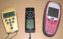
- Cellular telephony: clock synchronization enables time transfer, which is critical for synchronizing its spreading codes with other base stations to facilitate inter-cell handoff and support hybrid GPS/cellular position detection for mobile emergency calls and other applications. The first handsets with integrated GPS launched in the late 1990s. The U.S. Federal Communications Commission (FCC) mandated the feature in either the handset or in the towers (for use in triangulation) in 2002 so emergency services could locate 911 callers. Third-party software developers later gained access to GPS APIs from Nextel upon launch, followed by Sprint in 2006, and Verizon soon thereafter.
- Clock synchronization: the accuracy of GPS time signals (±10 ns)[83] is second only to the atomic clocks they are based on.
- Disaster relief/emergency services: many emergency services depend upon GPS for location and timing capabilities.
- GPS-equipped radiosondes and dropsondes: measure and calculate the atmospheric pressure, wind speed and direction up to 27 km from the Earth's surface.
- Radio occultation for weather and atmospheric science applications.[84]
- Fleet tracking: used to identify, locate and maintain contact reports with one or more fleet vehicles in real-time.
- Geofencing: vehicle tracking systems, person tracking systems, and pet tracking systems use GPS to locate devices that are attached to or carried by a person, vehicle, or pet. The application can provide continuous tracking and send notifications if the target leaves a designated (or "fenced-in") area.[85]
- Geotagging: applies location coordinates to digital objects such as photographs (in Exif data) and other documents for purposes such as creating map overlays with devices like Nikon GP-1
- GPS aircraft tracking
- GPS for mining: the use of RTK GPS has significantly improved several mining operations such as drilling, shoveling, vehicle tracking, and surveying. RTK GPS provides centimeter-level positioning accuracy.
- GPS data mining: It is possible to aggregate GPS data from multiple users to understand movement patterns, common trajectories and interesting locations.[86]
- GPS tours: location determines what content to display; for instance, information about an approaching point of interest.
- Navigation: navigators value digitally precise velocity and orientation measurements.
- Phasor measurements: GPS enables highly accurate timestamping of power system measurements, making it possible to compute phasors.
- Recreation: for example, Geocaching, Geodashing, GPS drawing, waymarking, and other kinds of location based mobile games.
- Robotics: self-navigating, autonomous robots using a GPS sensors, which calculate latitude, longitude, time, speed, and heading.
- Sport: used in football and rugby for the control and analysis of the training load.[87]
- Surveying: surveyors use absolute locations to make maps and determine property boundaries.
- Tectonics: GPS enables direct fault motion measurement of earthquakes. Between earthquakes GPS can be used to measure crustal motion and deformation[88] to estimate seismic strain buildup for creating seismic hazard maps.
- Telematics: GPS technology integrated with computers and mobile communications technology in automotive navigation systems.
Restrictions on civilian use
The U.S. government controls the export of some civilian receivers. All GPS receivers capable of functioning above 18 km (60,000 feet) altitude and 515 m/s (1,000 knots), or designed or modified for use with unmanned air vehicles like, e.g., ballistic or cruise missile systems, are classified as munitions (weapons)—which means they require State Department export licenses.[89]
This rule applies even to otherwise purely civilian units that only receive the L1 frequency and the C/A (Coarse/Acquisition) code.
Disabling operation above these limits exempts the receiver from classification as a munition. Vendor interpretations differ. The rule refers to operation at both the target altitude and speed, but some receivers stop operating even when stationary. This has caused problems with some amateur radio balloon launches that regularly reach 30 km (100,000 feet).
These limits only apply to units or components exported from the USA. A growing trade in various components exists, including GPS units from other countries. These are expressly sold as ITAR-free.
Military
_bombs_in_the_forward_mess_decks.jpg)

As of 2009, military GPS applications include:
- Navigation: Soldiers use GPS to find objectives, even in the dark or in unfamiliar territory, and to coordinate troop and supply movement. In the United States armed forces, commanders use the Commanders Digital Assistant and lower ranks use the Soldier Digital Assistant.[90]
- Target tracking: Various military weapons systems use GPS to track potential ground and air targets before flagging them as hostile. These weapon systems pass target coordinates to precision-guided munitions to allow them to engage targets accurately. Military aircraft, particularly in air-to-ground roles, use GPS to find targets.
- Missile and projectile guidance: GPS allows accurate targeting of various military weapons including ICBMs, cruise missiles, precision-guided munitions and Artillery projectiles. Embedded GPS receivers able to withstand accelerations of 12,000 g or about 118 km/s2 have been developed for use in 155-millimeter (6.1 in) howitzer shells.[91]
- Search and rescue.
- Reconnaissance: Patrol movement can be managed more closely.
- GPS satellites carry a set of nuclear detonation detectors consisting of an optical sensor (Y-sensor), an X-ray sensor, a dosimeter, and an electromagnetic pulse (EMP) sensor (W-sensor), that form a major portion of the United States Nuclear Detonation Detection System.[92][93] General William Shelton has stated that future satellites may drop this feature to save money.[94]
GPS type navigation was first used in war in the 1991 Persian Gulf War, before GPS was fully developed in 1995, to assist Coalition Forces to navigate and perform maneuvers in the war. The war also demonstrated the vulnerability of GPS to being jammed, when Iraqi forces added noise to the weak GPS signal transmission to protect Iraqi targets.[95]
Communication
The navigational signals transmitted by GPS satellites encode a variety of information including satellite positions, the state of the internal clocks, and the health of the network. These signals are transmitted on two separate carrier frequencies that are common to all satellites in the network. Two different encodings are used: a public encoding that enables lower resolution navigation, and an encrypted encoding used by the U.S. military.
Message format
GPS message format Subframes Description 1 Satellite clock,
GPS time relationship2–3 Ephemeris
(precise satellite orbit)4–5 Almanac component
(satellite network synopsis,
error correction)
Each GPS satellite continuously broadcasts a navigation message on L1 (C/A and P/Y) and L2 (P/Y) frequencies at a rate of 50 bits per second (see bitrate). Each complete message takes 750 seconds (12 1/2 minutes) to complete. The message structure has a basic format of a 1500-bit-long frame made up of five subframes, each subframe being 300 bits (6 seconds) long. Subframes 4 and 5 are subcommutated 25 times each, so that a complete data message requires the transmission of 25 full frames. Each subframe consists of ten words, each 30 bits long. Thus, with 300 bits in a subframe times 5 subframes in a frame times 25 frames in a message, each message is 37,500 bits long. At a transmission rate of 50-bit/s, this gives 750 seconds to transmit an entire almanac message (GPS). Each 30-second frame begins precisely on the minute or half-minute as indicated by the atomic clock on each satellite.[96]
The first subframe of each frame encodes the week number and the time within the week,[97] as well as the data about the health of the satellite. The second and the third subframes contain the ephemeris – the precise orbit for the satellite. The fourth and fifth subframes contain the almanac, which contains coarse orbit and status information for up to 32 satellites in the constellation as well as data related to error correction. Thus, to obtain an accurate satellite location from this transmitted message, the receiver must demodulate the message from each satellite it includes in its solution for 18 to 30 seconds. To collect all transmitted almanacs, the receiver must demodulate the message for 732 to 750 seconds or 12 1/2 minutes.[98]
All satellites broadcast at the same frequencies, encoding signals using unique code division multiple access (CDMA) so receivers can distinguish individual satellites from each other. The system uses two distinct CDMA encoding types: the coarse/acquisition (C/A) code, which is accessible by the general public, and the precise (P(Y)) code, which is encrypted so that only the U.S. military and other NATO nations who have been given access to the encryption code can access it.[99]
The ephemeris is updated every 2 hours and is generally valid for 4 hours, with provisions for updates every 6 hours or longer in non-nominal conditions. The almanac is updated typically every 24 hours. Additionally, data for a few weeks following is uploaded in case of transmission updates that delay data upload.
Satellite frequencies
GPS frequency overview Band Frequency Description L1 1575.42 MHz Coarse-acquisition (C/A) and encrypted precision (P(Y)) codes, plus the L1 civilian (L1C) and military (M) codes on future Block III satellites. L2 1227.60 MHz P(Y) code, plus the L2C and military codes on the Block IIR-M and newer satellites. L3 1381.05 MHz Used for nuclear detonation (NUDET) detection. L4 1379.913 MHz Being studied for additional ionospheric correction. L5 1176.45 MHz Proposed for use as a civilian safety-of-life (SoL) signal.
All satellites broadcast at the same two frequencies, 1.57542 GHz (L1 signal) and 1.2276 GHz (L2 signal). The satellite network uses a CDMA spread-spectrum technique where the low-bitrate message data is encoded with a high-rate pseudo-random (PRN) sequence that is different for each satellite. The receiver must be aware of the PRN codes for each satellite to reconstruct the actual message data. The C/A code, for civilian use, transmits data at 1.023 million chips per second, whereas the P code, for U.S. military use, transmits at 10.23 million chips per second. The actual internal reference of the satellites is 10.22999999543 MHz to compensate for relativistic effects[100][101] that make observers on the Earth perceive a different time reference with respect to the transmitters in orbit. The L1 carrier is modulated by both the C/A and P codes, while the L2 carrier is only modulated by the P code.[71] The P code can be encrypted as a so-called P(Y) code that is only available to military equipment with a proper decryption key. Both the C/A and P(Y) codes impart the precise time-of-day to the user.
The L3 signal at a frequency of 1.38105 GHz is used to transmit data from the satellites to ground stations. This data is used by the United States Nuclear Detonation (NUDET) Detection System (USNDS) to detect, locate, and report nuclear detonations (NUDETs) in the Earth's atmosphere and near space.[102] One usage is the enforcement of nuclear test ban treaties.
The L4 band at 1.379913 GHz is being studied for additional ionospheric correction.
The L5 frequency band at 1.17645 GHz was added in the process of GPS modernization. This frequency falls into an internationally protected range for aeronautical navigation, promising little or no interference under all circumstances. The first Block IIF satellite that provides this signal was launched in 2010.[103] The L5 consists of two carrier components that are in phase quadrature with each other. Each carrier component is bi-phase shift key (BPSK) modulated by a separate bit train. "L5, the third civil GPS signal, will eventually support safety-of-life applications for aviation and provide improved availability and accuracy."[104]
A conditional waiver has recently (2011-01-26) been granted to LightSquared to operate a terrestrial broadband service near the L1 band. Although LightSquared had applied for a license to operate in the 1525 to 1559 band as early as 2003 and it was put out for public comment, the FCC asked LightSquared to form a study group with the GPS community to test GPS receivers and identify issue that might arise due to the larger signal power from the LightSquared terrestrial network. The GPS community had not objected to the LightSquared (formerly MSV and SkyTerra) applications until November 2010, when LightSquared applied for a modification to its Ancillary Terrestrial Component (ATC) authorization. This filing (SAT-MOD-20101118-00239) amounted to a request to run several orders of magnitude more power in the same frequency band for terrestrial base stations, essentially repurposing what was supposed to be a "quiet neighborhood" for signals from space as the equivalent of a cellular network. Testing in the first half of 2011 has demonstrated that the impact of the lower 10 MHz of spectrum is minimal to GPS devices (less than 1% of the total GPS devices are affected). The upper 10 MHz intended for use by LightSquared may have some impact on GPS devices. There is some concern that this may seriously degrade the GPS signal for many consumer uses.[105][106] Aviation Week magazine reports that the latest testing (June 2011) confirms "significant jamming" of GPS by LightSquared's system.[107]
Demodulation and decoding

Because all of the satellite signals are modulated onto the same L1 carrier frequency, the signals must be separated after demodulation. This is done by assigning each satellite a unique binary sequence known as a Gold code. The signals are decoded after demodulation using addition of the Gold codes corresponding to the satellites monitored by the receiver.[108][109]
If the almanac information has previously been acquired, the receiver picks the satellites to listen for by their PRNs, unique numbers in the range 1 through 32. If the almanac information is not in memory, the receiver enters a search mode until a lock is obtained on one of the satellites. To obtain a lock, it is necessary that there be an unobstructed line of sight from the receiver to the satellite. The receiver can then acquire the almanac and determine the satellites it should listen for. As it detects each satellite's signal, it identifies it by its distinct C/A code pattern. There can be a delay of up to 30 seconds before the first estimate of position because of the need to read the ephemeris data.
Processing of the navigation message enables the determination of the time of transmission and the satellite position at this time. For more information see Demodulation and Decoding, Advanced.
Navigation equations
Problem description
The receiver uses messages received from satellites to determine the satellite positions and time sent. The x, y, and z components of satellite position and the time sent are designated as [xi, yi, zi, si] where the subscript i denotes the satellite and has the value 1, 2, ..., n, where n ≥ 4. When the time of message reception indicated by the on-board receiver clock is t̃i, the true reception time is ti = t̃i − b, where b is the receiver's clock bias from the much more accurate GPS system clocks employed by the satellites. The receiver clock bias is the same for all received satellite signals (assuming the satellite clocks are all perfectly synchronized). The message's transit time is t̃i − b − si, where si is the satellite time. Assuming the message traveled at the speed of light, c, the distance traveled is (t̃i − b − si) c.
For n satellites, the equations to satisfy are:
![(x-x_{i})^{2}+(y-y_{i})^{2}+(z-z_{i})^{2}={\bigl (}[{\tilde {t}}_{i}-b-s_{i}]c{\bigr )}^{2},\;i=1,2,\dots ,n](../I/m/0867a57a40a04e90097022c3aaaf04fa00f43fb6.svg)
or in terms of pseudoranges, , as


Since the equations have four unknowns [x, y, z, b]—the three components of GPS receiver position and the clock bias—signals from at least four satellites are necessary to attempt solving these equations. They can be solved by algebraic or numerical methods. Existence and uniqueness of GPS solutions are discussed by Abell and Chaffee.[57] When n is greater than 4 this system is overdetermined and a fitting method must be used.
With each combination of satellites, GDOP quantities can be calculated based on the relative sky directions of the satellites used.[112] The receiver location is expressed in a specific coordinate system, such as latitude and longitude using the WGS 84 geodetic datum or a country-specific system.[113]
Geometric interpretation
The GPS equations can be solved by numerical and analytical methods. Geometrical interpretations can enhance the understanding of these solution methods.
Spheres
The measured ranges, called pseudoranges, contain clock errors. In a simplified idealization in which the ranges are synchronized, these true ranges represent the radii of spheres, each centered on one of the transmitting satellites. The solution for the position of the receiver is then at the intersection of the surfaces of three of these spheres.[114] If more than the minimum number of ranges is available, a near intersection of more than three sphere surfaces could be found via, e.g. least squares.
Hyperboloids
If the distance traveled between the receiver and satellite i and the distance traveled between the receiver and satellite j are subtracted, the result is (t̃i − si) c − (t̃j − sj) c, which only involves known or measured quantities. The locus of points having a constant difference in distance to two points (here, two satellites) is a hyperboloid (see Multilateration). Thus, from four or more measured reception times, the receiver can be placed at the intersection of the surfaces of three or more hyperboloids.[57][58]
Spherical cones
The solution space [x, y, z, b] can be seen as a four-dimensional geometric space. In that case each of the equations describes a spherical cone,[115] with the cusp located at the satellite, and the base a sphere around the satellite. The receiver is at the intersection of four or more of such cones.
Solution methods
Least squares
When more than four satellites are available, the calculation can use the four best, or more than four simultaneously (up to all visible satellites), depending on the number of receiver channels, processing capability, and geometric dilution of precision (GDOP).
Using more than four involves an over-determined system of equations with no unique solution; such a system can be solved by a least-squares or weighted least squares method.[110]

Iterative
Both the equations for four satellites, or the least squares equations for more than four, are non-linear and need special solution methods. A common approach is by iteration on a linearized form of the equations, such as the Gauss–Newton algorithm.
The GPS system was initially developed assuming use of a numerical least-squares solution method—i.e., before closed-form solutions were found.
Closed-form
One closed-form solution to the above set of equations was developed by S. Bancroft.[111][116] Its properties are well known;[57][58][117] in particular, proponents claim it is superior in low-GDOP situations, compared to iterative least squares methods.[116]
Bancroft's method is algebraic, as opposed to numerical, and can be used for four or more satellites. When four satellites are used, the key steps are inversion of a 4x4 matrix and solution of a single-variable quadratic equation. Bancroft's method provides one or two solutions for the unknown quantities. When there are two (usually the case), only one is a near-Earth sensible solution.[111]
When a receiver uses more than four satellites for a solution, Bancroft uses the generalized inverse (i.e., the pseudoinverse) to find a solution. However, a case has been made that iterative methods (e.g., Gauss–Newton algorithm) for solving over-determined non-linear least squares (NLLS) problems generally provide more accurate solutions.[118]
Leick et al. (2015) states that "Bancroft's (1985) solution is a very early, if not the first, closed-form solution."[119] Other closed-form solutions were published afterwards,[120][121] although their adoption in practice is unclear.
Error sources and analysis
GPS error analysis examines error sources in GPS results and the expected size of those errors. GPS makes corrections for receiver clock errors and other effects, but some residual errors remain uncorrected. Error sources include signal arrival time measurements, numerical calculations, atmospheric effects (ionospheric/tropospheric delays), ephemeris and clock data, multipath signals, and natural and artificial interference. Magnitude of residual errors from these sources depends on geometric dilution of precision. Artificial errors may result from jamming devices and threaten ships and aircraft[122] or from intentional signal degradation through selective availability, which limited accuracy to ~6–12 m, but has been switched off since May 1, 2000.[123][124]
Accuracy enhancement and surveying
Augmentation
Integrating external information into the calculation process can materially improve accuracy. Such augmentation systems are generally named or described based on how the information arrives. Some systems transmit additional error information (such as clock drift, ephemera, or ionospheric delay), others characterize prior errors, while a third group provides additional navigational or vehicle information.
Examples of augmentation systems include the Wide Area Augmentation System (WAAS), European Geostationary Navigation Overlay Service (EGNOS), Differential GPS (DGPS), inertial navigation systems (INS) and Assisted GPS. The standard accuracy of about 15 meters (49 feet) can be augmented to 3–5 meters (9.8–16.4 ft) with DGPS, and to about 3 meters (9.8 feet) with WAAS.[125]
Precise monitoring
Accuracy can be improved through precise monitoring and measurement of existing GPS signals in additional or alternate ways.
The largest remaining error is usually the unpredictable delay through the ionosphere. The spacecraft broadcast ionospheric model parameters, but some errors remain. This is one reason GPS spacecraft transmit on at least two frequencies, L1 and L2. Ionospheric delay is a well-defined function of frequency and the total electron content (TEC) along the path, so measuring the arrival time difference between the frequencies determines TEC and thus the precise ionospheric delay at each frequency.
Military receivers can decode the P(Y) code transmitted on both L1 and L2. Without decryption keys, it is still possible to use a codeless technique to compare the P(Y) codes on L1 and L2 to gain much of the same error information. However, this technique is slow, so it is currently available only on specialized surveying equipment. In the future, additional civilian codes are expected to be transmitted on the L2 and L5 frequencies (see GPS modernization). All users will then be able to perform dual-frequency measurements and directly compute ionospheric delay errors.
A second form of precise monitoring is called Carrier-Phase Enhancement (CPGPS). This corrects the error that arises because the pulse transition of the PRN is not instantaneous, and thus the correlation (satellite–receiver sequence matching) operation is imperfect. CPGPS uses the L1 carrier wave, which has a period of , which is about one-thousandth of the C/A Gold code bit period of , to act as an additional clock signal and resolve the uncertainty. The phase difference error in the normal GPS amounts to 2–3 meters (7–10 ft) of ambiguity. CPGPS working to within 1% of perfect transition reduces this error to 3 centimeters (1.2 in) of ambiguity. By eliminating this error source, CPGPS coupled with DGPS normally realizes between 20–30 centimeters (8–12 in) of absolute accuracy.


Relative Kinematic Positioning (RKP) is a third alternative for a precise GPS-based positioning system. In this approach, determination of range signal can be resolved to a precision of less than 10 centimeters (4 in). This is done by resolving the number of cycles that the signal is transmitted and received by the receiver by using a combination of differential GPS (DGPS) correction data, transmitting GPS signal phase information and ambiguity resolution techniques via statistical tests—possibly with processing in real-time (real-time kinematic positioning, RTK).
Timekeeping
Leap seconds
While most clocks derive their time from Coordinated Universal Time (UTC), the atomic clocks on the satellites are set to GPS time (GPST; see the page of United States Naval Observatory). The difference is that GPS time is not corrected to match the rotation of the Earth, so it does not contain leap seconds or other corrections that are periodically added to UTC. GPS time was set to match UTC in 1980, but has since diverged. The lack of corrections means that GPS time remains at a constant offset with International Atomic Time (TAI) (TAI − GPS = 19 seconds). Periodic corrections are performed to the on-board clocks to keep them synchronized with ground clocks.[126]
The GPS navigation message includes the difference between GPS time and UTC. As of July 2015, GPS time is 17 seconds ahead of UTC because of the leap second added to UTC on June 30, 2015.[127][128] Receivers subtract this offset from GPS time to calculate UTC and specific timezone values. New GPS units may not show the correct UTC time until after receiving the UTC offset message. The GPS-UTC offset field can accommodate 255 leap seconds (eight bits).
Accuracy
GPS time is theoretically accurate to about 14 nanoseconds.[129] However, most receivers lose accuracy in the interpretation of the signals and are only accurate to 100 nanoseconds.[130][131]
Format
As opposed to the year, month, and day format of the Gregorian calendar, the GPS date is expressed as a week number and a seconds-into-week number. The week number is transmitted as a ten-bit field in the C/A and P(Y) navigation messages, and so it becomes zero again every 1,024 weeks (19.6 years). GPS week zero started at 00:00:00 UTC (00:00:19 TAI) on January 6, 1980, and the week number became zero again for the first time at 23:59:47 UTC on August 21, 1999 (00:00:19 TAI on August 22, 1999). To determine the current Gregorian date, a GPS receiver must be provided with the approximate date (to within 3,584 days) to correctly translate the GPS date signal. To address this concern the modernized GPS navigation message uses a 13-bit field that only repeats every 8,192 weeks (157 years), thus lasting until the year 2137 (157 years after GPS week zero).
Carrier phase tracking (surveying)
Another method that is used in surveying applications is carrier phase tracking. The period of the carrier frequency multiplied by the speed of light gives the wavelength, which is about 0.19 meters for the L1 carrier. Accuracy within 1% of wavelength in detecting the leading edge reduces this component of pseudorange error to as little as 2 millimeters. This compares to 3 meters for the C/A code and 0.3 meters for the P code.
However, 2 millimeter accuracy requires measuring the total phase—the number of waves multiplied by the wavelength plus the fractional wavelength, which requires specially equipped receivers. This method has many surveying applications. It is accurate enough for real-time tracking of the very slow motions of tectonic plates, typically 0–100 mm (0–4 inches) per year.
Triple differencing followed by numerical root finding, and a mathematical technique called least squares can estimate the position of one receiver given the position of another. First, compute the difference between satellites, then between receivers, and finally between epochs. Other orders of taking differences are equally valid. Detailed discussion of the errors is omitted.
The satellite carrier total phase can be measured with ambiguity as to the number of cycles. Let denote the phase of the carrier of satellite j measured by receiver i at time . This notation shows the meaning of the subscripts i, j, and k. The receiver (r), satellite (s), and time (t) come in alphabetical order as arguments of and to balance readability and conciseness, let be a concise abbreviation. Also we define three functions, :, which return differences between receivers, satellites, and time points, respectively. Each function has variables with three subscripts as its arguments. These three functions are defined below. If is a function of the three integer arguments, i, j, and k then it is a valid argument for the functions, :, with the values defined as


- ,
- , and
- .


Also if are valid arguments for the three functions and a and b are constants then is a valid argument with values defined as


- ,
- , and
- .


Receiver clock errors can be approximately eliminated by differencing the phases measured from satellite 1 with that from satellite 2 at the same epoch.[132] This difference is designated as

Double differencing[133] computes the difference of receiver 1's satellite difference from that of receiver 2. This approximately eliminates satellite clock errors. This double difference is:

Triple differencing[134] subtracts the receiver difference from time 1 from that of time 2. This eliminates the ambiguity associated with the integral number of wavelengths in carrier phase provided this ambiguity does not change with time. Thus the triple difference result eliminates practically all clock bias errors and the integer ambiguity. Atmospheric delay and satellite ephemeris errors have been significantly reduced. This triple difference is:

Triple difference results can be used to estimate unknown variables. For example, if the position of receiver 1 is known but the position of receiver 2 unknown, it may be possible to estimate the position of receiver 2 using numerical root finding and least squares. Triple difference results for three independent time pairs may be sufficient to solve for receiver 2's three position components. This may require a numerical procedure.[135][136] An approximation of receiver 2's position is required to use such a numerical method. This initial value can probably be provided from the navigation message and the intersection of sphere surfaces. Such a reasonable estimate can be key to successful multidimensional root finding. Iterating from three time pairs and a fairly good initial value produces one observed triple difference result for receiver 2's position. Processing additional time pairs can improve accuracy, overdetermining the answer with multiple solutions. Least squares can estimate an overdetermined system. Least squares determines the position of receiver 2 that best fits the observed triple difference results for receiver 2 positions under the criterion of minimizing the sum of the squares.
Regulatory spectrum issues concerning GPS receivers
In the United States, GPS receivers are regulated under the Federal Communications Commission's (FCC) Part 15 rules. As indicated in the manuals of GPS-enabled devices sold in the United States, as a Part 15 device, it "must accept any interference received, including interference that may cause undesired operation."[137] With respect to GPS devices in particular, the FCC states that GPS receiver manufacturers, "must use receivers that reasonably discriminate against reception of signals outside their allocated spectrum."[138] For the last 30 years, GPS receivers have operated next to the Mobile Satellite Service band, and have discriminated against reception of mobile satellite services, such as Inmarsat, without any issue.
The spectrum allocated for GPS L1 use by the FCC is 1559 to 1610 MHz, while the spectrum allocated for satellite-to-ground use owned by Lightsquared is the Mobile Satellite Service band.[139] Since 1996, the FCC has authorized licensed use of the spectrum neighboring the GPS band of 1525 to 1559 MHz to the Virginia company LightSquared. On March 1, 2001, the FCC received an application from LightSquared's predecessor, Motient Services to use their allocated frequencies for an integrated satellite-terrestrial service.[140] In 2002, the U.S. GPS Industry Council came to an out-of-band-emissions (OOBE) agreement with LightSquared to prevent transmissions from LightSquared's ground-based stations from emitting transmissions into the neighboring GPS band of 1559 to 1610 MHz.[141] In 2004, the FCC adopted the OOBE agreement in its authorization for LightSquared to deploy a ground-based network ancillary to their satellite system – known as the Ancillary Tower Components (ATCs) – "We will authorize MSS ATC subject to conditions that ensure that the added terrestrial component remains ancillary to the principal MSS offering. We do not intend, nor will we permit, the terrestrial component to become a stand-alone service."[142] This authorization was reviewed and approved by the U.S. Interdepartment Radio Advisory Committee, which includes the U.S. Department of Agriculture, U.S. Air Force, U.S. Army, U.S. Coast Guard, Federal Aviation Administration, National Aeronautics and Space Administration, Interior, and U.S. Department of Transportation.[143]
In January 2011, the FCC conditionally authorized LightSquared's wholesale customers—such as Best Buy, Sharp, and C Spire—to only purchase an integrated satellite-ground-based service from LightSquared and re-sell that integrated service on devices that are equipped to only use the ground-based signal using LightSquared's allocated frequencies of 1525 to 1559 MHz.[144] In December 2010, GPS receiver manufacturers expressed concerns to the FCC that LightSquared's signal would interfere with GPS receiver devices[145] although the FCC's policy considerations leading up to the January 2011 order did not pertain to any proposed changes to the maximum number of ground-based LightSquared stations or the maximum power at which these stations could operate. The January 2011 order makes final authorization contingent upon studies of GPS interference issues carried out by a LightSquared led working group along with GPS industry and Federal agency participation. On February 14, 2012, the FCC initiated proceedings to vacate LightSquared's Conditional Waiver Order based on the NTIA's conclusion that there was currently no practical way to mitigate potential GPS interference.
GPS receiver manufacturers design GPS receivers to use spectrum beyond the GPS-allocated band. In some cases, GPS receivers are designed to use up to 400 MHz of spectrum in either direction of the L1 frequency of 1575.42 MHz, because mobile satellite services in those regions are broadcasting from space to ground, and at power levels commensurate with mobile satellite services.[146] However, as regulated under the FCC's Part 15 rules, GPS receivers are not warranted protection from signals outside GPS-allocated spectrum.[138] This is why GPS operates next to the Mobile Satellite Service band, and also why the Mobile Satellite Service band operates next to GPS. The symbiotic relationship of spectrum allocation ensures that users of both bands are able to operate cooperatively and freely.
The FCC adopted rules in February 2003 that allowed Mobile Satellite Service (MSS) licensees such as LightSquared to construct a small number of ancillary ground-based towers in their licensed spectrum to "promote more efficient use of terrestrial wireless spectrum."[147] In those 2003 rules, the FCC stated "As a preliminary matter, terrestrial [Commercial Mobile Radio Service (“CMRS”)] and MSS ATC are expected to have different prices, coverage, product acceptance and distribution; therefore, the two services appear, at best, to be imperfect substitutes for one another that would be operating in predominately different market segments... MSS ATC is unlikely to compete directly with terrestrial CMRS for the same customer base...". In 2004, the FCC clarified that the ground-based towers would be ancillary, noting that "We will authorize MSS ATC subject to conditions that ensure that the added terrestrial component remains ancillary to the principal MSS offering. We do not intend, nor will we permit, the terrestrial component to become a stand-alone service."[142] In July 2010, the FCC stated that it expected LightSquared to use its authority to offer an integrated satellite-terrestrial service to "provide mobile broadband services similar to those provided by terrestrial mobile providers and enhance competition in the mobile broadband sector."[148] However, GPS receiver manufacturers have argued that LightSquared's licensed spectrum of 1525 to 1559 MHz was never envisioned as being used for high-speed wireless broadband based on the 2003 and 2004 FCC ATC rulings making clear that the Ancillary Tower Component (ATC) would be, in fact, ancillary to the primary satellite component.[149] To build public support of efforts to continue the 2004 FCC authorization of LightSquared's ancillary terrestrial component vs. a simple ground-based LTE service in the Mobile Satellite Service band, GPS receiver manufacturer Trimble Navigation Ltd. formed the "Coalition To Save Our GPS."[150]
The FCC and LightSquared have each made public commitments to solve the GPS interference issue before the network is allowed to operate.[151][152] However, according to Chris Dancy of the Aircraft Owners and Pilots Association, airline pilots with the type of systems that would be affected "may go off course and not even realize it."[153] The problems could also affect the Federal Aviation Administration upgrade to the air traffic control system, United States Defense Department guidance, and local emergency services including 911.[153]
On February 14, 2012, the U.S. Federal Communications Commission (FCC) moved to bar LightSquared's planned national broadband network after being informed by the National Telecommunications and Information Administration (NTIA), the federal agency that coordinates spectrum uses for the military and other federal government entities, that "there is no practical way to mitigate potential interference at this time".[154][155] LightSquared is challenging the FCC's action.
Other systems

Other satellite navigation systems in use or various states of development include:
- GLONASS – Russia's global navigation system. Fully operational worldwide.
- Galileo – a global system being developed by the European Union and other partner countries, planned to be operational by 2016 (and fully deployed by 2020)
- Beidou – People's Republic of China's regional system, currently limited to Asia and the West Pacific,[156] global coverage planned to be operational by 2020[157][158]
- IRNSS (NAVIC) – India's regional navigation system, covering India and Northern Indian Ocean
- QZSS – Japanese regional system covering Asia and Oceania
See also
- GPS/INS
- GPS navigation software
- GPS navigation device
- Indoor positioning system
- Local Area Augmentation System
- Local positioning system
- Military invention
- Mobile phone tracking
- Navigation paradox
- Notice Advisory to Navstar Users
- S-GPS
- Wide Area Augmentation System
Notes
- ↑ Though there are many receiver manufacturers, they almost all use one of the chipsets produced for this purpose.
- ↑ Orbital periods and speeds are calculated using the relations 4π²R³ = T²GM and V²R = GM, where R = radius of orbit in metres, T = orbital period in seconds, V = orbital speed in m/s, G = gravitational constant ≈ 6.673×10⁻¹¹ Nm²/kg², M = mass of Earth ≈ 5.98×1024 kg.
- ↑ Approximately 8.6 times (in radius and length) when the moon is nearest (363 104 km ÷ 42 164 km) to 9.6 times when the moon is farthest (405 696 km ÷ 42 164 km).
References
- ↑ "Navstar GPS Space Segment/Navigation User Interfaces"
- ↑ "The Navstar Global Positioning System, hereafter referred to as GPS, is a space-based radionavigation system owned by the United States Government (USG) and operated by the United States Air Force (USAF)."
- ↑ "Wide Area Augmentation System (WAAS) Performance Standard", Section B.3, Abbreviations and Acronyms: "GPS: Global Positioning System (or Navstar Global Positioning System)"
- ↑ http://www.space.com/19794-navstar.html
- ↑ "What is a GPS?".
- ↑ Srivastava, Ishan (5 April 2014). "How Kargil spurred India to design own GPS". The Times of India. Retrieved 9 December 2014.
- ↑ National Research Council (U.S.). Committee on the Future of the Global Positioning System; National Academy of Public Administration (1995). The global positioning system: a shared national asset: recommendations for technical improvements and enhancements. National Academies Press. p. 16. ISBN 0-309-05283-1. Retrieved August 16, 2013., https://books.google.com/books?id=FAHk65slfY4C&pg=PA16
- ↑ O'Leary, Beth Laura; Darrin, Ann Garrison (2009). Handbook of Space Engineering, Archaeology, and Heritage. Hoboken: CRC Press. pp. 239–240. ISBN 9781420084320.
- 1 2 "Factsheets : GPS Advanced Control Segment (OCX)". Losangeles.af.mil. October 25, 2011. Retrieved November 6, 2011.
- ↑ "Russia Launches Three More GLONASS-M Space Vehicles". Inside GNSS. Retrieved December 26, 2008.
- ↑ GLONASS the future for all smartphones?
- ↑ Winterberg, Friedwardt (1956). "Relativistische Zeitdiiatation eines künstlichen Satelliten (Relativistic time dilation of an artificial satellite)". Astronautica Acta II (in German) (25). Retrieved 19 October 2014.
- ↑ "GPS and Relativity". Astronomy.ohio-state.edu. Retrieved November 6, 2011.
- ↑ Guier, William H.; Weiffenbach, George C. (1997). "Genesis of Satellite Navigation" (PDF). Johns Hopkins APL Technical Digest. 19 (1): 178–181.
- ↑ Steven Johnson (2010), Where good ideas come from, the natural history of innovation, New York: Riverhead Books
- ↑ Helen E. Worth; Mame Warren (2009). Transit to Tomorrow. Fifty Years of Space Research at The Johns Hopkins University Applied Physics Laboratory (PDF).
- 1 2 Catherine Alexandrow (April 2008). "The Story of GPS".
- ↑ DARPA: 50 Years of Bridging the Gap. April 2008.
- ↑ Howell, Elizabeth. "Navstar: GPS Satellite Network". SPACE.com. Retrieved February 14, 2013.
- ↑ Jerry Proc. "Omega". Jproc.ca. Retrieved December 8, 2009.
- ↑ "Why Did the Department of Defense Develop GPS?". Trimble Navigation Ltd. Archived from the original on October 18, 2007. Retrieved January 13, 2010.
- ↑ "Charting a Course Toward Global Navigation". The Aerospace Corporation. Archived from the original on November 1, 2002. Retrieved October 14, 2013.
- ↑ "A Guide to the Global Positioning System (GPS) — GPS Timeline". Radio Shack. Retrieved January 14, 2010.
- ↑ "GEODETIC EXPLORER-A Press Kit" (PDF). NASA. October 29, 1965. Retrieved 20 October 2015.
- ↑ "SECOR Chronology". Mark Wade's Encyclopedia Astronautica. Retrieved January 19, 2010.
- ↑ "MX Deployment Reconsidered." Retrieved: 7 June 2013.
- ↑ Michael Russell Rip; James M. Hasik (2002). The Precision Revolution: GPS and the Future of Aerial Warfare. Naval Institute Press. p. 65. ISBN 1-55750-973-5. Retrieved January 14, 2010.
- 1 2 Hegarty, Christopher J.; Chatre, Eric (December 2008). "Evolution of the Global Navigation SatelliteSystem (GNSS)". Proceedings of the IEEE: 1902–1917. doi:10.1109/JPROC.2008.2006090.
- ↑ "ICAO Completes Fact-Finding Investigation". International Civil Aviation Organization. Archived from the original on May 17, 2008. Retrieved September 15, 2008.
- ↑ "United States Updates Global Positioning System Technology". America.gov. February 3, 2006.
- ↑ Rumerman, Judy A. (2009). NASA Historical Data Book, Volume VII (PDF). NASA. p. 136.
- ↑ The Global Positioning System Assessing National Policies, by Scott Pace, Gerald P. Frost, Irving Lachow, David R. Frelinger, Donna Fossum, Don Wassem, Monica M. Pinto, Rand Corporation, 1995,Appendix B, GPS History, Chronology, and Budgets
- ↑ "GPS & Selective Availability Q&A" (PDF). NOAA]. Archived from the original (PDF) on September 21, 2005. Retrieved May 28, 2010.
- ↑ "GPS Accuracy". GPS.gov. GPS.gov. Retrieved 4 May 2015.
- ↑ E. Steitz, David. "NATIONAL POSITIONING, NAVIGATION AND TIMING ADVISORY BOARD NAMED". Retrieved March 22, 2007.
- ↑ GPS Wing Reaches GPS III IBR Milestone in Inside GNSS November 10, 2008
- ↑ GPS CONSTELLATION STATUS FOR 08/26/2015
- ↑ "Recap story: Three Atlas 5 launch successes in one month".
- ↑ "GPS almanacs". Navcen.uscg.gov. Retrieved October 15, 2010.
- ↑ Dietrich Schroeer; Mirco Elena (2000). Technology Transfer. Ashgate. p. 80. ISBN 0-7546-2045-X. Retrieved May 25, 2008.
- ↑ Michael Russell Rip; James M. Hasik (2002). The Precision Revolution: GPS and the Future of Aerial Warfare. Naval Institute Press. ISBN 1-55750-973-5. Retrieved May 25, 2008.
- ↑ "AF Space Command Chronology". USAF Space Command. Retrieved June 20, 2011.
- ↑ "FactSheet: 2nd Space Operations Squadron". USAF Space Command. Retrieved June 20, 2011.
- ↑ The Global Positioning System: Assessing National Policies, p.245. RAND corporation
- 1 2 "USNO NAVSTAR Global Positioning System". U.S. Naval Observatory. Retrieved January 7, 2011.
- ↑ National Archives and Records Administration. U.S. Global Positioning System Policy. March 29, 1996.
- ↑ "National Executive Committee for Space-Based Positioning, Navigation, and Timing". Pnt.gov. Archived from the original on May 28, 2010. Retrieved October 15, 2010.
- ↑ "Assisted-GPS Test Calls for 3G WCDMA Networks". 3g.co.uk. November 10, 2004. Retrieved November 24, 2010.
- ↑ "First Modernized GPS Satellite Built By Lockheed Martin Launched". Phys.org. Retrieved September 26, 2005.
- ↑ 010907 (September 17, 2007). "losangeles.af.mil". losangeles.af.mil. Retrieved October 15, 2010.
- ↑ Johnson, Bobbie (May 19, 2009). "GPS system 'close to breakdown'". The Guardian. London. Retrieved December 8, 2009.
- ↑ Coursey, David (May 21, 2009). "Air Force Responds to GPS Outage Concerns". ABC News. Retrieved May 22, 2009.
- ↑ "Air Force GPS Problem: Glitch Shows How Much U.S. Military Relies On GPS". Huffingtonpost.comm. June 1, 2010. Retrieved October 15, 2010.
- ↑ "Contract Award for Next Generation GPS Control Segment Announced". Retrieved December 14, 2012.
- ↑ United States Naval Research Laboratory. National Medal of Technology for GPS. November 21, 2005
- ↑ "Space Technology Hall of Fame, Inducted Technology: Global Positioning System (GPS)". Archived from the original on June 12, 2012.
- 1 2 3 4 Abel, J.S. and Chaffee, J.W., "Existence and uniqueness of GPS solutions", IEEE Transactions on Aerospace and Electronic Systems, vol:26, no:6, p:748-53, Sept. 1991.
- 1 2 3 Fang, B.T., "Comments on "Existence and uniqueness of GPS solutions" by J.S. Abel and J.W. Chaffee", IEEE Transactions on Aerospace and Electronic Systems, vol:28 , no:4, Oct. 1992.
- ↑ Grewal, Mohinder S.; Weill, Lawrence R.; Andrews, Angus P. (2007). Global Positioning Systems, Inertial Navigation, and Integration (2nd ed.). John Wiley & Sons. pp. 92–93. ISBN 0-470-09971-2., https://books.google.com/books?id=6P7UNphJ1z8C&pg=PA92
- ↑ Georg zur Bonsen; Daniel Ammann; Michael Ammann; Etienne Favey; Pascal Flammant (April 1, 2005). "Continuous Navigation Combining GPS with Sensor-Based Dead Reckoning". GPS World. Archived from the original on November 11, 2006.
- ↑ "NAVSTAR GPS User Equipment Introduction" (PDF). United States Government. Chapter 7
- ↑ "GPS Support Notes" (PDF). January 19, 2007. Archived from the original (PDF) on March 27, 2009. Retrieved November 10, 2008.
- ↑ John Pike. "GPS III Operational Control Segment (OCX)". Globalsecurity.org. Retrieved December 8, 2009.
- 1 2 "Global Positioning System". Gps.gov. Archived from the original on July 30, 2010. Retrieved June 26, 2010.
- ↑ Daly, P. "Navstar GPS and GLONASS: global satellite navigation systems" (PDF). IEEE.
- ↑ Dana, Peter H. (August 8, 1996). "GPS Orbital Planes" (GIF).
- ↑ GPS Overview from the NAVSTAR Joint Program Office. Retrieved December 15, 2006.
- ↑ What the Global Positioning System Tells Us about Relativity Archived January 4, 2007, at the Wayback Machine.. Retrieved January 2, 2007.
- ↑ "Archived copy". Archived from the original on October 22, 2011. Retrieved 2011-10-27.. Retrieved October 27, 2011
- ↑ "USCG Navcen: GPS Frequently Asked Questions". Retrieved January 31, 2007.
- 1 2 Thomassen, Keith. "How GPS Works". avionicswest.com. Archived from the original on March 30, 2016. Retrieved April 22, 2014.
- ↑ Samama, Nel (2008). Global Positioning: Technologies and Performance. John Wiley & Sons. p. 65. ISBN 0-470-24190-X., https://books.google.com/books?id=EyFrcnSRFFgC&pg=PA65
- ↑ Agnew, D.C.; Larson, K.M. (2007). "Finding the repeat times of the GPS constellation". GPS Solutions. Springer. 11 (1): 71–76. doi:10.1007/s10291-006-0038-4. This article from author's web site Archived February 16, 2008, at the Wayback Machine., with minor correction.
- ↑ "CURRENT GPS CONSTELLATION". U.S. Naval Observatory.
- ↑ Massatt, Paul; Wayne Brady (Summer 2002). "Optimizing performance through constellation management" (PDF). Crosslink: 17–21. Archived from the original on January 25, 2012.
- ↑ United States Coast Guard General GPS News 9–9–05
- ↑ USNO NAVSTAR Global Positioning System. Retrieved May 14, 2006.
- ↑ "GPS III Operational Control Segment (OCX)". GlobalSecurity.org.
- ↑ "The USA's GPS-III Satellites". Defense Industry Daily. October 13, 2011.
- ↑ "GPS Completes Next Generation Operational Control System PDR". Air Force Space Command News Service. September 14, 2011.
- ↑ "'Embarrassing to defend': US general blasts Raytheon's GPS control system a 'disaster'". RT. December 9, 2015.
- ↑ "Publications and Standards from the National Marine Electronics Association (NMEA)". National Marine Electronics Association. Retrieved June 27, 2008.
- ↑ "Common View GPS Time Transfer". nist.gov. Archived from the original on October 28, 2012. Retrieved July 23, 2011.
- ↑ "Using GPS to improve tropical cyclone forecasts". ucar.edu.
- ↑ "Spotlight GPS pet locator". Spotlightgps.com. Retrieved October 15, 2010.
- ↑ Khetarpaul, S., Chauhan, R., Gupta, S. K., Subramaniam, L. V., Nambiar, U. (2011). Mining GPS data to determine interesting locations. Proceedings of the 8th International Workshop on Information Integration on the Web.
- ↑ "The Use of GPS Tracking Technology in Australian Football". Retrieved 2016-09-25.
- ↑ "The Pacific Northwest Geodetic Array". cwu.edu.
- ↑ Arms Control Association.Missile Technology Control Regime. Retrieved May 17, 2006.
- ↑ Sinha, Vandana (July 24, 2003). "Commanders and Soldiers' GPS-receivers". Gcn.com. Retrieved October 13, 2009.
- ↑ "XM982 Excalibur Precision Guided Extended Range Artillery Projectile". GlobalSecurity.org. May 29, 2007. Retrieved September 26, 2007. (registration required (help)).
- ↑ Sandia National Laboratory's Nonproliferation programs and arms control technology.
- ↑ Dennis D. McCrady. "The GPS Burst Detector W-Sensor" (PDF). Sandia National Laboratories.
- ↑ "US Air Force Eyes Changes To National Security Satellite Programs.". Aviationweek.com. January 18, 2013. Retrieved September 28, 2013.
- ↑ Greenemeier, Larry. "GPS and the World's First "Space War"". Scientific American. Retrieved 2016-02-08.
- ↑ "Satellite message format". Gpsinformation.net. Retrieved October 15, 2010.
- ↑ Peter H. Dana. "GPS Week Number Rollover Issues". Retrieved August 12, 2013.
- ↑ "Interface Specification IS-GPS-200, Revision D: Navstar GPS Space Segment/Navigation User Interfaces" (PDF). Navstar GPS Joint Program Office. p. 103.
- ↑ Richharia, Madhavendra; Westbrook, Leslie David (2011). Satellite Systems for Personal Applications: Concepts and Technology. John Wiley & Sons. p. 443. ISBN 1-119-95610-2., https://books.google.com/books?id=MqPQ5CbgQ48C443
- ↑ Misra, Pratap; Enge, Per (2006). Global Positioning System. Signals, Measurements and Performance (2nd ed.). Ganga-Jamuna Press. p. 115. ISBN 0-9709544-1-7. Retrieved August 16, 2013.
- ↑ Borre, Kai; M. Akos, Dennis; Bertelsen, Nicolaj; Rinder, Peter; Jensen, Søren Holdt (2007). A Software-Defined GPS and Galileo Receiver. A single-Frequency Approach. Springer. p. 18. ISBN 0-8176-4390-7.
- ↑ TextGenerator Version 2.0. "United States Nuclear Detonation Detection System (USNDS)". Fas.org. Retrieved November 6, 2011.
- ↑ "First Block 2F GPS Satellite Launched, Needed to Prevent System Failure". DailyTech. Retrieved May 30, 2010.
- ↑ "Air Force Successfully Transmits an L5 Signal From GPS IIR-20(M) Satellite". LA AFB News Release. Retrieved June 20, 2011.
- ↑ "Federal Communications Commission Presented Evidence of GPS Signal Interference". GPS World. Archived from the original on October 11, 2011. Retrieved November 6, 2011.
- ↑ "Coalition to Save Our GPS". Saveourgps.org. Retrieved November 6, 2011.
- ↑ "LightSquared Tests Confirm GPS Jamming". Aviation Week. Archived from the original on August 12, 2011. Retrieved June 20, 2011.
- ↑ "GPS Almanacs, NANUS, and Ops Advisories (including archives)". GPS Almanac Information. United States Coast Guard. Retrieved September 9, 2009.
- ↑ "George, M., Hamid, M., and Miller A. [//web.archive.org/web/20071122063244/126 KB Gold Code Generators in Virtex Devices] at the Internet ArchivePDF
- 1 2 section 4 beginning on page 15 GEOFFREY BLEWITT: BASICS OF THE GPS TECHNIQUE
- 1 2 3 "Global Positioning Systems" (PDF). Archived from the original (PDF) on July 19, 2011. Retrieved October 15, 2010.
- ↑ Dana, Peter H. "Geometric Dilution of Precision (GDOP) and Visibility". University of Colorado at Boulder. Retrieved July 7, 2008.
- ↑ Peter H. Dana. "Receiver Position, Velocity, and Time". University of Colorado at Boulder. Retrieved July 7, 2008.
- ↑ "The Mathematics of GPS". siam.org. Archived from the original on March 16, 2005.
- ↑ "GPS Solutions: Closed Forms, Critical and Special Configurations of P4P".
- 1 2 Bancroft, S. (January 1985). "An Algebraic Solution of the GPS Equations". IEEE Transactions on Aerospace and Electronic Systems. AES-21: 56–59. Bibcode:1985ITAES..21...56B. doi:10.1109/TAES.1985.310538.
- ↑ Chaffee, J. and Abel, J., "On the Exact Solutions of Pseudorange Equations", IEEE Transactions on Aerospace and Electronic Systems, vol:30, no:4, pp: 1021–1030, 1994
- ↑ Sirola, Niilo, "Closed-form Algorithms in Mobile Positioning: Myths and Misconceptions", Proceedings of the 7th Workshop on Positioning, Navigation and Communication 2010 (WPNC'10), Dresden, March 2010. Retrieved November 10, 2014
- ↑ "GNSS Positioning Approaches – GPS Satellite Surveying, Fourth Edition – Leick – Wiley Online Library". wiley.com.
- ↑ Alfred Kleusberg, "Analytical GPS Navigation Solution", University of Stuttgart Research Compendium,1994
- ↑ Oszczak, B., "New Algorithm for GNSS Positioning Using System of Linear Equations," Proceedings of the 26th International Technical Meeting of The Satellite Division of the Institute of Navigation (ION GNSS+ 2013), Nashville, TN, September 2013, pp. 3560–3563.
- ↑ Attewill, Fred. (2013-02-13) Vehicles that use GPS jammers are big threat to aircraft. Metro.co.uk. Retrieved on 2013-08-02.
- ↑ "Frequently Asked Questions About Selective Availability". National Coordination Office for Space-Based Positioning, Navigation, and Timing (PNT). October 2001. Retrieved 2015-06-13.
Selective Availability ended a few minutes past midnight EDT after the end of May 1, 2000. The change occurred simultaneously across the entire satellite constellation.
- ↑ https://blackboard.vuw.ac.nz/bbcswebdav/pid-1444805-dt-content-rid-2193398_1/courses/2014.1.ESCI203/Esci203_2014_GPS_1.pdf (subscription required)
- ↑ McNamara, Joel (2008). GPS For Dummies. John Wiley & Sons. p. 59. ISBN 0-470-45785-6., https://books.google.com/books?id=Hbz4LYIrvuMC&pg=PA59
- ↑ "NAVSTAR GPS User Equipment Introduction" (PDF). Section 1.2.2
- ↑ "NOTICE ADVISORY TO NAVSTAR USERS (NANU) 2015086". Retrieved October 2015. Check date values in:
|access-date=(help) - ↑ "Notice Advisory to Navstar Users (NANU) 2012034". GPS Operations Center. May 30, 2012. Retrieved July 2, 2012.
- ↑ David W. Allan (1997). "The Science of Timekeeping" (PDF). Hewlett Packard. Archived (PDF) from the original on October 12, 2012.
- ↑ "The Role of GPS in Precise Time and Frequency Dissemination" (PDF). GPSworld. July–August 1990. Retrieved April 27, 2014.
- ↑ "GPS time accurate to 100 nanoseconds". Galleon. Retrieved October 12, 2012.
- ↑ "Between-Satellite Differencing". Gmat.unsw.edu.au. Retrieved October 15, 2010.
- ↑ "Double differencing". Gmat.unsw.edu.au. Retrieved October 15, 2010.
- ↑ "Triple differencing". Gmat.unsw.edu.au. Retrieved October 15, 2010.
- ↑ chapter on root finding and nonlinear sets of equations
- ↑ Preview of Root Finding. Books.google.com. 2007. ISBN 978-0-521-88068-8. Retrieved October 15, 2010.
- ↑ "2011 John Deere StarFire 3000 Operator Manual" (PDF). John Deere. Archived from the original (PDF) on January 5, 2012. Retrieved November 13, 2011.
- 1 2 "Federal Communications Commission Report and Order In the Matter of Fixed and Mobile Services in the Mobile Satellite Service Bands at 1525–1559 MHz and 1626.5–1660.5 MHz" (PDF). FCC.gov. April 6, 2011. Retrieved December 13, 2011.
- ↑ "Federal Communications Commission Table of Frequency Allocations" (PDF). FCC.gov. November 18, 2011. Retrieved December 13, 2011.
- ↑ "FCC Docket File Number: SATASG2001030200017, "Mobile Satellite Ventures LLC Application for Assignment and Modification of Licenses and for Authority to Launch and Operate a Next-Generation Mobile Satellite System"". FCC.gov. March 1, 2001. p. 9.
- ↑ "U.S. GPS Industry Council Petition to the FCC to adopt OOBE limits jointly proposed by MSV and the Industry Council". FCC.gov. September 4, 2003. Retrieved December 13, 2011.
- 1 2 "ORDER ON RECONSIDERATION" (PDF). Jul 3, 2003. Retrieved October 2015. Check date values in:
|access-date=(help) - ↑ "Statement of Julius P. Knapp, Chief, Office of Engineering and Technology, Federal Communications Commission" (PDF). gps.gov. September 15, 2011. p. 3. Retrieved December 13, 2011.
- ↑ "FCC Order, Granted LightSquared Subsidiary LLC, a Mobile Satellite Service licensee in the L-Band, a conditional waiver of the Ancillary Terrestrial Component "integrated service" rule" (PDF). Federal Communications Commission. FCC.Gov. January 26, 2011. Retrieved December 13, 2011.
- ↑ "Data Shows Disastrous GPS Jamming from FCC-Approved Broadcaster". gpsworld.com. February 1, 2011. Archived from the original on February 6, 2011. Retrieved February 10, 2011.
- ↑ "Javad Ashjaee GPS World webinar". gpsworld.com. December 8, 2011. Archived from the original on November 26, 2011. Retrieved December 13, 2011.
- ↑ "FCC Order permitting mobile satellite services providers to provide an ancillary terrestrial component (ATC) to their satellite systems" (PDF). Federal Communications Commission. FCC.gov. February 10, 2003. Retrieved December 13, 2011.
- ↑ "Federal Communications Commission Fixed and Mobile Services in the Mobile Satellite Service". Federal Communications Commission. FCC.gov. July 15, 2010. Retrieved December 13, 2011.
- ↑ Archived December 13, 2012, at the Wayback Machine.
- ↑ "Coalition to Save Our GPS". Saveourgps.org. Retrieved November 6, 2011.
- ↑ Jeff Carlisle (June 23, 2011). "Testimony of Jeff Carlisle, LightSquared Executive Vice President of Regulatory Affairs and Public Policy to U.S. House Subcommittee on Aviation and Subcommittee on Coast Guard and Maritime Transportation" (PDF). Archived from the original (PDF) on September 29, 2011. Retrieved December 13, 2011.
- ↑ Julius Genachowski (May 31, 2011). "FCC Chairman Genachowski Letter to Senator Charles Grassley" (PDF). Retrieved December 13, 2011.
- 1 2 Tessler, Joelle (April 7, 2011). "Internet network may jam GPS in cars, jets". The Sun News. Archived from the original on May 1, 2011. Retrieved April 7, 2011.
- ↑ FCC press release "Spokesperson Statement on NTIA Letter – LightSquared and GPS". February 14, 2012. Accessed 2013-03-03.
- ↑ Paul Riegler, FBT. "FCC Bars LightSquared Broadband Network Plan". February 14, 2012. Retrieved February 14, 2012.
- ↑ Beidou coverage
- ↑ "Beidou satellite navigation system to cover whole world in 2020". Eng.chinamil.com.cn. Retrieved October 15, 2010.
- ↑ Levin, Dan (March 23, 2009). "Chinese Square Off With Europe in Space". The New York Times. China. Retrieved November 6, 2011.
Further reading
- "NAVSTAR GPS User Equipment Introduction" (PDF). United States Coast Guard. September 1996.
- Parkinson; Spilker (1996). The global positioning system. American Institute of Aeronautics and Astronautics. ISBN 978-1-56347-106-3.
- Jaizki Mendizabal; Roc Berenguer; Juan Melendez (2009). GPS and Galileo. McGraw Hill. ISBN 978-0-07-159869-9.
- Nathaniel Bowditch (2002). The American Practical Navigator – Chapter 11 Satellite Navigation. United States government.
- Global Positioning System Open Courseware from MIT, 2012
External links
| Wikimedia Commons has media related to Global Positioning System. |
- Schriever Air Force Base – GPS Operations Center Responsible for operation of the Global Positioning System
- Global Positioning System at DMOZ
- FAA GPS FAQ
- GPS.gov—General public education website created by the U.S. Government
- USCG Navigation Center—Status of the GPS constellation, government policy, and links to other references; includes satellite almanac data.
- The GPS Program Office (GPS Wing)—Responsible for designing and acquiring the system on behalf of the United States Government.
- U.S. Army Corps of Engineers manual:"NAVSTAR HTML". Archived from the original on August 22, 2008. Retrieved 2010-06-06. and"PDF (22.6 MB, 328 pages)" (PDF). Archived from the original on June 25, 2008. Retrieved 2010-06-06.
- National Geodetic Survey Orbits for the Global Positioning System satellites in the Global Navigation Satellite System
- GPS PPS Performance Standard—The official Precise Positioning Service specification
- GPS and GLONASS Simulation (Java applet) Simulation and graphical depiction of space vehicle motion including computation of dilution of precision (DOP)
- Navipedia information on GPS—Wiki initiated by the European Space Agency
- Relativity Science Calculator – Explaining Global Positioning System
| Operational | |
|---|---|
| Historical | |
| In development | |
| GNSS augmentation | |
| GNSS augmentation historical | |
| Related topics | |
Part of a series of articles on cars | |||||||||||||||||||||||
| Body |
| ||||||||||||||||||||||
Exterior equipment |
| ||||||||||||||||||||||
| |||||||||||||||||||||||
| Active service & Aircraft designation |
| ||||||||||||||||||||||||||||||||||||||||||||||||||||||||||||||||||
|---|---|---|---|---|---|---|---|---|---|---|---|---|---|---|---|---|---|---|---|---|---|---|---|---|---|---|---|---|---|---|---|---|---|---|---|---|---|---|---|---|---|---|---|---|---|---|---|---|---|---|---|---|---|---|---|---|---|---|---|---|---|---|---|---|---|---|---|
| Space systems |
| ||||||||||||||||||||||||||||||||||||||||||||||||||||||||||||||||||
| Ground systems |
| ||||||||||||||||||||||||||||||||||||||||||||||||||||||||||||||||||
| Munitions |
| ||||||||||||||||||||||||||||||||||||||||||||||||||||||||||||||||||
| Small arms |
| ||||||||||||||||||||||||||||||||||||||||||||||||||||||||||||||||||
| Uniforms & other equipment |
| ||||||||||||||||||||||||||||||||||||||||||||||||||||||||||||||||||