Flyback transformer
A flyback transformer (FBT), also called a line output transformer (LOPT), is a special type of electrical transformer. It was initially designed to generate high voltage sawtooth signals at a relatively high frequency. In modern applications, it is used extensively in switched-mode power supplies for both low (3 V) and high voltage (over 10 kV) supplies.
History
The flyback transformer circuit was invented as a means of controlling the horizontal movement of the electron beam in a cathode ray tube (CRT). Unlike conventional transformers, a flyback transformer is not fed with a signal of the same waveshape as the intended output current. A convenient side effect of such a transformer is the considerable energy that is available in its magnetic circuit. This can be exploited using extra windings that can be used to provide power to operate other parts of the equipment. In particular, very high voltages are easily obtained using relatively few turns of winding which, once rectified, can provide the very high accelerating voltage for a CRT. Many more recent applications of such a transformer dispense with the need to produce high voltages and just use the device as a relatively efficient means of producing a wide range of lower voltages using a transformer much smaller than a conventional mains transformer would be.
Operation and usage
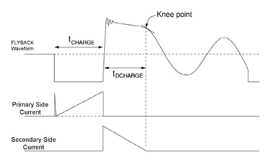
The primary winding of the flyback transformer is driven by a switch from a DC supply (usually a transistor). When the switch is switched on, the primary inductance causes the current to build up in a ramp. An integral diode connected in series with the secondary winding prevents the formation of secondary current that would eventually oppose the primary current ramp.[1]
When the switch is turned off, the current in the primary falls to zero. The energy stored in the magnetic core is released to the secondary as the magnetic field in the core collapses. The voltage in the output winding rises very quickly (usually less than a microsecond) until it is limited by the load conditions. Once the voltage reaches such level as to allow the secondary current to flow, then the current in the secondary winding begins to flow in the form of a descending ramp.
The cycle can then be repeated. If the secondary current is allowed to discharge completely to zero (no energy stored in the core), then it is said that the transformer works in discontinuous mode (DCM). When some energy is always stored in the core (and the current waveforms look trapezoidal rather than triangular), then this is continuous mode (CCM). This terminology is used especially in power supply transformers.
The low voltage output winding mirrors the sawtooth of the primary current and, e.g. for television purposes, has fewer turns than the primary, thus providing a higher current. This is a ramped and pulsed waveform that repeats at the horizontal (line) frequency of the display. The flyback (vertical portion of the sawtooth wave) can be a potential problem to the flyback transformer if the energy has nowhere to go: the faster a magnetic field collapses, the greater the induced voltage, which, if not controlled, can flash over the transformer terminals. The high frequency used permits the use of a much smaller transformer. In television sets, this high frequency is about 15 kilohertz (15.625 kHz for PAL, 15.734 kHz for NTSC), and vibrations from the transformer core caused by magnetostriction can often be heard as a high-pitched whine. In modern computer displays, the frequency can vary over a wide range, from about 30 kHz to 150 kHz.
The transformer can be equipped with extra windings whose sole purpose is to have a relatively large voltage pulse induced in them when the magnetic field collapses as the input switch is turned off. There is considerable energy stored in the magnetic field and coupling it out via extra windings helps it to collapse quickly, and avoids the voltage flash over that might otherwise occur. The pulse train coming from the flyback transformer windings is converted to direct current by a simple half wave rectifier. There is no point in using a full wave design as there are no corresponding pulses of opposite polarity. One turn of a winding often produces pulses of several volts. In older television designs, the transformer produced the required high voltage for the CRT accelerating voltage directly with the output rectified by a simple rectifier. In more modern designs, the rectifier is replaced by a voltage multiplier. Color television sets also have to use a regulator to control the high voltage. The earliest sets used a shunt vacuum tube regulator, but the introduction of solid state sets employed a simpler voltage dependant resistor. The rectified voltage is then used to supply the final anode of the cathode ray tube.
There are often auxiliary windings that produce lower voltages for driving other parts of the television circuitry. The voltage used to bias the varactor diodes in modern tuners is often derived from the flyback transformer ("Line OutPut Transformer" LOPT). In tube sets, a one or two-turn filament winding is located on the opposite side of the core as the HV secondary, used to drive the HV rectifier tube's heater.
Practical considerations
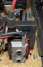
In modern displays, the LOPT, voltage multiplier and rectifier are often integrated into a single package on the main circuit board. There is usually a thickly insulated wire from the LOPT to the anode terminal (covered by a rubber cap) on the side of the picture tube.
One advantage of operating the transformer at the flyback frequency is that it can be much smaller and lighter than a comparable transformer operating at mains (line) frequency. Another advantage is that it provides a failsafe mechanism — should the horizontal deflection circuitry fail, the flyback transformer will cease operating and shut down the rest of the display, preventing the screen burn that would otherwise result from a stationary electron beam.
Construction
The primary is wound first around a ferrite rod, and then the secondary is wound around the primary. This arrangement minimizes the leakage inductance of the primary. Finally, a ferrite frame is wrapped around the primary/secondary assembly, closing the magnetic field lines. Between the rod and the frame is an air gap, which increases the reluctance. The secondary is wound layer by layer with enameled wire, and Mylar film between the layers. In this way parts of the wire with higher voltage between them have more dielectric material between them.
Applications
The flyback transformer is used in the operation of CRT-display devices such as television sets and CRT computer monitors. The voltage and frequency can each range over a wide scale depending on the device. For example, a large color TV CRT may require 20 to 50 kV with a horizontal scan rate of 15.734 kHz for NTSC devices. Unlike a power (or "mains") transformer which uses an alternating current of 50 or 60 hertz, a flyback transformer typically operates with switched currents at much higher frequencies in the range of 15 kHz to 50 kHz.
Failure and repair
Flyback transformers are a frequent source of failure in CRT displays. Often, the CRT itself is blamed when the display has actually experienced a flyback transformer failure. The high voltage present in the many turns of wire, with the thin insulation required for the transformer to be of reasonable size, can result in leakage between the windings. As the leakage heats the insulation, it carbonizes and increases conduction. In turn, heat and carbonization continue degrading the insulation until the leaked current is high enough for the high voltage to arc between the windings, and destroy the transformer (and sometimes other components in the display). As a result, replacement flyback transformers for almost every set on the market are available through dealers in electronic parts, typically for under $50. The problem is exacerbated by the tendency of the flyback to accumulate a coating of dust due to electrostatic attraction, which serves as a path to ground for leaks which might otherwise not be of sufficient magnitude to initiate the chain of events leading to destructive failure, as described.
As a result, occasional cleaning of the accumulated dust from the high voltage circuitry inside a television can be beneficial if proper precautions are taken — however the small amount of additional life that is gained for the flyback transformer rarely justifies the time and effort necessary. It is debated among technicians if displays installed in dirty, dusty locations experience more failures than those in cleaner locations, but many do say that dirty conditions contribute to malfunctions.
Another common failure mode is for one of the windings to develop a short circuit turn. This is often the high voltage winding with its small wire and thin enamel insulation. Once a short circuit turn occurs, the transformer is prevented from ringing (magnetically speaking) as the shorted turn "damps" the inductance. It is not possible to detect the shorted turn using conventional resistance measuring equipment.
In many recent televisions, after replacing the flyback transformer, the control firmware must be recalibrated to account for slight differences in performance between transformers in order to maintain accurate picture reproduction. In older televisions and monitors, these needed adjustments were performed by turning potentiometers inside, or on the back of the set to achieve optimal picture quality. Also, when flyback transformers fail, they frequently will also damage the horizontal output transistor that drives the flyback transformer, and sometimes even blow fuses in the low voltage power supply circuits.
Unless the owner of the display device has enough experience and knowledge to repair it themselves, the failure of a flyback transformer frequently condemns the device as unrepairable, because the cost of repair can be higher than the replacement cost. Although the cost of the flyback transformer — and other damaged parts — is relatively inexpensive, the labor time needed to disassemble, replace the parts, and then re-adjust the display can make the repair prohibitively expensive.
Safety considerations
A flyback transformer and its associated circuitry operate at very high voltages at low currents (<1mA-15mA), far beyond mains voltage. While most flybacks do not supply enough power to kill directly, the voltage they employ can cause violent muscle spasms if touched; and such spasms usually cause injury. A common injury that occurs when one is shocked is actually to be injured not as much by the shock itself, but when the victim's hand or arm is thrown back against other internal components in the display device. Therefore, only trained persons should touch or modify these devices, after first ensuring that the transformer is switched off and any stored energy has been safely discharged. The CRT attached to the flyback has an inherent capacitance which can hold a high voltage charge for more than a week after the power is switched off. Often, a high-resistance bleeder resistor is connected internally within the flyback transformer to ensure the charge is safely grounded when not in use, but many sets lack this, especially older models.
See also
Notes
- ↑ "Designing Flyback Transformers" (PDF). Keith Billings.
References
External links
- Driving flyback transformers
- U.S. Patent 3,665,288 - "Television sweep transformer" - Theodore J. Godawski