Flyback diode
A flyback diode (sometimes called a snubber diode, commutating diode, freewheeling diode, suppressor diode, suppression diode, clamp diode or catch diode[1]) is a diode used to eliminate flyback, which is the sudden voltage spike seen across an inductive load when its supply current is suddenly reduced or interrupted.
Working principle

In its most simplified form with a voltage source connected to an inductor with a switch, we have 2 states available. In the first steady-state, the switch has been closed for a long time such that the inductor has become fully energized and is behaving as though it were a short (Figure 1). Current is flowing "down" from the positive terminal of the voltage source to its negative terminal, through the inductor. When the switch is opened (Figure 2), the inductor will attempt to resist the sudden drop of current (dI/dt is large therefore V is large) by using its stored magnetic field energy to create its own voltage. An extremely large negative potential is created where there once was positive potential, and a positive potential is created where there was once negative potential. The switch, however, remains at the voltage of the power supply, but it is still in contact with the inductor pulling down a negative voltage. Since no connection is physically made to allow current to continue to flow (due to the switch being open), the large potential difference can cause electrons to "arc" across the air-gap of the open switch (or junction of a transistor). This is undesirable for the reasons mentioned above and must be prevented.
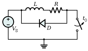
A flyback diode solves this starvation-arc problem by allowing the inductor to draw current from itself (thus, "flyback") in a continuous loop until the energy is dissipated through losses in the wire, the diode and the resistor (Figure 3). When the switch is closed the diode is reverse-biased against the power supply and doesn't exist in the circuit for practical purposes. However, when the switch is opened, the diode becomes forward-biased relative to the inductor (instead of the power supply as before), allowing it to conduct current in a circular loop from the positive potential at the bottom of the inductor to the negative potential at the top (assuming the power supply was supplying positive voltage at the top of the inductor prior to the switch being opened). The voltage across the inductor will merely be a function of the forward voltage drop of the flyback diode. Total time for dissipation can vary, but it will usually last for a few milliseconds.

In these images we observe classic signs of back EMF and its elimination through the use of a flyback diode (1N4007). The inductor in this case is a solenoid connected to a 24V DC power supply using 20 awg wire. Each waveform was taken using a digital oscilloscope set to trigger when the voltage across the inductor dipped below zero. In Figure 1 the voltage as measured across the switch bounces/spikes to around -300 V. In Figure 2, a flyback diode was added in antiparallel with the solenoid. Instead of spiking to -300 V, the flyback diode only allows approximately -1.4 V of potential to be built up (-1.4 V is a combination of the forward bias of the 1N4007 diode (1.1 V) and the foot of wiring separating the diode and the solenoid). The waveform in Figure 2 is much less bouncy than the waveform in Figure 1. In both cases, the total time for the solenoid to discharge is a few milliseconds.
Design
In an ideal flyback diode selection, one would seek a diode which has very large peak forward current capacity (to handle voltage transients without burning out the diode), low forward voltage drop, and a reverse breakdown voltage suited to the inductor's power supply. Depending on the application and equipment involved, some voltage surges can be upwards of 10 times the voltage of the power source, so it is critical not to underestimate the energy contained within an energized inductor.
When used with a DC coil relay, a flyback diode can cause delayed drop-out of the contacts when power is removed, due to the continued circulation of current in the relay coil and diode. When rapid opening of the contacts is important, a low-value resistor can be placed in series with the diode to help dissipate the coil energy faster, at the expense of higher voltage at the switch.
Schottky diodes are preferred in flyback diode applications for switching power converters, because they have the lowest forward drop (~0.2 V rather than >0.7 V for low currents) and are able to quickly respond to reverse bias (when the inductor is being re-energized). They therefore dissipate less energy while transferring energy from the inductor to a capacitor.
When the flyback diode is used to simply dissipate the inductive energy, as with a solenoid or motor, cheap 1N4001 and 1N5400 silicon diodes are used instead.
Induction at the opening of a contact
According to Lenz's law, if the current through an inductance changes, this inductance induces a voltage so the current will go on flowing as long as there is energy in the magnetic field. If the current can only flow through the air, the voltage is therefore so high that the air conducts. That is why in mechanically-switched circuits, the near-instantaneous dissipation which occurs without a flyback diode is often observed as an arc across the opening mechanical contacts. Energy is dissipated in this arc primarily as intense heat which causes undesirable premature erosion of the contacts. Another way to dissipate energy is through electromagnetic radiation.
Similarly, for non-mechanical solid state switching (i.e., a transistor), large voltage drops across an unactivated solid state switch can destroy the component in question (either instantaneously or through accelerated wear and tear).
Some energy is also lost from the system as a whole and from the arc as a broad spectrum of electromagnetic radiation, in the form of radio waves and light. These radio waves can cause undesirable clicks and pops on nearby radio receivers.
To minimise the antenna-like radiation of this electromagnetic energy from wires connected to the inductor, the flyback diode should be connected as physically close to the inductor as practicable. This approach also minimises those parts of the circuit that are subject to an unwanted high-voltage — a good engineering practice.
Derivation
The voltage at an inductor is, by the law of electromagnetic induction and the definition of inductance:

If there is no flyback diode but only something with a great resistance (such as the air between two metal contacts), say, R2, we will approximate it as:

If we open the switch and ignore VCC and R1, we get:

or

which is a differential equation with the solution:

We observe that the current will decrease faster if the resistance is high, such as with air.
Now if we open the switch with the diode in place, we only need to consider L1, R1 and D1. For I > 0, we can assume:

so:

which is:

whose solution is:

We can calculate the time it needs to switch off by determining for which t it is I(t) = 0.

Applications
Flyback diodes are commonly used when inductive loads are switched off by semiconductor devices: in relay drivers, H-bridge motor drivers, and so on. A switched-mode power supply also exploits this effect, but the energy is not dissipated to heat and instead used to pump a packet of additional charge into a capacitor, in order to supply power to a load.
See also
References
- ↑ hp9825.com; use of "catch" diode
External links
- Relay Technical Notes - American Zettler
- Relay Application Notes - TE Connectivity
- Relay RC Circuit - Evox Rifa
- Application Circuits of Miniature Signal Relays - NEC/Tokin
- "diode for relay coil spikes and motor shutoff spikes?" - sci.electronics.design