Rail profile


The rail profile is the cross sectional shape of a railway rail,[1] perpendicular to the length of the rail.
Early rails were made of wood, cast iron or wrought iron. All modern rails are hot rolled steel of a specific cross sectional profile. Typically the cross section (profile) approximates an I-beam but is asymmetric about a horizontal axis (however see grooved rail below). The head is profiled to resist wear and to give a good ride, the foot is profiled to suit the fixing system.
Unlike some other uses of iron and steel, railway rails are subject to very high stresses and are made of very high quality steel. It took many decades to improve the quality of the materials, including the change from iron to steel. Minor flaws in the steel that may pose no problems in other applications can lead to broken rails and dangerous derailments when used on railway tracks.
By and large, the heavier the rails and the rest of the trackwork, the heavier and faster the trains these tracks can carry.
The rails represent a substantial fraction of the cost of a railway line. Only a small number of rail sizes are made by steelworks at one time, so a railway must choose the nearest suitable size. Worn, heavy rail from a mainline is often reclaimed and downgraded for re-use on a branchline, siding or yard.
Rail weights and sizes

The weight of a rail per length is an important factor in determining rails strength and hence axleloads and speeds.
Weights are measured in pounds per yard or kilograms per metre; the pounds-per-yard figure is almost exactly double the kilograms-per-metre figure. Rails in Canada, the United Kingdom and United States are described using imperial units. In Australia, metric units are used as in mainland Europe.
Commonly, in rail terminology Pound is a contraction of the expression pounds per yard and hence a 132–pound rail means a rail of 132 pounds per yard.
Europe
Rails are made in a large number of different sizes. Some common European rail sizes include:
|
|
In the countries of former USSR 65 kg/m (131 lb/yd) rails and 75 kg/m (150 lb/yd) rails (not thermally hardened) are common. Thermally hardened 75 kg/m (150 lb/yd) rails also have been used on heavy-duty railroads like Baikal–Amur Mainline, but have proven themselves deficient in operation and were mainly rejected in favor of 65 kg/m (131 lb/yd) rails.[2]
North America

The American Society of Civil Engineers (or ASCE) specified rail profiles in 1893 for 5-pound-per-yard (2.5 kg/m) increments from 40 to 100 lb/yd (19.8 to 49.6 kg/m). Height of rail equaled width of foot for each ASCE tee-rail weight; and the profiles specified fixed proportion of weight in head, web and foot of 42%, 21% and 37%, respectively. ASCE 90 lb/yd (44.6 kg/m) profile was adequate; but heavier weights were less satisfactory. In 1909, the American Railway Association (or ARA) specified standard profiles for 10 lb/yd (5.0 kg/m) increments from 60 to 100 lb/yd (29.8 to 49.6 kg/m). The American Railway Engineering Association (or AREA) specified standard profiles for 100 lb/yd (49.6 kg/m), 110 lb/yd (54.6 kg/m) and 120 lb/yd (59.5 kg/m) rails in 1919, for 130 lb/yd (64.5 kg/m) and 140 lb/yd (69.4 kg/m) rails in 1920, and for 150 lb/yd (74.4 kg/m) rails in 1924. The trend was to increase rail height/foot-width ratio and strengthen the web. Disadvantages of the narrower foot were overcome through use of tie-plates. AREA recommendations reduced the relative weight of rail head down to 36%, while alternative profiles reduced head weight to 33% in heavier weight rails. Attention was also focused on improved fillet radii to reduce stress concentration at the web junction with the head. AREA recommended the ARA 90 lb/yd (44.6 kg/m) profile.[3] Old ASCE rails of lighter weight remained in use, and satisfied the limited demand for light rail for a few decades. AREA merged into the American Railway Engineering and Maintenance-of-Way Association in 1997. By the mid-20th century, most rail production was medium heavy (112 to 119 lb/yd or 55.6 to 59.0 kg/m) and heavy (127 to 140 lb/yd or 63.0 to 69.4 kg/m) Sizes under 100 lb/yd (49.6 kg/m) rail are usually for lighter duty freight, low use trackage, or light rail. Track using 100 to 120 lb/yd (49.6 to 59.5 kg/m) rail is for lower speed freight branch lines or rapid transit (for example, most of the New York City Subway system track is constructed with 100 lb/yd (49.6 kg/m) rail). Main line track is usually built with 130 lb/yd (64.5 kg/m) rail or heavier. Some common North American rail sizes include:[4]
|
|
Some common North American crane rail sizes include:
|
|
|
Australia
Some common Australian rail sizes include:
|
|
- 50 kg and 60 kg are the current standard, although some other sizes are still manufactured.[5]
- Some American sizes are used on northwest Western Australian iron ore railways.
History

Early rails were used on horse drawn wagonways, originally with wooden rails,[6] but from the 1760s using strap-iron rails, which consisted of thin strips of cast iron fixed onto wooden rails.[7] These rails were too fragile to carry heavy loads, but because the initial construction cost was less, this method was sometimes used to quickly build an inexpensive rail line. Strap rails sometimes separated from the wooden base and speared into the floor of the carriages above, creating what was referred to as a "snake head". However, the long-term expense involved in frequent maintenance outweighed any savings.[8][9]
These were superseded by cast iron rails that were flanged (i.e. 'L' shaped) and with the wagon wheels flat. An early proponent of this design was Benjamin Outram. His partner William Jessop preferred the use of "edge rails" in 1789 where the wheels were flanged and, over time, it was realised that this combination worked better.
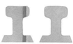
The earliest of these in general use were the so-called cast iron fishbelly rails from their shape. Rails made from cast iron were brittle and broke easily. They could only be made in short lengths which would soon become uneven. John Birkinshaw's 1820 patent,[10] as rolling techniques improved, introduced wrought iron in longer lengths, replaced cast iron and contributed significantly to the explosive growth of railroads in the period 1825-40. The cross-section varied widely from one line to another, but were of three basic types as shown in the diagram. The parallel cross-section which developed in later years was referred to as Bullhead.
Meanwhile, in May 1831, the first flanged T rail (also called T-section) arrived in America from Britain and was laid into the Pennsylvania Railroad by Camden and Amboy Railroad. They were also used by Charles Vignoles in Britain.
The first steel rails were made in 1857 by Robert Forester Mushet, who laid them at Derby station in England.[11] Steel is a much stronger material, which steadily replaced iron for use on railway rail and allowed much longer lengths of rails to be rolled.
The American Railway Engineering Association (AREA) and the American Society for Testing Materials (ASTM) specified carbon, manganese, silicon and phosphorus content for steel rails. Tensile strength increases with carbon content, while ductility decreases. AREA and ASTM specified 0.55 to 0.77 percent carbon in 70-to-90-pound-per-yard (34.7 to 44.6 kg/m) rail, 0.67 to 0.80 percent in rail weights from 90 to 120 lb/yd (44.6 to 59.5 kg/m), and 0.69 to 0.82 percent for heavier rails. Manganese increases strength and resistance to abrasion. AREA and ASTM specified 0.6 to 0.9 percent manganese in 70 to 90 pound rail and 0.7 to 1 percent in heavier rails. Silicon is preferentially oxidised by oxygen and is added to reduce the formation of weakening metal oxides in the rail rolling and casting procedures.[12] AREA and ASTM specified 0.1 to 0.23 percent silicon. Phosphorus and sulfur are impurities causing brittle rail with reduced impact-resistance. AREA and ASTM specified maximum phosphorus concentration of 0.04 percent.[13]
The use of welded rather than jointed track began in around the 1940s and had become widespread by the 1960s.
Types
Strap rail
The earliest rails were simply lengths of timber. To resist wear a thin iron strap was laid on top of the timber rail. This saved money as wood was cheaper than metal. The system had the flaw that every so often the passage of the wheels on the train would cause the strap to break away from the timber. The problem was first reported by Richard Trevithick in 1802. The use of strap rails in the United States (for instance on the Albany and Schenectady Railroad c1837) led to passengers being threatened by "snake-heads" when the straps curled up and penetrated the carriages.[7]
Flanged rail
Flanged rail was an early type of rail and had an 'L' cross section in which the flange kept an unflanged wheel on the track. The flanged rail has seen a minor revival in the 1950s, as guide bars, with the Paris Métro (Rubber-tyred metro or French Métro sur pneus) and more recently as the Guided bus. In the Cambridgeshire Guided Busway the rail is a 350 mm (14 in) thick concrete beam with a 180 mm (7.1 in) lip to form the flange. The buses run on normal road wheels with side mounted guidewheels to run against the flanges. Buses are steered normally when off the busway, analogous to the 18th-century wagons which could be manoeuvered around pitheads before joining the track for the longer haul.
Baulk rail
Baulk road used a lightweight form of bridge rail. The rail was continuously supported by a baulk of timber running longitudinally. Because of the continuous support the rail did not need to behave as a girder and so could be lighter. The baulk road was pioneered by Isambard Kingdom Brunel on the Great Western Railway which was built to a gauge of 7 ft (2,134 mm). The length of convention sleepers would therefore have to be 50% longer and hence more expensive.
Barlow rail

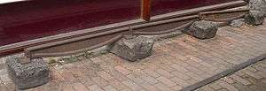
Barlow rail was invented by William Henry Barlow in 1849. It was designed to be laid straight onto the ballast, but the lack of sleepers meant that it was difficult to keep it in gauge.
Flat bottomed rail

Flat bottomed rail is the dominant rail profile in worldwide use.
Flanged T rail (also called T-section) is the name for flat bottomed rail used in North-America. Iron-strapped wooden rails were used on all American railways until 1831. Col. Robert L. Stevens, the President of the Camden and Amboy Railroad, conceived the idea that an all-iron rail would be better suited for building a railroad. There were no steel mills in America capable of rolling long lengths, so he sailed to England which was the only place where his flanged T rail (also called T-section) could be rolled. Railways in England had been using rolled rail of other cross-sections which the ironmasters had produced.
In May 1831, the first 500 rails, each 15 feet (4.6 m) long and weighing 36 pounds per yard (17.9 kg/m), reached Philadelphia and were placed in the track, marking the first use of the flanged T rail. Afterwards, the flanged T rail became employed by all railroads in the United States.
Col. Stevens also invented the hooked spike for attaching the rail to the crosstie (or sleeper). At the present time, the screw spike is being used widely in place of the hooked spike.

Vignoles rail is the popular name of the flat-bottomed rail, recognising engineer Charles Vignoles who introduced it to Britain. Charles Vignoles observed that wear was occurring with wrought iron rails and cast iron chairs upon stone blocks, the most common system at that time. In 1836 he recommended flat-bottomed rail to the London and Croydon Railway for which he was consulting engineer. His original rail had a smaller cross-section to the Stevens rail, with a wider base than modern rail, fastened with screws through the base. Other lines which adopted it were the Hull and Selby, the Newcastle and North Shields, and the Manchester, Bolton and Bury Canal Navigation and Railway Company.[14]
When it became possible to preserve wooden sleepers with mercuric chloride (a process called Kyanising) and creosote, they gave a much quieter ride than stone blocks and it was possible to fasten the rails directly using clips or rail spikes. Their use spread worldwide and acquired Vignoles' name.
The joint where the ends of two rails are connected to each other is the weakest part of a rail line. The earliest iron rails were joined by a simple fishplate or bar of metal bolted through the web of the rail. Stronger methods of joining two rails together have been developed. When sufficient metal is put into the rail joint, the joint is almost as strong as the rest of the rail length. The noise generated by trains passing over the rail joints, described as "the clickity clack of the railroad track", can be eliminated by welding the rail sections together. Continuously welded rail has a uniform top profile even at the joints.
Double-headed rail
In late 1830s England, railway lines had a vast range of different patterns. One of the earliest lines to use double-headed rail was the London and Birmingham Railway, which had offered a prize for the best design. This rail was supported by chairs and the head and foot of the rail had the same profile. The supposed advantage was that, when the head became worn, the rail could be turned over and re-used. In practice, this form of recycling was not very successful as the chair caused dents in the lower surface, and double-headed rail evolved into bullhead rail in which the head was more substantial than the foot.
Bullhead rail
Bullhead rail was the standard for the British railway system from the mid-19th until the mid-20th century. For example, in 1954 bullhead rail was used for 449 miles (723 km) of new track and flat-bottom for 923 miles (1,485 km).[15] One of the first British Standards, BS 9, was for bullhead rail - it was originally published in 1905, and revised in 1924. Rails manufactured to the 1905 standard were referred to as "O.B.S." (Original), and those manufactured to the 1924 standard as "R.B.S." (Revised).[16]
Bullhead rail is similar to double-headed rail except that the profile of the head of the rail is not the same as that of the foot. Bullhead rail evolved from double-headed rail but, because it did not have a symmetrical profile, it was never possible to flip it over and use the foot as the head. Therefore, because the rail no longer had the originally-perceived benefit of reusability, it was a very expensive method of laying track. Heavy cast iron chairs were needed to support the rail, which was secured in the chairs by wooden (later steel) wedges or "keys" which required regular attention.
Bullhead rail has now been almost completely replaced by flat-bottom rail on British railways, although it survives on the national rail system in some sidings or branch lines. The London Underground continued to use bullhead rail after it had been phased out elsewhere in Britain, but in the last few years has there been a concerted effort to convert its track to flat-bottom rail., however the process of replacing track in tunnels is a slow process due to the impossibility of using heavy plant and machinery.[17]
Tangential turnouts


For turnouts (BrE: points), the tips of the switch blades have to be planed down to fit snugly against the fixed or stock rail. The left-hand diagram shows this: on the left is the dotted outline of the rail, with the part remaining after planing-shown shown by a solid line in red. On the right is shown how the two rails fit together when the turnout is closed. The resulting thin pieces of steel are weak, and so old-style turnouts used to make a relatively sudden and sharp angle against the stock rail. With a sudden change in direction, trains were given a jolt and had to proceed slowly.
The right-hand diagram shows a how a tangential turnout is made. A lower, more squat profile rail is used to make the switch blades. On the left is the profile of this squat switch rail. The centre diagram shows how the switch rail has to be planed, and on the right it is shown fitting against the stock rail. Note that a thicker base is used to raise the tops level with each other.
The tangential switch rail has less steel planed away, and the mid part of the switch "scallops" into the web of the stock rail for greater strength. The higher baseplate also supports the switch rail better. This makes a stronger switch which can be curved, reducing the jolt to the train and allowing higher speeds. However tangential turnouts still lack a smooth transition where the switch blade contacts the main rail, so there is still some jolt as the train passes over. It's a much smaller jolt than with the old-style turnouts.
The weight of the two types of rail is about the same.
Grooved rail


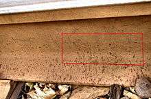
Where a rail is laid in a Road surface (pavement) or within grassed surfaces, there has to be accommodation for the flange. This is provided by a slot called the flangeway. The rail is then known as grooved rail, groove rail, or girder rail. The flangeway has the railhead on one side and the guard on the other. The guard carries no weight, but may act as a checkrail.
Grooved rail was invented in 1852 by Alphonse Loubat, a French inventor who developed improvements in tram and rail equipment, and helped develop tram lines in New York City and Paris. The invention of grooved rail enabled tramways to be laid without causing a nuisance to other road users, except unsuspecting cyclists, who could get their wheels caught in the groove. The grooves may become filled with gravel and dirt (particularly if infrequently used or after a period of idleness) and need clearing from time to time, this being done by a "scrubber" tram. Failure to clear the grooves can lead to a bumpy ride for the passengers, damage to either wheel or rail and possibly derailing.
Girder guard rail
The traditional form of grooved rail is the girder guard section illustrated to the right. This rail is a modified form of flanged rail and requires a special mounting for weight transfer and gauge stabilisation. If the weight is carried by the roadway subsurface, steel ties are needed at regular intervals to maintain the gauge. Installing these means that the whole surface needs to be excavated and reinstated.
Block rail
Block rail is a lower profile form of girder guard rail with the web is eliminated. In profile it is more like a solid form of bridge rail with a flangeway and guard added. Simply removing the web and combining the head section directly with the foot section would result in a weak rail, so additional thickness is required in the combined section.[18]
LR55 rail

LR55 rail is a special rail section, promoted by Tram Power of the UK, designed for use in embedded tramway track installations. The rail itself is like a lop-sided "V". It is a top-suspended rail: the load is transmitted by the rail head, rather than through a web to the rail foot. Slots are cut in the roadway and precast concrete troughs laid in the slots. A polyurethane mastic provides a resilient cushion between the rail and the concrete, minimising transmitted noise, and providing insulation against leakage currents.[19] Since the load is spread across a wider base, it requires less depth for a sub-base than conventional tramway track avoiding the need to disturb existing underground utility services. The installation and maintenance time, and hence cost, is thus greatly reduced. Gauge is maintained by the pavement in which it is installed; there is no need for separate gauging bars between the rails.[20][21] LR55 has been tested in parts of the Sheffield Supertram network.[22]
The same rail has been tested to 80 t (79 long tons; 88 short tons) axle loadings for mainline use, and can be used in tunnels and other locations where the loading gauge is restricted. Replacing flat bottom girder rails on sleepers and ballast with LR55 in tunnels can increase the head room by a minimum of 300 mm (12 in), without the need to excavate the tunnel invert. A method statement to undertake this transformation allows contractors to proceed on an incremental basis without closing the tunnel to rail traffic. Temporary transition rails link flat bottom and LR55 rails, until the conversion is completed.[23] The extra loading gauge can then be used to install overhead electrification, or to move larger rail vehicles. These can include double deck passenger trains and freight trains with high cube (9 ft 6 in or 2.90 m) maritime containers.[24]
Rail lengths
Rails should be made as long as possible since joints between raillengths are a source of weakness. As manufacturing processes have improved, rail lengths have increased. Long rails are flexible, and there is no problem going around curves.[25]
- (In order of date then length)
- 1825 15 feet (4.6 m) Stockton and Darlington Railway 5.6 lb/yd (2.8 kg/m) - See: S&DR
- 1830 15 feet (4.6 m) Liverpool and Manchester Railway 35 lb/yd (17.4 kg/m) fish-belly rails
- 1850 39 feet (11.9 m) United States (to suit 40-foot or 12-metre gondola wagons)
- 1895 60 feet (18.3 m) London and North Western Railway (UK) (four times 15 ft and two times 30 ft)
- 2003 216 metres (709 ft)(Railtrack (UK) Rail Delivery Train)[26]
- 2010 853 metres (2,799 ft) Bhilai Steel Plant
Welding of rails into longer lengths was first introduced around 1893. Welding can be done in a central depot, or in the field.
- 1895 Hans Goldschmidt
- 1935 Charles Cadwell, non-ferrous Thermit welding
Conical or Cylindrical Wheels
It has long been recognised that conical wheels and rails that are sloped by the same amount follow curves better than cylindrical wheels and vertical rails. A few railways such as Queensland Railways for a long time had cylindrical wheels until much heavier traffic required a change.[27] Cylindrical wheel treads have to "skid" on track curves so increase both drag and rail and wheel wear. On very straight track a cylindrical wheel tread rolls more freely and does not "hunt." The gauge is narrowed slightly and the flange fillets keep the flanges from rubbing the rails. United States practice is a 1 in 20 cone when new. As the tread wears it approaches an unevenly cylindrical tread, at which time the wheel is trued on a wheel lathe or replaced.
Manufacturers
Rails are made from high quality steel and not in huge quantities compared with other forms of steel, and so the number of manufacturers in any one country tends to be limited.
- British Steel, (UK & France)[28]
- Arrium, Whyalla, South Australia formerly OneSteel before 2012.
- EVRAZ, Pueblo, CO (United States)
- ArcelorMittal Steelton (United States)
- ArcelorMittal Ostrava, (Czech Republic)
- ArcelorMittal Gijón, (Spain)[29]
- ArcelorMittal Huta Katowice, (Poland)
- ArcelorMittal Huta Kościuszko - former Huta Królewska, (Poland)
- ArcelorMittal Rodange, (Luxembourg)
- Steel Dynamics (United States)
- Nippon Steel & Sumitomo Metal (Japan)
- JFE Steel (Japan)
- EVRAZ, Russia
- Kardemir, (Turkey)
- Steel Authority of India, (India)
- Metinvest (Ukraine)
- BHP (Australia) - former parent of Arrium and One Steel
- One Steel (Australia)
- Voestalpine (Austria)
- AFERPI - ex Lucchini (Italy)
Defunct manufacturers
- Bethlehem Steel (United States)
- Algoma Steel Company (Canada)
- Sydney Steel Corporation (Canada)
- Dowlais Ironworks (Wales, UK)
- Călărași steel works (Romania)
- Barrow Steel Works (England UK)
Standards
- EN 13674-1 - Railway applications - Track - Rail - Part 1: Vignole railway rails 46 kg/m and above
See also
References
- ↑ Rail profile : definition razorbackrailway.com
- ↑ "message in the mailing list '1520 mm' on Р75 rails".
- ↑ Raymond, William G., The Elements of Railroad Engineering, 5th Edition, John Wiley and Sons, 1937
- ↑ Urquhart, Leonard Church, Civil Engineering Handbook, 4th Edition, McGraw-Hill Book Company, 1959
- ↑ D.D. Hagarty (February 1999). "A Short History of Railway Track in Australia - 1 New South Wales". Australian Railway Historical Society Bulletin: 55–67.
- ↑ M. J. T. Lewis, Early Wooden railways (Routledge, London 1970).
- 1 2 Bianculli, Anthony J., Trains and Technology: The American Railroad in the Nineteenth Century, University of Delaware Press, 2002, Chapter 5, "From Strap Iron to High Iron". ISBN 0-87413-802-7
- ↑ "What was a Railroad?". (Includes illustration of a length of strap rail.). Past Tracks. Retrieved 1 February 2011.
- ↑ Bianculli, Anthony J. (2003). Trains and Technology: The American Railroad in the Nineteenth Century - Volume 3: Track and Structures (illustrated ed.). University of Delaware Press. pp. 85–8. ISBN 0-87413-802-7. – This section describes strap rails, their uses and problems in considerable detail.
- ↑ Michael Longridge (1821). Specification of John Birkinshaw's Patent, for an Improvement in the Construction of Malleable Iron Rails, to be used in Rail roads; with Remarks on the comparative Merits of Cast Metal and Malleable Iron Railways. Newcastle: E. Walker.
- ↑ Marshall, John. The Guinness Book of Rail Facts & Feats (1979) ISBN 0-900424-56-7
- ↑ Hay, William W., Railroad engineering, Volume 1, Chapter 24 "Rail", pp.484-485 google books link
- ↑ Abbett, Robert W., American Civil Engineering Practice, Volume I, John Wiley and Sons, 1956
- ↑ Ransom, P.J.G., (1990) The Victorian Railway and How it Evolved, London: Heinemann Ltd.
- ↑ Cooke, B.W.C., ed. (June 1954). "B.R. Track Renewal Programme". The Railway Magazine. Vol. 100 no. 638. Westminster: Tothill Press. p. 433.
- ↑ "Handbook For Permanent Way Staff". Rail Brands. 1958. Retrieved 13 September 2010.
- ↑ "London Underground Track and Traction Current". The Tubeprune. Retrieved 2013-03-22.
- ↑ Grooved or girder rail
- ↑ "The LR55 Track System" Accessed 17-07-2009]
- ↑ "Tram Tracks – LR55 – the next generation of tramway track" Accessed 17-07-2009
- ↑ Trampower - LR55 Track Accessed 17-07-2009
- ↑ "LR55 Field Test, Sheffield Accessed 17-07-2009
- ↑ "LR55-80lb conversion rail" Accessed 17-07-2009
- ↑ "Increasing tunnel loading gauge without lowering the invert", Railway Engineering 2001 Conference, 1 May 2001, Lesley L., Mohammad F.& Al Nageim H.
- ↑ http://www.flickr.com/photos/mr_sam/12384672903/
- ↑ http://vgcgroup.co.uk/project/rail-delivery-framework/
- ↑ http://search.informit.com.au/documentSummary;dn=636110412996855;res=IELENG
- ↑ "British Steel brand revived". Railway Gazette. Retrieved 2016-07-29.
- ↑ "ArcelorMittal manufactures rails that are used all over the world". ArcelorMittal. Retrieved 2012-11-26.
- ↑ http://www.msm.cam.ac.uk/phase-trans/parliament.html
External links
- British Steel rail, Vignoles rail, grooved rail, and special rail (Switch and crossing rail, conductor rail and check rail)
- British Steel crane rail, Crane rails
- ThyssenKrupp handbook, Vignoles rail
- ThyssenKrupp handbook, Light Vignoles rail
- ThyssenKrupp grooved rail
- LR55 Track System Full details
- Table of North American tee rail (flat bottom) sections
- ArcelorMittal Crane Rails
- Track components and materials
- Grooved or girder rail
- Wirth Girder Rail
- MRT Track & Services Co., Inc / Krupp, T and girder rails, scroll down.