EPROM
| Computer memory types |
|---|
| Volatile |
| RAM |
| In development |
| Historical |
|
| Non-volatile |
| ROM |
| NVRAM |
| Early stage NVRAM |
| Mechanical |
| In development |
| Historical |
|
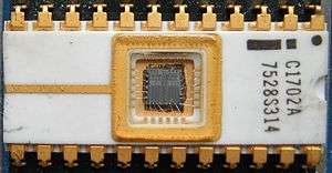
An EPROM (rarely EROM), or erasable programmable read-only memory, is a type of memory chip that retains its data when its power supply is switched off. Computer memory that can retrieve stored data after a power supply has been turned off and back on is called non-volatile. It is an array of floating-gate transistors individually programmed by an electronic device that supplies higher voltages than those normally used in digital circuits. Once programmed, an EPROM can be erased by exposing it to strong ultraviolet light source (such as from a mercury-vapor light). EPROMs are easily recognizable by the transparent fused quartz window in the top of the package, through which the silicon chip is visible, and which permits exposure to ultraviolet light during erasing.
Operation
Development of the EPROM memory cell started with investigation of faulty integrated circuits where the gate connections of transistors had broken. Stored charge on these isolated gates changed their properties. The EPROM was invented by Dov Frohman of Intel in 1971, who was awarded US patent 3660819[1] in 1972.
Each storage location of an EPROM consists of a single field-effect transistor. Each field-effect transistor consists of a channel in the semiconductor body of the device. Source and drain contacts are made to regions at the end of the channel. An insulating layer of oxide is grown over the channel, then a conductive (silicon or aluminum) gate electrode is deposited, and a further thick layer of oxide is deposited over the gate electrode. The floating gate electrode has no connections to other parts of the integrated circuit and is completely insulated by the surrounding layers of oxide. A control gate electrode is deposited and further oxide covers it.[2]
To retrieve data from the EPROM, the address represented by the values at the address pins of the EPROM is decoded and used to connect one word (usually an 8-bit byte) of storage to the output buffer amplifiers. Each bit of the word is a 1 or 0, depending on the storage transistor being switched on or off, conducting or non-conducting.
The switching state of the field-effect transistor is controlled by the voltage on the control gate of the transistor. Presence of a voltage on this gate creates a conductive channel in the transistor, switching it on. In effect, the stored charge on the floating gate allows the threshold voltage of the transistor to be programmed.
Storing data in the memory requires selecting a given address and applying a higher voltage to the transistors. This creates an avalanche discharge of electrons, which have enough energy to pass through the insulating oxide layer and accumulate on the gate electrode. When the high voltage is removed, the electrons are trapped on the electrode.[3] Because of the high insulation value of the silicon oxide surrounding the gate, the stored charge cannot readily leak away and the data can be retained for decades.
The programming process is not electrically reversible. To erase the data stored in the array of transistors, ultraviolet light is directed onto the die. Photons of the UV light cause ionization within the silicon oxide, which allow the stored charge on the floating gate to dissipate. Since the whole memory array is exposed, all the memory is erased at the same time. The process takes several minutes for UV lamps of convenient sizes; sunlight would erase a chip in weeks, and indoor fluorescent lighting over several years.[4] Generally the EPROMs must be removed from equipment to be erased, since it is not usually practical to build in a UV lamp to erase parts in-circuit. The Electrically Erasable Programmable Read-Only Memory (EEPROM) was developed to provide an electrical erase function and has now mostly displaced ultraviolet-erased parts.
Details
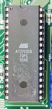
As the quartz window is expensive to make, OTP (one-time programmable) chips were introduced; here, the die is mounted in an opaque package so it cannot be erased after programming – this also eliminates the need to test the erase function, further reducing cost. OTP versions of both EPROMs and EPROM-based microcontrollers are manufactured. However, OTP EPROM (whether separate or part of a larger chip) is being increasingly replaced by EEPROM for small sizes, where the cell cost isn't too important, and flash for larger sizes.
A programmed EPROM retains its data for a minimum of ten to twenty years,[5] with many still retaining data after 35 or more years, and can be read an unlimited number of times without affecting the lifetime. The erasing window must be kept covered with an opaque label to prevent accidental erasure by the UV found in sunlight or camera flashes. Old PC BIOS chips were often EPROMs, and the erasing window was often covered with an adhesive label containing the BIOS publisher's name, the BIOS revision, and a copyright notice. Often this label was foil-backed to ensure its opacity to UV.
Erasure of the EPROM begins to occur with wavelengths shorter than 400 nm. Exposure time for sunlight of one week or three years for room fluorescent lighting may cause erasure. The recommended erasure procedure is exposure to UV light at 253.7 nm of at least 15 W-sec/cm² for 20 to 30 minutes, with the lamp at a distance of about 2.5 cm.
Erasure can also be accomplished with X-rays:
Erasure, however, has to be accomplished by non-electrical methods, since the gate electrode is not accessible electrically. Shining ultraviolet light on any part of an unpackaged device causes a photocurrent to flow from the floating gate back to the silicon substrate, thereby discharging the gate to its initial, uncharged condition (photoelectric effect). This method of erasure allows complete testing and correction of a complex memory array before the package is finally sealed. Once the package is sealed, information can still be erased by exposing it to X radiation in excess of 5*104 rads,[lower-alpha 1] a dose which is easily attained with commercial X-ray generators.[6]
In other words, to erase your EPROM, you would first have to X-ray it and then put it in an oven at about 600 degrees Celsius (to anneal semiconductor alterations caused by the X-rays). The effects of this process on the reliability of the part would have required extensive testing so they decided on the window instead.[7]
EPROMs had a limited but large number of erase cycles; the silicon dioxide around the gates would accumulate damage from each cycle, making the chip unreliable after several thousand cycles. EPROM programming is slow compared to other forms of memory. Because higher-density parts have little exposed oxide between the layers of interconnects and gate, ultraviolet erasing becomes less practical for very large memories. Even dust inside the package can prevent some cells from being erased.[8]
Application
For large volumes of parts (thousands of pieces or more), mask-programmed ROMs are the lowest cost devices to produce. However, these require many weeks lead time to make, since the artwork for an IC mask layer must be altered to store data on the ROMs. Initially, it was thought that the EPROM would be too expensive for mass production use and that it would be confined to development only. It was soon found that small-volume production was economical with EPROM parts, particularly when the advantage of rapid upgrades of firmware was considered.
Some microcontrollers, from before the era of EEPROMs and flash memory, use an on-chip EPROM to store their program. Such microcontrollers include some versions of the Intel 8048, the Freescale 68HC11, and the "C" versions of the PIC microcontroller. Like EPROM chips, such microcontrollers came in windowed (expensive) versions that were useful for debugging and program development. The same chip came in (somewhat cheaper) opaque OTP packages for production. Leaving the die of such a chip exposed to light can also change behavior in unexpected ways when moving from a windowed part used for development to a non-windowed part for production.
EPROM sizes and types
EPROMs come in several sizes both in physical packaging as well and storage capacity. While parts of the same type number from different manufacturers are compatible as long as they're only being read, there are subtle differences in the programming process.
Most EPROMS could be identified by the programmer through "signature mode" by forcing 12 V on pin A9 and reading out two bytes of data. However, as this was not universal, programmer software also would allow manual setting of the manufacturer and device type of the chip to ensure proper programming.[9]
| EPROM Type | Year | Size — bits | Size — bytes | Length (hex) | Last address (hex) |
|---|---|---|---|---|---|
| 1702, 1702A | 1971 | 2 Kbit | 256 | 100 | FF |
| 2704 | 1975 | 4 Kbit | 512 | 200 | 1FF |
| 2708 | 1975 | 8 Kbit | 1 KB | 400 | 3FF |
| 2716, 27C16, TMS2716, 2516 | 1977 | 16 Kbit | 2 KB | 800 | 7FF |
| 2732, 27C32, 2532 | 1979 | 32 Kbit | 4 KB | 1000 | FFF |
| 2764, 27C64, 2564 | 64 Kbit | 8 KB | 2000 | 1FFF | |
| 27128, 27C128 | 128 Kbit | 16 KB | 4000 | 3FFF | |
| 27256, 27C256 | 256 Kbit | 32 KB | 8000 | 7FFF | |
| 27512, 27C512 | 512 Kbit | 64 KB | 10000 | FFFF | |
| 27C010, 27C100 | 1 Mbit | 128 KB | 20000 | 1FFFF | |
| 27C020 | 2 Mbit | 256 KB | 40000 | 3FFFF | |
| 27C040, 27C400, 27C4001 | 4 Mbit | 512 KB | 80000 | 7FFFF | |
| 27C080 | 8 Mbit | 1 MB | 100000 | FFFFF | |
| 27C160 | 16 Mbit | 2 MB | 200000 | 1FFFFF | |
| 27C320, 27C322 | 32 Mbit | 4 MB | 400000 | 3FFFFF |
Gallery
.jpg) A 32 KB (256 Kbit) EPROM
A 32 KB (256 Kbit) EPROM This 8749 Microcontroller stores its program in internal EPROM
 NEC 02716, 16 KBit EPROM
See also
- Programmable read-only memory
- EEPROM
- Flash memory
- Intel HEX - File format
- SREC - File format
- Programmer (hardware)
Notes
References
- ↑ EPROM patent, Google.
- ↑ Sah 1991, p. 639.
- ↑ Oklobdzija, Vojin G. (2008). Digital Design and Fabrication. CRC Press. pp. 5–17. ISBN 0-8493-8602-0.
- ↑ Ayers, John E (2004), Digital integrated circuits: analysis and design, CRC Press, p. 591, ISBN 0-8493-1951-X.
- ↑ Horowitz, Paul; Hill, Winfield (1989), The Art of Electronics (2nd ed.), Cambridge: Cambridge University Press, p. 817, ISBN 0-521-37095-7.
- ↑ Frohman, Dov (May 10, 1971), Electronics Magazine (article).
- ↑ Margolin, J (May 8, 2009). "EPROM"..
- ↑ Sah 1991, p. 640.
- ↑ U.S. International Trade Commission, ed. (October 1998). Certain EPROM, EEPROM, Flash Memory and Flash Microcontroller Semiconductor Devices and Products Containing Same, Inv. 337-TA-395. Diane Publishing. pp. 51–72. ISBN 1-4289-5721-9. The details of SEEQ's Silicon Signature method of a device programmer reading an EPROM's ID.
Bibliography
- Sah, Chih-Tang (1991), Fundamentals of solid-state electronics, World Scientific, ISBN 981-02-0637-2
External links
| Wikimedia Commons has media related to EPROM. |
- Detailed information about EPROM types and EPROM programming
- Video of the Intel 1702 EPROM
- 1976 Intel Data Book, includes 1702, 2704, 2708 datasheets