Heterodyne

Heterodyning is a radio signal processing technique invented in 1901 by Canadian inventor-engineer Reginald Fessenden that creates new frequencies by combining or mixing two frequencies.[1][2][3] Heterodyning is used to shift one frequency range into another, new one, and is also involved in the processes of modulation and demodulation.[2][4] The two frequencies are combined in a nonlinear signal-processing device such as a vacuum tube, transistor, or diode, usually called a mixer.[2] In the most common application, two signals at frequencies f1 and f2 are mixed, creating two new signals, one at the sum f1 + f2 of the two frequencies, and the other at the difference f1 − f2.[3] These new frequencies are called heterodynes. Typically only one of the new frequencies is desired, and the other signal is filtered out of the output of the mixer. Heterodynes are related to the phenomenon of "beats" in acoustics.
A major application of the heterodyne process is in the superheterodyne radio receiver circuit, which is used in virtually all modern radio receivers.
History
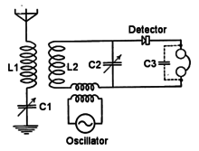
In 1901, Reginald Fessenden demonstrated a direct-conversion heterodyne receiver or beat receiver as a method of making continuous wave radiotelegraphy signals audible. Fessenden's receiver did not see much application because of its local oscillator's stability problem. While complex isochronous electromechanical oscillators existed, a stable yet inexpensive local oscillator was not available until Lee de Forest invented the triode vacuum tube oscillator.[5] In a 1905 patent, Fessenden stated the frequency stability of his local oscillator was one part per thousand.[6]
Early spark gap radio transmitters sent information exclusively by means of radio telegraphy. In radio telegraphy, the characters of text messages are translated into the short duration dots and long duration dashes of Morse code that are broadcast as bursts of radio waves. The heterodyne detector was not needed to hear the signals produced by these spark gap transmitters. The transmitted damped wave signals were amplitude modulated at an audio frequency by the spark. A simple detector produced an audible buzzing sound in the radiotelegraph operator's headphones that could be transcribed back into alpha-numeric characters.
With the development of the arc converter radio transmitter in 1904, continuous wave (CW) modulation began to be used for radiotelegraphy. CW Morse code signals are not amplitude modulated, they simply consist of pulses of sinusoidal carrier frequency, so in an AM receiver a cw signal produces no sound. The direct-conversion detector was invented to make continuous wave radio-frequency signals audible.[7]
The "heterodyne" or "beat" receiver has a local beat frequency oscillator (BFO) that produces a radio signal adjusted to be close in frequency to the incoming signal being received. When the two signals are mixed, a "beat" frequency equal to the difference between the two frequencies is created. By adjusting the local oscillator frequency correctly, the beat frequency is in the audio range, and can be heard as a tone in the receiver's earphones whenever the transmitter signal is present. Thus the Morse code "dots" and "dashes" are audible as beeping sounds. This technique is still used in radio telegraphy, the local oscillator now being called the beat frequency oscillator or BFO. Fessenden coined the word heterodyne from the Greek roots hetero- "different", and dyn- "power" (cf. δύναμις or dunamis).[8]
Superheterodyne receiver
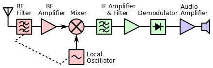
The most important and widely used application of the heterodyne technique is in the superheterodyne receiver (superhet), invented by U.S. engineer Edwin Howard Armstrong in 1918. In this circuit, the incoming radio frequency signal from the antenna is mixed with a signal from a local oscillator and converted by the heterodyne technique to a somewhat lower fixed frequency signal called the intermediate frequency (IF). This IF signal is amplified and filtered, before being applied to a detector that extracts the audio signal, which is sent to the loudspeaker.
The advantage of this technique is that the different frequencies of the different stations received are all converted to the same IF before amplification and filtering. The complicated amplifier and bandpass filter stages, which in previous receivers had to be made tunable to work at the different station frequencies, in the superheterodyne can be built to work at one fixed frequency, the IF, simplifying their design. Another advantage is that the IF is at a considerably lower frequency than the RF frequency of the incoming radio signal.
The superior superheterodyne system replaced the earlier TRF and regenerative receiver designs, and since the 1930s almost all commercial radio receivers have been superheterodynes.
Applications
Heterodyning, also called frequency conversion, is used very widely in communications engineering to generate new frequencies and move information from one frequency channel to another. Besides its use in the superheterodyne circuit found in almost all radio and television receivers, it is used in radio transmitters, modems, satellite communications and set-top boxes, radar, radio telescopes, telemetry systems, cell phones, cable television converter boxes and headends, microwave relays, metal detectors, atomic clocks, and military electronic countermeasures (jamming) systems.
Up and down converters
In large scale telecommunication networks such as telephone network trunks, microwave relay networks, cable television systems, and communication satellite links, large bandwidth capacity links are shared by many individual communication channels by using heterodyning to move the frequency of the individual signals up to different frequencies, which share the channel. This is called frequency division multiplexing (FDM).
For example, a coaxial cable used by a cable television system can carry 500 television channels at the same time because each one is given a different frequency, so they don't interfere with one another. At the cable source or headend, electronic upconverters convert each incoming television channel to a new, higher frequency. They do this by mixing the television signal frequency, fCH with a local oscillator at a much higher frequency fLO, creating a heterodyne at the sum fCH + fLO, which is added to the cable. At the consumer's home, the cable set top box has a downconverter that mixes the incoming signal at frequency fCH + fLO with the same local oscillator frequency fLO creating the difference heterodyne, converting the television channel back to its original frequency: (fCH + fLO) − fLO = fCH. Each channel is moved to a different higher frequency. The original lower basic frequency of the signal is called the baseband, while the higher channel it is moved to is called the passband.
Analog videotape recording
Many analog videotape systems rely on a downconverted color subcarrier to record color information in their limited bandwidth. These systems are referred to as "heterodyne systems" or "color-under systems". For instance, for NTSC video systems, the VHS (and S-VHS) recording system converts the color subcarrier from the NTSC standard 3.58 MHz to ~629 kHz.[9] PAL VHS color subcarrier is similarly downconverted (but from 4.43 MHz). The now-obsolete 3/4" U-matic systems use a heterodyned ~688 kHz subcarrier for NTSC recordings (as does Sony's Betamax, which is at its basis a 1/2″ consumer version of U-matic), while PAL U-matic decks came in two mutually incompatible varieties, with different subcarrier frequencies, known as Hi-Band and Low-Band. Other videotape formats with heterodyne color systems include Video-8 and Hi8.[10]
The heterodyne system in these cases is used to convert quadrature phase-encoded and amplitude modulated sine waves from the broadcast frequencies to frequencies recordable in less than 1 MHz bandwidth. On playback, the recorded color information is heterodyned back to the standard subcarrier frequencies for display on televisions and for interchange with other standard video equipment.
Some U-matic (3/4″) decks feature 7-pin mini-DIN connectors to allow dubbing of tapes without a heterodyne up-conversion and down-conversion, as do some industrial VHS, S-VHS, and Hi8 recorders.
Music synthesis
The theremin, an electronic musical instrument, traditionally uses the heterodyne principle to produce a variable audio frequency in response to the movement of the musician's hands in the vicinity of one or more antennas, which act as capacitor plates. The output of a fixed radio frequency oscillator is mixed with that of an oscillator whose frequency is affected by the variable capacitance between the antenna and the thereminist as that person moves her or his hand near the pitch control antenna. The difference between the two oscillator frequencies produces a tone in the audio range.
The ring modulator is a type of heterodyne incorporated into some synthesizers or used as a stand-alone audio effect.
Optical heterodyning
Optical heterodyne detection (an area of active research) is an extension of the heterodyning technique to higher (visible) frequencies. This technique could greatly improve optical modulators, increasing the density of information carried by optical fibers. It is also being applied in the creation of more accurate atomic clocks based on directly measuring the frequency of a laser beam. See NIST subtopic 9.07.9-4.R for a description of research on one system to do this.[11][12]
Since optical frequencies are far beyond the manipulation capacity of any feasible electronic circuit, all photon detectors are inherently energy detectors not oscillating electric field detectors. However, since energy detection is inherently "square-law" detection, it intrinsically mixes any optical frequencies present on the detector. Thus, sensitive detection of specific optical frequencies necessitates optical heterodyne detection, in which two different (close-by) wavelengths of light illuminate the detector so that the oscillating electrical output corresponds to the difference between their frequencies. This allows extremely narrow band detection (much narrower than any possible color filter can achieve) as well as precision measurements of phase and frequency of a light signal relative to a reference light source, as in a laser Doppler vibrometer.
This phase sensitive detection has been applied for Doppler measurements of wind speed, and imaging through dense media. The high sensitivity against background light is especially useful for lidar.
In optical Kerr effect (OKE) spectroscopy, optical heterodyning of the OKE signal and a small part of the probe signal produces a mixed signal consisting of probe, heterodyne OKE-probe and homodyne OKE signal. The probe and homodyne OKE signals can be filtered out, leaving the heterodyne signal for detection.
Mathematical principle
Heterodyning is based on the trigonometric identity:

The product on the left hand side represents the multiplication ("mixing") of a sine wave with another sine wave. The right hand side shows that the resulting signal is the difference of two sinusoidal terms, one at the sum of the two original frequencies, and one at the difference, which can be considered to be separate signals.
Using this trigonometric identity, the result of multiplying two sine wave signals, and can be calculated:


![\sin(2\pi f_{1}t)\sin(2\pi f_{2}t)={\frac {1}{2}}\cos[2\pi (f_{1}-f_{2})t]-{\frac {1}{2}}\cos[2\pi (f_{1}+f_{2})t]\,](../I/m/e21c16bec0a362c9195ef213d24b47ff64b1af38.svg)
The result is the sum of two sinusoidal signals, one at the sum f1 + f2 and one at the difference f1 − f2 of the original frequencies
Mixer
The two signals combine in a device called a mixer. As seen in the previous section, an ideal mixer would be a device that multiplies the two signals. Some widely used mixer circuits, such as the Gilbert cell, operate in this way, but they are limited to lower frequencies. However, any nonlinear electronic component also multiplies signals applied to it, producing heterodyne frequencies in its output—so a variety of nonlinear components serve as mixers. A nonlinear component is one in which the output current or voltage is a nonlinear function of its input. Most circuit elements in communications circuits are designed to be linear. This means they obey the superposition principle; if F(v) is the output of a linear element with an input of v:

So if two sine wave signals at frequencies f1 and f2 are applied to a linear device, the output is simply the sum of the outputs when the two signals are applied separately with no product terms. Thus, the function F must be nonlinear to create heterodynes (mixer products). A perfect multiplier only produces mixer products at the sum and difference frequencies (f1 ± f2), but more general nonlinear functions produce higher order mixer products: n⋅f1 + m⋅f2 for integers n and m. Some mixer designs, such as double-balanced mixers, suppress some high order undesired products, while other designs, such as harmonic mixers exploit high order differences.
Examples of nonlinear components that are used as mixers are vacuum tubes and transistors biased near cutoff (class C), and diodes. Ferromagnetic core inductors driven into saturation can also be used at lower frequencies. In nonlinear optics, crystals that have nonlinear characteristics are used to mix laser light beams to create heterodynes at optical frequencies.
Output of a mixer
To demonstrate mathematically how a nonlinear component can multiply signals and generate heterodyne frequencies, the nonlinear function F can be expanded in a power series (MacLaurin series):

To simplify the math, the higher order terms above α2 are indicated by an ellipsis (". . .") and only the first terms are shown. Applying the two sine waves at frequencies ω1 = 2πf1 and ω2 = 2πf2 to this device:


It can be seen that the second term above contains a product of the two sine waves. Simplifying with trigonometric identities:
![{\displaystyle {\begin{aligned}v_{\text{out}}={}&\alpha _{1}(A_{1}\sin \omega _{1}t+A_{2}\sin \omega _{2}t)\\&{}+\alpha _{2}\left({\frac {A_{1}^{2}}{2}}[1-\cos 2\omega _{1}t]+A_{1}A_{2}[\cos(\omega _{1}t-\omega _{2}t)-\cos(\omega _{1}t+\omega _{2}t)]+{\frac {A_{2}^{2}}{2}}[1-\cos 2\omega _{2}t]\right)+\cdots \end{aligned}}}](../I/m/6859bceb95ea2209e85fc7e377005cd5d3f7ae27.svg)

So the output contains sinusoidal terms with frequencies at the sum ω1 + ω2 and difference ω1 − ω2 of the two original frequencies. It also contains terms at the original frequencies and at multiples of the original frequencies 2ω1, 2ω2, 3ω1, 3ω2, etc.; the latter are called harmonics, as well as more complicated terms at frequencies of Mω1 + Nω2, called intermodulation products. These unwanted frequencies, along with the unwanted heterodyne frequency, must be filtered out of the mixer output by an electronic filter to leave the desired heterodyne.
See also
- Beat receptor
- Direct-conversion receiver – heterodyne conversion of a signal directly to baseband instead of to an intermediate frequency
- Heterodyne detection
- Optical heterodyne detection
- Beat (acoustics)
- Edwin Howard Armstrong
- Electroencephalography
- Homodyne
- Superheterodyne receiver
- Transverter
- Intermodulation – a problem with strong higher-order terms produced in some non-linear mixers
Notes
- ↑ Christopher E. Cooper (January 2001). Physics. Fitzroy Dearborn Publishers. pp. 25–. ISBN 978-1-57958-358-3. Retrieved 27 July 2013.
- 1 2 Graf, Rudolf F. (1999). Modern dictionary of electronics, 7th Ed. USA: Newnes. p. 344. ISBN 0-7506-9866-7.
- ↑ Horowitz, Paul; Winfield Hill (1989). The Art of Electronics, 2nd Ed. London: Cambridge University Press. pp. 885, 897. ISBN 0-521-37095-7.
- ↑ Nahin 2001, p. 91, stating "Fessenden's circuit was ahead of its time, however, as there simply was no technology available then with which to build the required local oscillator with the necessary frequency stability." Figure 7.10 shows a simplified 1907 heterodyne detector.
- ↑ Fessenden 1905, p. 4
- ↑ Ashley, Charles Grinnell; Heyward, Charles Brian (1912). Wireless Telegraphy and Wireless Telephony. Chicago: American School of Correspondence. pp. 103/15–104/16.
- ↑ Tapan K. Sarkar, History of wireless, page 372
- ↑ Videotape formats using 1⁄2-inch-wide (13 mm) tape ; Retrieved 2007-01-01
- ↑ Poynton, Charles. Digital Video and HDTV: Algorithms and Interfaces San Francisco: Morgan Kaufmann Publishers, 2003 PP 582, 583 ISBN 1-55860-792-7
- ↑ Contract Details: Robust Nanopopous Ceramic Microsensor Platform
- ↑ Contract Details: High Pulsed Power Varactor Multipliers for Imaging
References
- US 1050441, Fessenden, Reginald A., "Electric Signaling Apparatus", published July 27, 1905, issued January 14, 1913
- Glinsky, Albert (2000), Theremin: Ether Music and Espionage, Urbana, IL: University of Illinois Press, ISBN 0-252-02582-2
- Nahin, Paul J. (2001), The Science of Radio with Matlab and Electronics Workbench Demonstrations (second ed.), New York: Springer-Verlag, AIP Press, ISBN 0-387-95150-4
External links
- Hogan, John V. L. (April 1921), "The Heterodyne Receiver", Electric Journal, 18: 116
- US 706740, Fessenden, Reginald A., "Wireless Signaling", published September 28, 1901, issued August 12, 1902
- US 1050728, Fessenden, Reginald A., "Method of Signaling", published August 21, 1906, issued January 14, 1913