Deflection (engineering)
In engineering, deflection is the degree to which a structural element is displaced under a load. It may refer to an angle or a distance.
The deflection distance of a member under a load is directly related to the slope of the deflected shape of the member under that load and can be calculated by integrating the function that mathematically describes the slope of the member under that load. Deflection can be calculated by standard formula (will only give the deflection of common beam configurations and load cases at discrete locations), or by methods such as virtual work, direct integration, Castigliano's method, Macaulay's method or the direct stiffness method, amongst others. The deflection of beam elements is usually calculated on the basis of the Euler–Bernoulli beam equation while that of a plate or shell element is calculated using plate or shell theory.
An example of the use of deflection in this context is in building construction. Architects and engineers select materials for various applications. The beams used for frame work are selected on the basis of deflection, amongst other factors.
Beam deflection for various loads and supports
Beams can vary greatly in their geometry and composition. For instance, a beam may be straight or curved. It may be of constant cross section, or it may taper. It may be made entirely of the same material (homogeneous), or it may be composed of different materials (composite). Some of these things make analysis difficult, but many engineering applications involve cases that are not so complicated. Analysis is simplified if:
- -The beam is originally straight, and any taper is slight
- -The beam experiences only linear elastic deformation
- -The beam is slender (its length to height ratio is greater than 10)
- -Only small deflections are considered (max deflection less than 1/10 the span).
In this case, the equation governing the beam's deflection () can be approximated as:


where the second derivative of its deflected shape with respect to is interpreted as its curvature, is the Young's modulus, is the area moment of inertia of the cross-section, and is the internal bending moment in the beam.


If, in addition, the beam is not tapered and is homogeneous, and is acted upon by a distributed load , the above expression can be written as:


This equation can be solved for a variety of loading and boundary conditions. A number of simple examples are shown below. The formulas expressed are approximations developed for long, slender, homogeneous, prismatic beams with small deflections, and linear elastic properties. Under these restrictions, the approximations should give results within 5% of the actual deflection.
Cantilever beams
Cantilever beams have one end fixed, so that the slope and deflection at that end must be zero.
End-loaded cantilever beams

The elastic deflection and angle of deflection (in radians) at the free end in the example image: A (weightless) cantilever beam, with an end load, can be calculated (at the free end B) using:[1]


where
- = Force acting on the tip of the beam
- = Length of the beam (span)
- = Modulus of elasticity
- = Area moment of inertia of the beam's cross section


Note that if the span doubles, the deflection increases eightfold. The deflection at any point, , along the span of an end loaded cantilevered beam can be calculated using:[1]


Note that at (the end of the beam), the and equations are identical to the and equations above.


Uniformly-loaded cantilever beams
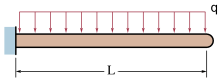
The deflection, at the free end B, of a cantilevered beam under a uniform load is given by:[1]


where
- = Uniform load on the beam (force per unit length)
- = Length of the beam
- = Modulus of elasticity
- = Area moment of inertia of cross section
The deflection at any point, , along the span of a uniformly loaded cantilevered beam can be calculated using:[1]


Simply-supported beams
Simply-supported beams have supports under their ends which allow rotation, but not deflection.
Center-loaded simple beams

The elastic deflection (at the midpoint C) of a beam, loaded at its center, supported by two simple supports is given by:[1]

where
- = Force acting on the center of the beam
- = Length of the beam between the supports
- = Modulus of elasticity
- = Area moment of inertia of cross section
The deflection at any point, , along the span of a center loaded simply supported beam can be calculated using:[1]

for

Off-center-loaded simple beams

The maximum elastic deflection on a beam supported by two simple supports, loaded at a distance from the closest support, is given by:[1]


where
- = Force acting on the beam
- = Length of the beam between the supports
- = Modulus of elasticity
- = Area moment of inertia of cross section
- = Distance from the load to the closest support (i.e. )

This maximum deflection occurs at a distance from the closest support and is given by:[1]


Uniformly-loaded simple beams
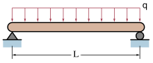
The elastic deflection (at the midpoint C) on a beam supported by two simple supports, under a uniform load (as pictured) is given by:[1]

where
- = Uniform load on the beam (force per unit length)
- = Length of the beam
- = Modulus of elasticity
- = Area moment of inertia of cross section
The deflection at any point, , along the span of a uniformly loaded simply supported beam can be calculated using:[1]

—–
Units
The formulas supplied above require the use of a consistent set of units. Most calculations will be made in SI or US customary units, although there are many other systems of units.
International system (SI)
- Force: newtons ()

Length: meters ()

- Modulus of elasticity:
- Moment of inertia:


US customary units (US)
- Force: pounds force ()
- Length: inches ()
- Modulus of elasticity:
- Moment of inertia:


Others
Other units may be used as well, as long as they are self-consistent. For example, sometimes the kilogram force () unit is used to measure loads. In such a case, the modulus of elasticity must be converted to .


Structural deflection
Building codes determine the maximum deflection, usually as a fraction of the span e.g. 1/400 or 1/600. Either the strength limit state (allowable stress) or the serviceability limit state (deflection considerations amongst others) may govern the minimum dimensions of the member required.
The deflection must be considered for the purpose of the structure. When designing a steel frame to hold a glazed panel, one allows only minimal deflection to prevent fracture of the glass.
The deflected shape of a beam can be represented by the moment diagram, integrated (twice, rotated and translated to enforce support conditions).
See also
References
External links
- Deflection & stress of beams Calculators
- Deflection of beams
- Online Calculator for Deflection and slope of beams
- Beam Deflections
- Beam Deflections (Tabulated)