Clos network
In the field of telecommunications, a Clos network is a kind of multistage circuit switching network, first formalized by Charles Clos in 1952,[1] which represents a theoretical idealization of practical multi-stage telephone switching systems. Clos networks are required when the physical circuit switching needs to exceed the capacity of the largest feasible single crossbar switch. The key advantage of Clos networks is that the number of crosspoints (which make up each crossbar switch) required can be far fewer than would be the case if the entire switching system were implemented with one large crossbar switch. When the Clos network was first devised, the number of crosspoints was a reasonable approximate indication of the total cost of the switching system. While this was important for electromechanical crossbars, it became less relevant with the advent of VLSI, wherein the interconnects often could be implemented either directly in silicon, or within a relatively small cluster of boards. However, the advent of complex data centers, with huge interconnect structures, each based on optical fiber links, means that they are again important.[2]
Clos networks have three stages: the ingress stage, middle stage, and the egress stage. Each stage is made up of a number of crossbar switches (see diagram below), often just called crossbars. Each call entering an ingress crossbar switch can be routed through any of the available middle stage crossbar switches, to the relevant egress crossbar switch. A middle stage crossbar is available for a particular new call if both the link connecting the ingress switch to the middle stage switch, and the link connecting the middle stage switch to the egress switch, are free.

Clos networks are defined by three integers n, m, and r. n represents the number of sources which feed into each of r ingress stage crossbar switches. Each ingress stage crossbar switch has m outlets, and there are m middle stage crossbar switches. There is exactly one connection between each ingress stage switch and each middle stage switch. There are r egress stage switches, each with m inputs and n outputs. Each middle stage switch is connected exactly once to each egress stage switch. Thus, the ingress stage has r switches, each of which has n inputs and m outputs. The middle stage has m switches, each of which has r inputs and r outputs. The egress stage has r switches, each of which has m inputs and n outputs.
Blocking characteristics
The relative values of m and n define the blocking characteristics of the Clos network.
Strict-sense nonblocking Clos networks (m ≥ 2n−1): the original 1953 Clos result
If m ≥ 2n−1, the Clos network is strict-sense nonblocking, meaning that an unused input on an ingress switch can always be connected to an unused output on an egress switch, without having to re-arrange existing calls. This is the result which formed the basis of Clos's classic 1953 paper. Assume that there is a free terminal on the input of an ingress switch, and this has to be connected to a free terminal on a particular egress switch. In the worst case, n−1 other calls are active on the ingress switch in question, and n−1 other calls are active on the egress switch in question. Assume, also in the worst case, that each of these calls passes through a different middle-stage switch. Hence in the worst case, 2n−2 of the middle stage switches are unable to carry the new call. Therefore, to ensure strict-sense nonblocking operation, another middle stage switch is required, making a total of 2n−1.
Rearrangeably nonblocking Clos networks (m ≥ n)
If m ≥ n, the Clos network is rearrangeably nonblocking, meaning that an unused input on an ingress switch can always be connected to an unused output on an egress switch, but for this to take place, existing calls may have to be rearranged by assigning them to different centre stage switches in the Clos network.[3] To prove this, it is sufficient to consider m = n, with the Clos network fully utilised; that is, r×n calls in progress. The proof shows how any permutation of these r×n input terminals onto r×n output terminals may be broken down into smaller permutations which may each be implemented by the individual crossbar switches in a Clos network with m = n.
The proof uses Hall's marriage theorem[4] which is given this name because it is often explained as follows. Suppose there are r boys and r girls. The theorem states that if every subset of k boys (for each k such that 0 ≤ k ≤ r) between them know k or more girls, then each boy can be paired off with a girl that he knows. It is obvious that this is a necessary condition for pairing to take place; what is surprising is that it is sufficient.
In the context of a Clos network, each boy represents an ingress switch, and each girl represents an egress switch. A boy is said to know a girl if the corresponding ingress and egress switches carry the same call. Each set of k boys must know at least k girls because k ingress switches are carrying k×n calls and these cannot be carried by less than k egress switches. Hence each ingress switch can be paired off with an egress switch that carries the same call, via a one-to-one mapping. These r calls can be carried by one middle-stage switch. If this middle-stage switch is now removed from the Clos network, m is reduced by 1, and we are left with a smaller Clos network. The process then repeats itself until m = 1, and every call is assigned to a middle-stage switch.
Blocking probabilities: the Lee and Jacobaeus approximations
Real telephone switching systems are rarely strict-sense nonblocking for reasons of cost, and they have a small probability of blocking, which may be evaluated by the Lee or Jacobaeus approximations,[5] assuming no rearrangements of existing calls. Here, the potential number of other active calls on each ingress or egress switch is u = n−1.
In the Lee approximation, it is assumed that each internal link between stages is already occupied by a call with a certain probability p, and that this is completely independent between different links. This overestimates the blocking probability, particularly for small r. The probability that a given internal link is busy is p = uq/m, where q is the probability that an ingress or egress link is busy. Conversely, the probability that a link is free is 1−p. The probability that the path connecting an ingress switch to an egress switch via a particular middle stage switch is free is the probability that both links are free, (1−p)2. Hence the probability of it being unavailable is 1−(1−p)2 = 2p−p2. The probability of blocking, or the probability that no such path is free, is then [1−(1−p)2]m.
The Jacobaeus approximation is more accurate, and to see how it is derived, assume that some particular mapping of calls entering the Clos network (input calls) already exists onto middle stage switches. This reflects the fact that only the relative configurations of ingress switch and egress switches is of relevance. There are i input calls entering via the same ingress switch as the free input terminal to be connected, and there are j calls leaving the Clos network (output calls) via the same egress switch as the free output terminal to be connected. Hence 0 ≤ i ≤ u, and 0 ≤ j ≤ u.
Let A be the number of ways of assigning the j output calls to the m middle stage switches. Let B be the number of these assignments which result in blocking. This is the number of cases in which the remaining m−j middle stage switches coincide with m−j of the i input calls, which is the number of subsets containing m−j of these calls. Then the probability of blocking is:

If fi is the probability that i other calls are already active on the ingress switch, and gj is the probability that j other calls are already active on the egress switch, the overall blocking probability is:

This may be evaluated with fi and gj each being denoted by a binomial distribution. After considerable algebraic manipulation, this may be written as:

Clos networks with more than three stages
Clos networks may also be generalised to any odd number of stages. By replacing each centre stage crossbar switch with a 3-stage Clos network, Clos networks of five stages may be constructed. By applying the same process repeatedly, 7, 9, 11,... stages are possible.
Beneš network (m = n = 2)
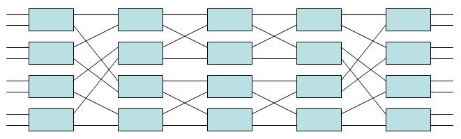
A rearrangeably nonblocking network of this type with m = n = 2 is generally called a Beneš network, even though it was discussed and analyzed by others before Václav E. Beneš. The number of inputs and outputs is N = r×n = 2r. Such networks have 2 log2N − 1 stages, each containing N/2 2×2 crossbar switches, and use a total of N log2N − N/2 2×2 crossbar switches. For example, an 8×8 Benes network (i.e. with N = 8) is shown below; it has 2 log28 − 1 = 5 stages, each containing N/2 = 4 2×2 crossbar switches, and it uses a total of N log2N − N/2 = 20 2×2 crossbar switches. The central three stages consist of two smaller 4×4 Benes networks, while in the center stage, each 2×2 crossbar switch may itself be regarded as a 2×2 Benes network. This example therefore highlights the recursive construction of this type of network.
See also
- Crossbar switch Describes the switching element of a Clos network.
- Nonblocking minimal spanning switch Describes the switching algorithm of a Clos network.
- Banyan switch An alternative way to connect networks.
- Fat tree An alternative way to connect networks.
- Omega network An alternative way to connect networks.
References
- ↑ Clos, Charles (Mar 1953). "A study of non-blocking switching networks" (PDF). Bell System Technical Journal. 32 (2): 406–424. doi:10.1002/j.1538-7305.1953.tb01433.x. ISSN 0005-8580. Retrieved 22 March 2011.
- ↑ http://www.networkworld.com/article/2226122/cisco-subnet/clos-networks--what-s-old-is-new-again.html
- ↑ Beneš, Václav E. (11 September 1965). Mathematical Theory of Connecting Networks and Telephone Traffic. Academic Press. ISBN 0-12-087550-0.
- ↑ Hall, Philip (January 1935). "On Representatives of Subsets" (PDF). Journal of the London Mathematical Society. s1. 10 (1): 26–30. doi:10.1112/jlms/s1-10.37.26. Retrieved 2015-06-18.
- ↑ Hui, Joseph Y. (1990). Switching and Traffic Theory for Integrated Broadband Networks. Kluwer Academic Publishers. ISBN 0-7923-9061-X.