Chimney (locomotive)

The chimney (smokestack or stack in American and Canadian English) is the part of a steam locomotive through which smoke leaves the boiler. Steam locomotive exhaust systems typically vent cylinder exhaust through the chimney to enhance draught through the boiler. Chimneys are designed to carry exhaust steam and smoke clear of the driver's line of sight while remaining short enough to clear overhead structures. Some chimneys included features to avoid dispersing sparks.
Function
The chimney was usually located above the smokebox at the leading end of the locomotive, furthest away from the driver's cab and firebox. The earliest locomotive chimneys were typically tall enough to sustain temperature-induced density difference draught through a fire-tube boiler while the locomotive was stationary; but following the example of Richard Trevithick's first locomotive in 1804, most designs diverted steam cylinder exhaust upward through the chimney to create a vacuum in the smokebox and accelerate airflow through the firebox while the locomotive was in motion.[1]
Locomotives with high chimneys and low footplates had the additional advantage of keeping smoke and condensing steam above the engine driver's field of vision. Grade limitations of railways through hilly terrain required tunnels and overhead bridges imposing a loading gauge limiting the height of chimneys. Increasing the velocity of steam exhaust tended to both accelerate airflow through the firebox and lift the smoke higher above the end of the chimney. By the 1830s steam exhaust was directed through a contracted nozzle called a blastpipe to achieve desired velocity through the chimney. Pressure drop through the blastpipe nozzle was subtracted from the boiler pressure available to the steam pistons. Robert Stephenson estimated some locomotives lost half their power through blastpipe back pressure.[2]
As boiler design improved heat transfer efficiency, blast pipe diameters increased to reduce back pressure; and blastpipes became shorter to discharge below the chimney rather than within it. Ross Winans placed conical "petticoat pipes" above blastpipes about 1848[2] to form the convergent portion of a venturi tube with the chimney forming the divergent portion.[3] Improved understanding of compressible flow encouraged more sophisticated blastpipe and venturi chimney designs. George Jackson Churchward, working at Swindon on the Great Western Railway, formulated a simple equation for calculating the ideal dimensions for chimneys which worked well for the early years of the 20th century, but soon become outdated as engine powers increased. André Chapelon in France continued to work on chimney dimensions, and studied them in conjunction with blastpipe dimensions as a complete Steam locomotive exhaust system, such as his famous Kylchap system as fitted to many locomotive classes worldwide. Even after the end of commercial steam in most of the developed world, the Argentinean engineer Livio Dante Porta continued to work on developing steam locomotive exhaust systems including refining equations to give better chimney dimensions.
Spark arrestors
Locomotives built in Great Britain, where coke was the most common fuel, often used chimneys of cast iron, as they lasted longer than chimneys fabricated from sheet metal. Early North American locomotives often used wood fuel; and large numbers of glowing embers were carried through the boiler and out of the chimney by high velocity exhaust steam.[4] Spark arrestors became a common feature of wood-burning locomotive chimneys to reduce the number of fires started by escaped embers. The difficulty of casting complex spark arrestors encouraged fabrication of sheet metal chimneys for wood-burning locomotives.[5]
Early spark arrestors were simply iron wire screens installed within the stack. This screen reduced the rate at which smoke and steam could escape from the boiler. Embers caught upon the screen further reduced available space for passing steam and smoke and heat generated by these burning embers rapidly melted the restraining wire screen. Chimney top diameters enlarged to increase screen surface area and reduce smoke velocity through the screen so embers might fall away from the screen into collection hoppers. Baldwin Locomotive Works compiled a diagram illustrating 57 different spark arresting chimney designs in response to an 1857 patent infringement claim.[4]
The most popular design was a bonnet chimney. The bonnet was a funnel-shaped sheet metal cone fitted over a conventional cylindrical chimney. The lower, small-diameter portion of the cone served as a collection hopper for falling embers. The upper portion of the cone concealed an inner cone at the top of the cylindrical chimney which deflected escaping steam, smoke and embers outward against the inner walls of the outer cone. The heavier embers were expected to fall into the hopper below while the lighter steam and smoke passed upward through a wire screen over the upper, large-diameter end of the outer cone. Deflection of the embers typically lengthened screen life to three or four weeks. Some of these chimneys had provisions dropping collected embers into a portion of the smokebox called the subtreasury. Sophisticated designs like the Radley & Hunter included various centrifugal separation baffles into the bonnet. As coal replaced wood fuel, the bonnet was reduced into a simple diamond stack housing the inner deflecting cone (with or without the upper wire screen) but without any collection hopper.[4]
Aesthetics
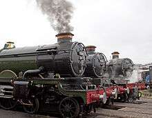
The bonnet chimney became one of the most distinctive features contributing, with the large rectangular oil headlamp, an air of frontal grandeur to 19th-century American locomotives.[4] Many designers or railway companies had their own distinctive style, such as the William Adams' "Stovepipe" chimney on the 19th century LSWR, or the copper-capped chimneys on the Great Western Railway.
As locomotive boilers grew larger, the space available for chimneys was reduced, as they still had to fit within the same loading gauge. This reduced their effectiveness at keeping the exhaust gases away from the driver's line of sight, and as a result locomotives had to be fitted with devices such as smoke deflectors.
Notes
Sources
- Phillips, Lance (1965). Yonder Comes the Train. Cranberry, New Jersey: A.S. Barnes and Company. ISBN 0-498-06303-8.
- Sears, Francis Weston; Zemansky, Mark W. (1964). University Physics (Third ed.). Reading, Massachusetts: Addison-Wesley Publishing Company.
- White, John H., Jr. (1979). A History of the American Locomotive (Dover ed.). New York: Dover Publications. ISBN 0-486-23818-0.
| Wikimedia Commons has media related to Steam locomotive chimneys. |