Chain Home

Chain Home, or CH for short, was the codename for the ring of coastal Early Warning radar stations built by the Royal Air Force (RAF) before and during the Second World War to detect and track aircraft.[1] The term also referred to the radar equipment itself, until it was given the official name Air Ministry Experimental Station Type 1 (AMES Type 1) in 1940. Chain Home was the first operational radar system in the world.
In 1934, Nikola Tesla claimed to have invented a radio-based death ray, followed by a report in a German newspaper suggesting they had built one. The Tizard Committee formed to consider the possibility, and asked Robert Watt, a well known expert on radio physics, to comment. Watt's assistant, Arnold Wilkins, calculated that a death ray was impossible, but suggested that long-range detection was a possibility. A demonstration was arranged by placing a receiver near a BBC shortwave transmitter, and flying an aircraft around the area; the signal was clearly affected. Watt and his team rapidly developed a prototype system using commercial shortwave radio equipment. Although this equipment was less than ideal for the role, Watt was adamant about delivering a good enough system immediately, as opposed to a better system never. Major development was completed in under a year, and the first five stations covering the approaches to London were operational by 1937.
Early experiments demonstrated that the reports from independent stations were difficult to coordinate, and relaying that information to the pilots in fighter aircraft even more so. Hugh Dowding identified the problem arising from too many reports of the same targets from different stations. He implemented the world's first integrated air defence network, the Dowding system, to handle the flow of information.[lower-alpha 1] Dozens of CH stations and a complete ground network were ready by the time World War II began in 1939. CH systems would often detect larger formations of aircraft over France, allowing commanders to marshal their entire force directly in the path of the raid. This had the effect of multiplying the effectiveness of the RAF to the point that it was as if they had three times as many fighters. With such high efficiency, it was no longer the case that "the bomber will always get through". The system proved decisive during the Battle of Britain in 1940.
The Chain Home network was continually expanded, with over forty stations operational by the war's end. CH was not able to detect aircraft at low altitude, and from 1939 was normally partnered with the Chain Home Low system, or AMES Type 2, which could detect aircraft flying at minimum altitude level of 500 ft (150 m). This was further refined by the addition of Chain Home Extra Low, or AMES Type 14, which gave cover down to 50 ft (15 m) but at short ranges of only approximately 30 miles (50 km). In 1942 the AMES Type 7 radar began to take over the job of tracking of targets once detected, and CH turned its attention entirely to the early warning role. Late in the war, when the threat of Luftwaffe bombing had ended, the CH systems were used to detect V2 missile launches. After the war, they were reactivated as part of the ROTOR system to watch for Soviet bombers, before being replaced by newer systems in the later 1950s. Today only a few of the original sites remain intact in any fashion.
Development
Prior experiments
From the earliest days of radio technology, signals had been used for navigation systems using the radio direction finding (RDF) technique. RDF can determine the bearing to a radio transmitter, and several such measurements can be combined to produce a radio fix, indicating the location of the receiver.[2] Given some basic changes to the broadcast signal, it was possible for the receiver to determine its location using a single station, and the UK pioneered one such service in the form of the Orfordness Beacon.[3]
Through the early period, it was also widely known that objects positioned between the transmitter and receiver would affect the received signal. This led to the possibility of determining the location of objects using a combination of RDF and other techniques. Such a system saw patents issued to Christian Hülsmeyer in 1904,[4] and widespread experimentation with the basic concept had been carried out continuously since then. These systems revealed only the bearing to the target, and due to low power had relatively short range, so they were useful only for short-range warning in fog or bad weather.[4]
The observation that moving objects caused a noticeable pattern to develop in the received signal due to the Doppler effect caused a second wave of experiments during the 1930s. Teams in the UK, US,[5] Japan,[6] Germany[7] and others had all discovered this effect and put at least some small amount of effort into developing them. However, these systems did not provide ranging information and were therefore of limited use in practical terms.[5]
Radio research in the UK
In the UK, Robert Watt[lower-alpha 2] had developed the most advanced form of basic RDF during the 1920s. Combining a directional Adcock antenna array with a cathode ray tube, he created a system later known as huff-duff, that allowed the almost instantaneous determination of the bearing to a signal. This, along with much of his other work at the National Physical Laboratory's (NPL) Radio Research Section (RRS) at Ditton Park in Slough, made Watt a well-known expert in the field of radio technology.[8]
During this same period, Edward Appleton of King's College, Cambridge University, was carrying out experiments that would lead to him winning the Nobel Prize in Physics. Using a BBC transmitter set up in 1923 in Bournemouth, and listening for its signal with a receiver at Oxford University, he was able to use changes in wavelength to measure the distance to a reflective layer in the atmosphere then known as the Heaviside layer. After the initial experiments at Oxford, an NPL transmitter at Teddington was used as a source, received by Appleton in an out-station of King's College in the east end of London. Watt, working at another NPL station, learned of these experiments and began receiving the same signals using his team's receivers in Slough. From then on, the two teams interacted regularly, and it was Watt that coined the term ionosphere to describe the multiple atmospheric layers they discovered.[9]
In 1931, Arnold Frederic Wilkins joined Watt's staff in Slough. As the "new boy", he was given a variety of menial tasks to complete. One of these was to select a shortwave receiver for ionospheric studies, a task he took to with undue seriousness. After reading everything available on several units, he selected a model from the General Post Office (GPO) that worked at what was at that time very high frequencies. As part of their tests of this system, in June 1932 the GPO published a report, No. 232 Interference by Aeroplanes. The report recounted the GPO testing team's observation that aircraft flying near the receiver caused the signal to change its intensity, an annoying effect known as fading.[10]
Although it was not clear to anyone involved, the stage was now set for the development of radar. Using Wilkins' knowledge that shortwave signals bounced off aircraft, a BBC transmitter to light up the sky as in Appleton's experiment, and Watt's RDF technique to measure angles, a complete radar could be built. The missing technique was the use of pulses of radio signal to measure range, as opposed to Appleton's method using varying wavelengths. This very concept had been prototyped by W. A. S. Butement and P. E. Pollard of the Signals Experimental Establishment (SEE) in 1931, but ignored by the War Office and little known outside SEE.[11]
Tesla and the death ray
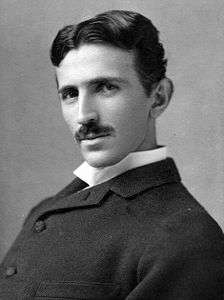
On 11 July 1934, the New York Times published an article by Nikola Tesla claiming he had invented a death ray that could destroy aircraft at a range of 250 miles (400 km). Not long after, a story appeared in German newspapers making similar claims, accompanied by an image of a very large radio antenna. The idea was not entirely absurd; Tesla had noted the ability of high frequency alternating current to warm tissue in 1891, and a German physician had suggested using this for therapeutic uses in 1909, giving it the name diathermy. Such systems were widespread by the 1930s, although they operated at ranges of only a few inches.[12]
Inventors had repeatedly claimed to have built devices that projected this effect over long ranges, but all had proved fraudulent.[lower-alpha 3] The RAF offered a prize to anyone who could demonstrate a working model that could kill a sheep at 100 yards;[13] it went unclaimed.[10] Nevertheless, it remained theoretically possible, and the newspaper story suggested the Germans had cracked it.[10]
This prompted Harry Wimperis to press for the formation of a study group to consider the concept of a death ray, and more broadly, the entire issue of air defence. Lord Londonderry, then Secretary of State for Air, approved the formation of the Committee for the Scientific Survey of Air Defence in November 1934, asking Henry Tizard to chair the group, which thus became better known to history as the Tizard Committee.[14]
When Wimperis went looking for an expert in radio to help judge the death-ray concept, he was naturally directed to Watt. The two met in mid-January 1935,[15] and Watt promised to look into the matter. Watt turned to Wilkins for help, but wanted to keep the underlying question a secret. He asked Wilkins to calculate what sort of radio energy would be needed to raise the temperature of 8 imperial pints (4.5 l) of water at a distance of 5 kilometres (3.1 mi) from 98 to 105 °F (37 to 41 °C). Wilkins immediately surmised this was a question about a death ray, to Watt's bemusement. Wilkins made a number of back-of-the-envelope calculations[16] demonstrating that the amount of energy needed would be impossible given the state of the art in electronics.[17]
Detection and location

According to R. V. Jones, when Wilkins reported the negative results to Watt, Watt then asked, "Well then, if the death ray is not possible, how can we help them?"[18] Wilkins recalled the earlier report from the GPO, and noted that the length of a contemporary's bomber aircraft's wings, about 25 m in span, would make them just right to form a half-wavelength dipole antenna for signals in the range of 50 m wavelength, about 6 MHz. In theory, such a system would give early indication of approaching aircraft. Watt wrote back to Wimperis, saying the death ray was extremely unlikely, but added:
| “ | Attention is being turned to the still difficult, but less unpromising, problem of radio detection and numerical considerations on the method of detection by reflected radio waves will be submitted when required.[17] | ” |
The letter was discussed at the first official meeting of the Tizard Committee on 28 January 1935.[19] The utility of the concept was evident to all attending, but the question remained whether it was actually possible. Albert Rowe and Wimperis both checked the math and it appeared to be correct. They immediately wrote back asking for a more detailed consideration. Watt and Wilkins followed up with 14 February secret memo entitled Detection and Location of Aircraft by Radio Means.[19] In the new memo, Watt and Wilkins first considered various natural emanations from the aircraft, light, heat and radio waves, and demonstrated that these were too easy for the enemy to mask to a level that would be undetectable at range. They concluded that radio waves from their own transmitter would be needed.[17]
Wilkins gave specific calculations for the expected reflectivity of an aircraft and concluded that existing 15 Amp transmitters (about 10 kW) would likely produce a signal detectable at about 10 miles (16 km). The bearing of the signal could be determined using Watt's radio direction finding techniques.[17] They went on to suggest that the output power could be increased as much as ten times if the system operated in pulses instead of continually, and that such a system would have the advantage of allowing range to the targets to be determined by measuring the time delay between transmission and reception on an oscilloscope. The memo concluded with an outline for a complete station using this technique. The design was almost identical to the CH stations that went into service.[17]
Daventry experiment

The letter was seized on by the Committee, who immediately released £4,000 to begin development. They petitioned Hugh Dowding, the Air Member for Supply and Research, to ask the Treasury for another £10,000. Dowding was extremely impressed with the concept, but demanded that a practical demonstration be provided before further funding could be released.[20][21]
Wilkins suggested using the new 10 kW, 49.8 m BBC Borough Hill shortwave station in Daventry as a suitable ad hoc transmitter. The receiver and an oscilloscope were placed in a delivery van the RRS had previously used for measuring radio reception around the countryside. They parked it in a field near Upper Stowe, and connected it to suitable wire antennas stretched across the field on top of wooden poles. On 26 February 1935 a Handley Page Heyford made four passes over the area, producing clearly notable effects on their receiver display on three of the passes.[22]
Observing the test were Watt, Wilkins and several other members of the RRS team, along with Rowe representing the Tizard Committee. Watt was so impressed he later claimed to have exclaimed:[20]
| “ | Britain has become an island again![20] | ” |
Rowe and Dowding were equally impressed, and days later, the Treasury released another £12,300 for further development.[20] A system was to be built at the RRS station, and then moved to Orfordness for over-water testing. Wilikins would develop the receiver based on the GPO units, along with suitable antenna systems. But this left the problem of developing a suitable pulsed transmitter. An engineer familiar with these concepts was needed.[23]
Experimental system
Edward George Bowen joined the team after responding to a newspaper advertisement looking for a radio expert. Bowen had previously worked on ionosphere studies under Appleton, and was thus well acquainted with the basic concepts. Starting with the BBC transmitter electronics, Bowen produced a system that transmitted a 25 kW signal at 6 MHz (50 metre wavelength), sending out 25 μs long pulses 25 times a second.[23]
The team, now consisting of three scientific officers and six assistants, moved the equipment to Orfordness on 15 May 1935.[22] The system showed little success against aircraft, although echoes from the ionosphere as far as 1,000 miles were noted. The group released several reports on these effects as a cover story, claiming that their ionospheric studies had been interfering with the other experiments at the RRS at Slough, and expressing their gratitude that the Air Ministry had granted them access to unused land at Orfordness to continue their efforts.[24]
Bowen tried increasing the power to 100 kW by increasing the voltage to 100,000 V, but this caused arcing between the tubes. This required the transmitter to be redesigned with more room between the components.[24] This did not immediately appear to solve the detection problems. During a visit by the Committee members on 15 June, the system failed to detect an aircraft Watt had secretly asked to fly nearby; Watt later claimed to have seen returns, although no one else did.
Nevertheless, with no changes made, two days later on 17 June the system was turned on and immediately provided returns on a Supermarine Scapa flying boat at a range of 17 miles (27 km). This is widely considered the official birth date of radar in the UK.[25] Improvements to the system continued and the transmitter reached 200 kW. On a 24 July test, the receiver detected a target at 40 miles (64 km) range, and the signal was strong enough they could determine the target was actually three aircraft in close formation.
Planning the chain

In August, Albert Percival Rowe, secretary of the Committee, coined the term "Radio Direction and Finding", deliberately choosing a name that could be confused with "Radio Direction Finding", a term that was already in widespread use.[25] In a 9 September 1935 memo, Watt outlined the progress to date and suggested building a complete network of stations located 20 miles (32 km) apart along the entire east coast. Since the transmitters and receivers were separate, to save development costs he suggested placing a transmitter at every other station. The transmitter signal could be used by a receiver at that site as well as the ones on either side of it. He also asked for a central research station to be set up, "of large size and with ground space for a considerable number of mast and aerial systems".[26]
When the Committee next visited in October 1935, range was up to 80 miles (130 km), and Wilkins was already working on a method for height finding using multiple antennas.[26] In spite of its ad hoc nature and short development time of less than six months, the Orfordness system had already become a useful and practical system. In comparison, the acoustic mirror systems that had been in development for a decade was still limited to only 5 mi (8.0 km) range under most conditions, and was very difficult to use in practice. Work on mirror systems ended, and on 19 December, a £60,000 contract for five[lower-alpha 4] Chain Home stations along the south-east coast was sent out.[26]
The only person not convinced of the utility of RDF was Frederick Lindemann, who strongly supported the use of infrared systems for detection and tracking. Lindemann was a friend and personal advisor to Winston Churchill, who had used his political power to have Lindemann placed on the committee. Numerous observers have noted Lindemann's continual interference, promoting his own ideas over radar. He became increasingly hostile to RDF, but with Churchill's backing the other member's complains were ignored. The other Committee members ultimately solved this problem by dissolving the original Committee and reforming with Appleton in Lindemann's place.[26]
To solve the problem of building a suitable experimental station in the area, Watt suggested a manor house that he noticed on a Sunday drive, some 10 mi (16 km) south of Orfordness. In February and March 1936 the team moved to Bawdsey Manor and established the Air Ministry Experimental Station (AMES). The test system was moved from Orfordness and reconstructed at Bawdsey, and later became an operational site under the name RAF Bawdsey.[27]
Deployment
The system was deliberately developed using existing commercially available technology to speed introduction.[28] The development team could not afford the time to develop and debug new technology. Watt, a pragmatic engineer, believed that "third-best" would do if "second-best" would not be available in time and "best" never available at all.[29]
During the summer of 1936, experiments were carried out at RAF Biggin Hill to examine what effect the presence of radar would have on an air battle.[30] Assuming that RDF would provide them 15 minutes warning, they developed interception techniques that put the fighters in front of the bombers with increasing efficiency. They found that the main problems were finding their own aircraft's location, and ensuring the fighters were at the right altitude.
The lessons learned and techniques of fighter control evolved were applied directly to the creation of the Dowding system that led operations in the Battle of Britain in 1940. By the outbreak of war in September 1939 there were 21 operational Chain Home stations. After the Battle of France in 1940 the network was expanded to cover the west coast and Northern Ireland. The Chain continued to be expanded throughout the war, and by 1940 it stretched from Orkney in the north to Weymouth in the south. This provided radar coverage for the entire European-facing side of the British Isles, able to detect high-flying targets well over France.
By 1937, improvements to the original design were being introduced. A major change was the introduction of systems that allowed the altitude of the targets to be estimated. This system consisted of several sets of antennas separated vertically on the receiver masts, which could be connected to the goniometer in place of the original crossed loops. The operator could select a pair of antennas and then use the goniometer to determine the maximum signal point within a lobe. Other changes included the ability to operate on several frequencies, allowing the radar to change its frequency if the enemy attempted to jam their signals, and work on improved receivers and mobile versions of the equipment.[31]
Industry partners were canvassed in early 1937, and a production network was organized covering many companies. Metropolitan-Vickers took over design and production of the transmitters, AC Cossor did the same for the receivers, the Radio Transmission Equipment Company worked on the goniometers, and the GPO were designed by a joint AMES-GPO group. The Treasury gave approval for full-scale deployment in August, and the first production contacts were sent out for 20 sets in November, a total cost of 380,000.[31] Installation of 15 of these sets were carried out their 1937 and into 1938. In June 1938 a London headquarters was set up to organize the rapidly growing force. This became the Directorate of Communications Development (DCD), with Watt named as the director. Wilkins followed Watt to the DCD, and A. P. Rowe took over AMES at Bawdsey. In August 1938, the first five stations were declared operational and entered service during the Munich crisis, starting full-time operation in September.[32]
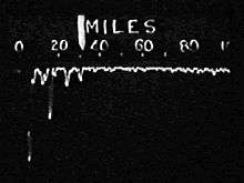
In operation, CH was difficult to use. At any given instant the display indicated the strength of received signals as lines descending vertically down the face of the CRT. Each of these blips indicated the distance to a given object along a single direction, the line of shoot. Using a separate control, known as a radio goniometer, the operated changed the sensitive direction of the receiver antennas while watching the pattern on the display. When a particular blip reached its maximum or minimum value, the range and the angle of the goniometer were read off to a plotter. The plotter then had to turn that range and angle into a location on a modified version of a Ordnance Survey National Grid map. Once that was done, telephone operators had to report those locations up the chain of command, where the data was plotted and then re-sent to other stations. The system as a whole was enormously manpower intensive. Chain Home certainly suffered from glitches and errors in reporting, but skilful operation and acceptance of various limitations (poor low-level cover and a very low frequency data rate) produced an effective system that worked well.[29]
The rapid expansion of the CH necessitated more technical and operational personnel than the UK could provide, and in 1940, a formal request was made by the United Kingdom High Commissioner in Ottawa of the Canadian Government, appealing for men skilled in radio technology for the service of the defence of Great Britain. By the end of 1941, 1,292 trained personnel had enlisted and most were rushed to England to serve as radar mechanics.[33]
Upgrades
Chain Home was the primary radar system for the UK for only a short time. By 1942 many of its duties had been taken over by the far more advanced AMES Type 7 GCI radar systems. Whereas CH scanned an area perhaps 100 degrees wide and required considerable effort to take measurements, the Type 7 scanned the entire 360 degree area around the station, and presented it on a plan position indicator, essentially a real-time two-dimensional map of the airspace around the station. Both fighters and bombers appeared on the display, and could be distinguished using IFF signals. The data from this display could be read directly to the intercepting pilots, without the need for additional operators or control centres.
With the deployment of GCI, CH became the early warning portion of the radar network. To further simplify operations and reduce manpower requirements, the job of plotting the targets became semi-automated. An analog computer of some complexity, known simply as the fruit machine, was fed the bearing and range directly from the operator console, reading the goniometer setting directly, and the range from the setting of a dial that moved a mechanical pointer along the screen until it lay over a selected target. When a button was pushed, the fruit machine read the inputs and calculated the X and Y location of the target, which a single operator could then plot on a map, or relay directly over the telephone.[29]
The original transmitters were constantly upgraded, first from 100 kW of the Orfordness system to 350 kW for the deployed system, and then again to 750 kW to offer greatly increased range. To aid in detection at long range, a slower 12.5 pulse per second rate was added. The four-tower transmitter was later reduced to three towers.
Big Ben
The arrival of the V-2 rocket in September 1944 was initially met with no potential response. The missiles flew too high and too fast to be detected on their approach, leaving no time even for an air raid warning to be sounded. Their supersonic speed meant that the explosions occurred without warning, before the sound of their approach reached the target. The government initially tried to pass them off as explosions in the underground gas mains. However, it was clear this was not the case, and eventually examples of the V-2 falling in its final plunge were captured on film.
In response, several CH stations were re-organized into the "Big Ben" system to report the V-2s during launch. No attempt was made to try to find the location of the launch; the radiogoniometer was simply too slow to use. Instead, each of the stations in the network, Bawdsey, Gt. Bromley, High St, Dunkirk and Swingate (Dover) were left set to their maximum range settings and in the altitude measuring mode. In this mode, the radar had several stacked lobes where they were sensitive to signals. As the missile ascended it would pass through these lobes in turn, causing a series of blips to fade in and out over time. The stations attempted to rapidly measure these ranges and forward them by telephone to a central plotting station.[34]
At the station, these range measurements were plotted as arcs on a chart, or so-called range cuts. The intersections of the arcs defined the approximate area of the launcher. Since the missile approached the target as it climbed, each of these intersections would be closer to the target. Taking several of these in turn, the trajectory of the missile could be determined to some degree of accuracy, and air raid warnings sent to likely areas.[34] RAF Fighter Command was also informed of the launch in an effort to attack the sites, although this met with no success. Similar systems were later used for mortar locating radars like the Green Archer.
Description
Mechanical layout
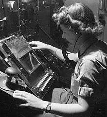
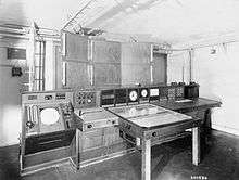
Chain Home radar installations were normally composed of two sites. One compound contained the transmitter towers with associated structures, and a second compound, normally within a few hundred metres distance, contained the receiver masts and receiver equipment block where the operators (principally WAAF, Women's Auxiliary Air Force) worked.[35] The CH system was, by modern terminology, a "bistatic radar", although modern examples normally have their transmitters and receivers far more widely separated.
The transmitter antenna consisted of four steel towers 360 feet (110 m) tall, set out in a line about 180 feet (55 m) apart. Three large platforms were stationed on the tower, at 50, 200 and 350 feet off the ground. A 600 ohm transmission cable was suspended from the top platform to the ground on either side of the platform (only on the inside of the end towers). Between these vertical feed cables were the antennas proper, eight half-wave dipoles strung between the vertical cables and spaced ½ of a wavelength apart. They were fed from alternating sides so the entire array of cables was in-phase, given their ½ wavelength spacing. Located behind each dipole was a passive reflector wire, spaced 0.18 wavelength back.[35]
The resulting curtain array antenna produced a horizontally polarised signal that was directed strongly forward along the perpendicular to the line of the towers. This direction was known as the line of shoot, and was generally aimed out over the water. The broadcast pattern covered an area of about 100 degrees in a roughly fan-shaped area, with a smaller side lobe to the rear, courtesy of the reflectors, and much smaller ones to the sides. When the signal reflected off the ground it underwent a ½ wavelength phase-change, which caused it to interfere with the direct signal. The result was a series of vertically-stacked lobes about 5 degrees wide from 1 degree off the ground to the vertical. The system was later expanded by adding another set of four additional antennas closer to the ground, wired in a similar fashion.[35]
The receiver consisted of an Adcock array consisting of four 240 foot (73 m) tall wooden towers arranged at the corners of a square. Each tower had three sets (originally two) of receiver antennas, one at 45, 95 and 215 feet off the ground. The mean height of the transmitter stack was 215 feet,[35] which is why the topmost antenna was positioned at the same altitude in order to produce a reception pattern that was identical to the transmission. A set of motor-driven mechanical switches allowed the operator to select which antenna was active. The output of the selected antenna on all four towers was sent to a single radiogoniometer system (not Watt's own huff-duff solution). By connecting the antennas together in X-Y pairs the horizontal bearing could be measured, while connecting together the upper and lower antennas allowed the same goniometer to be used to measure the vertical angle.[36]
Two physical layout plans were used, either 'East Coast'[37] or 'West Coast'.[38] West Coast sites replaced the steel lattice towers with simpler guy-stayed masts, although they retained the same wooden towers for reception. East Coast sites had transmitter and receiver blocks protected with earth mounds and blast walls, along with separate reserve transmitter and receivers in small bunkers with attached 120 ft aerial masts. These reserves were in close proximity to the respective transmitter/receiver sites, often in a neighbouring field. West Coast sites relied on site dispersal for protection, duplicating the entire transmitter and receiver buildings.
Transmitter details
Operation began with the Type T.3026 transmitter sending a pulse of radio energy into the transmission antennas from a hut beside the towers. Each station had two T.3026's, one active and one standby. The signal filled space in front of the antenna, floodlighting the entire area. Due to the transmission effects of the multiple stacked antennas, the signal was most strong directly along the line of shoot, and dwindled on either side. An area about 50 degrees to either side of the line was filled with enough energy to make detection practical.[35]
The Type T.3026 transmitter was provided by Metropolitan-Vickers based on a design used for a BBC transmitter at Rugby.[39] A unique feature of the design was the "demountable" tubes, which could be opened for service, and had to be connected to a oil diffusion vacuum pump for continual evacuation while in use. The tubes were able to operate at one of four selected frequencies between 20 and 55 MHz, and switched from one to another in 15 seconds. To produce the short pulses of signal, the transmitter consisted of Hartley oscillators feeding a pair of tetrode amplifier tubes. The tetrodes were switched on and off by a pair of mercury vapour thyratrons connected to a timing circuit, the output of which biased the control and screen grids of the tetrode positively while a bias signal kept it normally turned off.[40]
Stations were arranged so their fan-shaped broadcast patterns slightly overlapped to cover gaps between the stations. To ensure that the stations did not broadcast at the same time, power from the National Grid was used to provide a convenient phase-locked 50 Hz signal that was available across the entire nation. Each station was equipped with a phase-shifting transformer that allowed it to trigger at a specific point on the Grid waveform, selecting a different point for each station to avoid overlap. The output of the transformer was fed to a Dippy oscillator that produced sharp pulses at 25 Hz, phase-locked to the output from the transformer. The locking was "soft", so short-term variations in the phase or frequency of the grid were filtered out.[41] The system of spacing the transmissions out in time was known as "running rabbits".[35]
During times of strong ionospheric reflection, especially at night, it was possible that the receiver would see reflections from the ground after one reflection. To address this problem, the system was later provided with a second pulse repetition frequency at 12.5 pps, which meant that a reflection would have to be from greater than 6,000 miles (9,700 km) before it would be seen during the next reception period.[35]
Receiver details
In addition to triggering the broadcast signal, the output of the transmitter trigger signal was also sent to the receiver hut. Here it fed the input to a time base generator that drove the X-axis deflection plates of the cathode ray tube display. This caused the electron beam in the tube to start moving left-to-right at the instant that the transmission was completed. Due to the slow decay of the pulse, which was rounded and not perfectly square, some of the transmitted signal was received on the display. This signal was so powerful it overwhelmed any reflected signal from targets, which meant that objects closer than about 5 miles (8.0 km) could not be seen on the display. To reduce this period even to this point required the receiver to be hand-tuned, selecting the decoupling capacitors and impedance of the power supplies.[42]
The receiver system, built by A.C. Cossor to a TRE design, was a multiple-stage superheterodyne design. The signal from the selected antennas on the receiver towers were fed through the radiogoniometer and then into a three-stage amplifier, with each stage housed in a metal screen box to avoid interference between the stages. Each stage used a Class B amplifier arrangement of EF8s, special low noise, "aligned-grid" pentodes.[lower-alpha 5] The output of the initial amplifier was then set to the intermediate frequency mixer, which extracted a user-selectable amount of the signal, 500, 200 or 50 kHz as selected by a switch on the console. The first setting allowed most of the signal through, and was used under most circumstances. The other settings were available to block out interference, but did so by also blocking some of the signal which reduced the overall sensitivity of the system.[42]
The output of the mixer was sent to the Y-axis deflection plates in a specially designed high-quality cathode ray tube.[44] For reasons not well explained in the literature, this was arranged to deflect the beam downward with increasing signal.[lower-alpha 6] When combined with the X-axis signal from the time base generator, echoes received from distant objects caused the display to produce blips along the display. By measuring the centre point of the blip against a mechanical scale along the top of the display, the range to the target could be determined. This measurement was later aided by the addition of the calibrator unit or strobe, which caused additional sharp blips to be drawn every 10 miles (16 km) along the display.[45] The markers were fed from the same electronic signals as the time base, so it was always properly calibrated.
Distance and bearing measurement
Determining the actual location in space of a given blip was a complex multi-step process.
First the operator would select a set of receiver antennas using the motorized switch, feeding signals to the receiver system. The antennas were connected together in pairs, forming two directional antennas, sensitive primarily along the X or Y axis, Y being the line of shoot. The operator would then "swing the gonio", or "hunt", back and forth until the selected blip reached its minimum deflection on this display (or maximum, at 90 degrees off). The operator would measure the distance against the scale, and then tell the plotter the range and bearing of the selected target. The operator would then select a different blip on the display and repeat the process. For targets at different altitudes, the operator might have to try different antennas to maximize the signal.[46]
On the receipt of a set of polar coordinates from the radar operator, the plotter's task was to convert these to X and Y locations on a map. They were provided with large maps of their operational area printed on light paper so they could be stored for future reference. A rotating straightedge with the counterpoint at the radar's location on the map was fixed on top, so when the operator called an angle the plotter could quickly rotate to that angle, pick off the range, and plot a point. Plotting altitude was more complex, as it required simple trigonometry. A variety of calculators and aids were used to help in this calculation step. As the plotter worked, the targets would be updated over time, causing a series of marks, or plots, to appear that indicated the targets direction of motion, or track. Track-tellers standing around the map would then relay this information via telephone to the filter room at RAF Bentley Priory, where a dedicated telephone operator relayed that information to plotters on a much larger map. In this way the reports from multiple stations were re-created into a single overall view.[47]
Due to differences in reception patterns between stations, as well as differences in received signals from different directions even at a single station, the reported locations varied from the target's real location by a varying amount. The same target as reported from two different stations could appear in very different locations on the filter room's plot. It was the job of the filter room to recognize these were actually the same plot, and re-combine them into a single track. From then on the tracks were identified by a number, which would be used for all future communications. When first reported the tracks were given an "X" prefix, and then "H" for Hostile or "F" for friendly once identified.[45][lower-alpha 7] This data was then sent down the telephone network to the Group and Section headquarters where the plots were again re-created for local control over the fighters. The data also went sideways to other defence units such as Royal Navy, Army anti-aircraft gun sites and RAF barrage balloon operations. There was also comprehensive liaison with the civil authorities, principally Air Raid Precautions.
Altitude measurement

Due to the arrangement of the receiver antennas, the sensitive area had a number of side lobes that allowed reception at multiple vertical angles. Typically the operator would use the upper set of antennas at 215 feet (66 m), which had the clearest view of the horizon. Due to the half-wave interference from the ground, the main lobe from this antenna was directed at about 2.5 degrees above the horizontal, with its sensitive region extending from about 1 to 3 degrees. At the ground the gain was zero, which allowed aircraft to escape detection by flying at low altitudes. The second lobe extended from about 6 to 12 degrees, and so on. This left a distinct gap in the reception pattern centred at about 5.2 degrees.
This reception pattern provided CH which a relatively accurate way to estimate the altitude of the target. To do this, the motorized switch in the receiver hut was used to disconnect the four receiver masts and instead select the two vertically displaced antennas on one mast. When connected to the radiogoniometer, the output on the display was now effected by the relative signal strength of the two lobes, rather than the relative strengths in X and Y in the horizontal plane. The operator swung the radiogoniometer looking for the peak or minimum reception, as before, and noted the angle.
The number reported by the operator was the line-of-sight range to the target, or slant range, which included components of both the horizontal distance and altitude. To convert this to the real range on the ground, the plotter used basic trigonometry on a right angle triangle; the slant range was the hypotenuse and the open angle was the measurement from the radiogoniometer. The base and opposite sides could then be calculated, revealing the distance and altitude. An important correction was the curvature of the Earth, which became significant at the ranges CH worked at. Once calculated, this allowed the range to be properly plotted, revealing the grid square for the target, which was then reported up the chain.
When the target was first detected at long range, the signal typically did not have enough of a return in the second lobe to perform height finding. This only became possible as the aircraft approached the station. Eventually this problem would recur as the target centred itself in the second lobe, and so forth. Additionally, it was not possible to determine the difference between a signal being compared between the first and second or second and third lobe, which caused some ambiguity at short ranges. However, as the altitude was likely determined long before this, this tended not to be a problem in practice.
Unfortunately this pattern left a set of distinct angles where reception in both lobes was very low. To address this, a second set of receiver antennas were installed at 45 feet (14 m). When the two lower sets of antennas were used, the pattern was shifted upward, providing strong reception in the "gaps", at the cost of diminished long-range reception due to the higher angles.
Raid assessment
Another critical function of the CH operators was to estimate the number and type of aircraft in a raid. A gross level of the overall size could be determined by the strength of the return. But a much more accurate determination could be made by observing the "beat" rate of the composite echoes, the way they grew and diminished over time as they entered into different sections of the antenna reception pattern. To aid this, the operator could reduce the pulse length to 6 microseconds (from 20) with a push-button. This improved the range resolution, spreading the blip out on the display at the cost of lower returned energy.[48]
Raid assessment was largely an acquired skill and continued to improve with operator experience. In measured tests, experimenters found that acquired skill was so great that experienced operators could often pick out targets with returns less than the current signal-to-noise ratio. How this was accomplished was a great mystery at the time - the operators were spotting blips in static that were larger than the signal. It is currently believed this is a form of stochastic resonance.[48]
Fruit machine

Operating a CH station was a manpower-intensive situation, with an operator in the transmitter hut, an operator and assistant in the receiver hut, and as many as six assistants in the receiver hut operating the plotters, calculators and telephone systems. In order to provide 24-hour service, multiple crews were needed, along with a number of service and support personnel. Moreover, this level of staffing was then multiplied by the reporting hierarchy, which required similar numbers of WAAFs at each level of the Dowding system hierarchy. As no small part of the crew was dedicated to calculation and plotting, a great reduction in staffing could be made by using as much automation as possible. This started with the use of various mechanical aids, but these were eventually replaced by the fruit machine, an electromechanical analog computer of some complexity.[45]
The calculations were primarily based on the range and angle information fed from the operator. To automate this step, an electrical repeater was added to the radiogoniometer dial. For range, a new dial was added that moved a mechanical marker to a selected blip on the display. When a particular target was properly selected, the operator pushed a button to activate the fruit machine, which then read these inputs. In addition to the inputs, the fruit machine also had a series of local corrections for both angle and altitude, as measured by calibration flights.These corrections were automatically added to the calculation, eliminating the time-consuming lookup of these numbers from tables.[48] A second button triggered a similar calculation for altitude. The output of the device drove a T-square-like indicator on the chart, allowing the operator to read the calculated location directly.
Detection, jamming and counter-jamming
Early detection
From May to August 1939 the LZ130 Graf Zeppelin II made flights along Britain's North Sea coast to investigate the 100-metre-high radio towers that were being erected from Portsmouth to Scapa Flow. LZ130 performed a series of radiometric tests and took photographs. German sources report the 12 m Chain Home signals were detected and suspected to be radar; however, the chief investigator was not able to prove his suspicions.[49] Other sources are said to report different results.[lower-alpha 8]
During the Battle of France, the Germans observed 12 m pulse signals on the western front without being able to recognize their origin and purpose. In mid-June 1940, the Deutsche Versuchsanstalt für Luftfahrt (DVL, German Aeronautic Research Institute) set up a special group under the direction of Professor von Handel and found out that the signals originated from the installations on the coast of the English Channel.[50] Their suspicions were finally proven in the aftermath of the Battle of Dunkirk, when the British were forced to abandon a mobile Gun Laying radar station in Normandy.
Anti-jamming technologies
The British had been aware that the Germans would determine the purpose of the system and attempt to interfere with it, and had designed in a variety of features and methods in order to address some of these issues even as the first stations were being built. The most obvious of these was CH's ability to operate on different frequencies, which was added to allow the stations to avoid any sort of continuous-broadcast interference on their operating frequency. Additionally, the Interference Rejection Unit, or IFRU, allowed the output of the intermediate stages of the amplifiers to be clipped in an attempt to finely tune the receiver to the station's own signals and help reject broadband signals.
More complex was a system built into the CH displays, implemented in order to remove spurious signals from unsynchronized jamming pulses. It consisted of two layers of phosphor in the CRT screen, a quick-reacting layer of zinc sulphide below, and a slower "afterglow" layer of zinc cadmium sulphide on top. During normal operation the bright blue signal from the zinc sulphide was visible, and its signal would activate the yellow zinc cadmium sulphide layer, causing an "averaged" signal to be displayed in yellow. To filter out jamming pulses, a yellow plastic sheet was placed in front of the display, rendering the blue display invisible and revealing the dimmer yellow averaged signal. This is the reason many radars from the War through to the 1960s have yellow displays.
Another method was to use range-only measurements from multiple CH stations to produce fixes on individual targets, the "Chapman method". To aid this task, a second display would be installed that would be fed the Y-axis signal from a distant CH station over telephone lines. This system was never required.
First attempts, halting followup
When jamming was first attempted by the Germans it was handled in a much more clever fashion than had been anticipated. The observation that the transmissions of the individual stations were spread out in time, in order to avoid mutual interference, was exploited.[51] A system was designed to send back spurious broadband pulses on a chosen CH station's time slot. The CH operator could avoid this signal simply by changing their time slot slightly, so the jamming was not received. However, this caused the station's signals to start overlapping another's time slot, so that station would attempt the same cure, affecting another station in the network, and so forth.
A series of such jammers were set up in France starting in July 1940, and soon concentrated into a single station in Calais that affected CH for some time. However, the timing of these attempts was extremely ill considered. The British quickly developed operational methods to counteract this jamming, and these had effectively eliminated the effect of the jamming by the opening of the Battle of Britain on 10 July. The Germans were well on their way to develop more sophisticated jamming systems, but these were not ready for operation until September. This meant that the CH system was able to operate unmolested throughout the Battle, and led to its well-publicized successes.[51]
By the opening of the Battle in July the German Luftwaffe operational units were well aware of CH, and had been informed by the DVL that they could not expect to remain undetected, even in clouds. However, the Luftwaffe did little to address this and treated the entire topic with some level of disdain. Their own radars were superior to CH in many ways, yet in actions they had proven to be only marginally useful. During the Air Battle of the Heligoland Bight in 1939, a German Freya radar detected the raid while it was still an hour away from its target, yet had no way to report this to any of the fighter units that could intercept it. Getting the information from the radar to the pilots in a useful form appeared to be a difficult problem, and the Germans believed the British would have the same problems and thus radar would have little real effect.
Some desultory effort was put into attacking the CH stations, especially during the opening stages of the Battle. However, British engineers were able to quickly return these units to service, or in some cases simply pretend to do so in order to fool the Germans into thinking the attacks failed. As the pattern of these attacks became clear, the RAF began to counter them with increasing effectiveness. The Junkers Ju 87 dive bombers were subjected to catastrophic losses and had to be withdrawn from battle. The Germans gave up trying to attack CH directly on any reasonable scale.[51]
Thus, CH was allowed to operate throughout the Battle largely unhindered. Although communications were indeed a serious problem, it was precisely this problem that the Dowding system had been set up to address, at great expense. The result was that every British fighter was roughly twice as effective, or more, than its German counterpart. Some raids were met with 100% of the fighters dispatched successfully engaging their targets, while German aircraft returned home over half the time having never seen the enemy. It is for this reason that Churchill credits Chain Home with winning the Battle.
Spoofing jammers, jitter
This second jamming system was eventually activated at Cap Gris Nez in September, using a system that triggered its signal in response to the reception of a pulse from CH. This meant that the system responded to the CH station even if it moved its time slot. These systems, known as Garmisch-Partenkirchen were used during Operation Donnerkeil in 1941. Further improvements to the basic concept allowed multiple returns to be generated, appearing like multiple aircraft on the CH display.
Although relatively sophisticated, CH operators quickly adapted to these new jammers by periodically changing the pulse repetition frequency (PRF) of their station's transmitter. This caused the synchronized signals to briefly go out of synch with the station, and the blips from the jammers would "jitter" on the screen, allowing them to be visually distinguished. The "Intentional Jitter Anti-Jamming Unit", IJAJ, performed this automatically and randomly, making it impossible for the German jammers to match the changes.
Another upgrade helped reject unsynchronized pulses, supplanting the two-layer display. This device, the "Anti-Jamming Black-Out" unit, AJBO, fed the Y-axis signal into a delay and then into the brightness control of the CRT. Short pulses that appeared and disappeared were muted, disappearing from the display. Similar techniques using acoustic delay lines, both for jamming reduction and filtering out noise, became common on many radar units during the war.
Comparison to other systems
Modern hindsight of seventy years is often dismissive of Chain Home, viewing it as 'obsolete and dead end technology'.[52] In many respects, CH was a crude system, both in theory and in comparison to other systems of the era.
This is especially true when CH is compared to its German counterpart, the Freya radar. Freya operated on shorter wavelengths, in the 2.5 to 2.3 m (120 to 130 MHz) band, allowing it to be broadcast from much smaller antenna. This meant that Freya did not have to use the two-part structure of CH with a "floodlight" transmission, and could instead send its signal in a more tightly focused beam like a searchlight. This greatly reduced the amount of energy needed to be broadcast, as a much smaller volume was being filled with the transmission. Direction finding was accomplished simply by turning the antenna, which was small enough to make this relatively easy to arrange. Additionally, the higher frequency of the signal allowed higher resolution, which aided operational effectiveness. However, Freya had a shorter maximum range of 100 mi (160 km), and could not accurately determine altitude.
It should be remembered that CH was deliberately designed specifically to use off-the-shelf components wherever possible. Only the receiver was truly new, the transmitter was adapted from commercial systems and this is the primary reason the system used such a long wavelength. CH stations were designed to operate at 20–50 MHz, the "boundary area" between high frequency and VHF bands at 30 MHz, although typical operations were at 20–30 MHz (the upper end of the HF band), or about a 12 m wavelength.[53] The detection range was typically 120 mi (190 km; 100 nmi), but could be better.[54]
The main limitation in use was that Chain Home was a fixed system, non-rotational, which meant it could not see beyond its sixty-degree transmission arc or behind it once the targets had flown overhead, and so raid plotting over land was down to ground observers, principally the Observer Corps (from April 1941 known as the Royal Observer Corps). Ground observation was acceptable during the day but useless at night and in conditions of reduced visibility. This problem was reduced on introduction of more advanced surveillance radars with 360-degree tracking and height-finding capability and, more important, aircraft fitted with Airborne Intercept radar (AI),[55] which had been developed in parallel with Chain Home from 1936 onwards. This new equipment began to appear in late 1940 fitted to Bristol Blenheim, Bristol Beaufighter and Boulton Paul Defiant aircraft.
Even as the CH system was being deployed, a wide variety of experiments with newer designs was being carried out. By 1941 the Type 7 Ground Control Intercept Radar (GCI)[56] on a wavelength of 1.5 m was entering production, and reached widespread service in 1942.[57]
Operations
The Chain Home stations were arranged around the British coast, initially in the South and East but later the entire coastline, including the Shetland Islands. They were first tested in the Battle of Britain in 1940, when they were able to provide adequate early warning of incoming Luftwaffe raids. Their early deployment had allowed the UK time to develop a well-integrated communication system to direct responses to enemy formations detected.
Chain Home had many limitations. With fixed antennas facing the sea, the Observer Corps had to be employed to report aircraft movements once the coast was reached. With detection poor below 5,000 ft (1,500 m), Chain Home Low stations were placed between Chain Home stations to detect aircraft down to 2,000 ft (610 m) but only out to 35 mi (56 km) from the coast, about one-third the range of Chain Home.[58]
Calibration of the system was carried out initially using a flight of mostly civilian-flown, impressed Avro Rota autogyros flying over a known landmark, the radar then being calibrated so that the position of a target relative to the ground could be read from the position on the display CRT. The Rota was used because of its ability to maintain a relatively stationary position over the ground, the pilots learning to fly in small circles while remaining at a constant ground position, despite a headwind.
During the battle, Chain Home stations — most notably the one at Ventnor, Isle of Wight — were attacked several times between 12 and 18 August 1940. On one occasion a section of the radar chain in Kent, including the Dover CH, was put out of action by a lucky hit on the power grid. However, though the wooden huts housing the radar equipment were damaged, the towers survived owing to their open steel girder construction. Because the towers survived intact and the signals were soon restored, the Luftwaffe concluded the stations were too difficult to damage by bombing and left them alone for the remainder of the war. Had the Luftwaffe realised just how essential the radar stations were to British air defences, it is likely that they would have expended great effort to destroy them.
The last success of wartime Chain Home Type 1 was as the first ballistic missile early warning radar used to track German V-2 missiles in their launch phase of attacks on London. This was known as operation 'Big Ben', lasting from September 1944 until May 1945. Triangulation between radar sites was used to locate the launch sites and to calculate the probable impact area for civil defence purposes. Fighter bombers were then tasked to attack the launch area once it had been located. Success in this task was aided by the missile profile, which acted as an excellent quarter-wave reflector for 12 M band HF radar.[59] However, the German launch convoys were motorised, well camouflaged and highly mobile, and there are no verified reports of any launch convoy actually being destroyed in this way, despite the precision of the radar tracking. The V-2 was a supersonic missile and thus impervious to attack by guns or aircraft while in flight, unlike the V-1 flying bomb, which was a small pilotless aircraft, similar in concept to a modern cruise missile. The V-1 could be successfully engaged by fighter aircraft and anti-aircraft guns, but the only defence against the V-2 was for the Allied land forces to overrun the launch areas, which pushed the missiles out of range.
The British radar defences were rapidly run down during the last years of the war, with many sites closed and others on 'care and maintenance'. However, immediate postwar tensions with the Soviet Union resulted in recommissioning of some wartime radars as a 'stopgap'. Specific radars were remanufactured to peacetime standards of quality and reliability, which gave significant increases in range and accuracy. These 'rebuilt' systems were the first phase of Chain Home's replacement system, ROTOR, which progressed through three phases from 1949 to 1958.[60] The very last Chain Home Type 1 systems were retired in 1955 along with the wholesale demolition of most of the steel and timber towers.
Some of the steel transmitter towers still remain, although the wooden receiver towers have all been demolished. The remaining towers have various new uses and in some cases are now protected as a Listed building by order of English Heritage.[61] One such 360-foot-high (110 m) transmitter tower can now be found at the BAE Systems facility at Great Baddow in Essex. It originally stood at RAF Canewdon in Essex. This is the only surviving Chain Home tower still in its original, unmodified form with cantilever platforms at 50 ft, 200 ft & 360 ft. Swingate transmitting station in Kent (originally AMES 04 Dover) has 2 original towers (3 up until 2010) which are used for microwave relay although the towers lost their platforms in the 1970s. RAF Stenigot (picture below) in Lincolnshire has another, almost complete tower, less its top platforms and used for training aerial erectors.
The only original Chain Home site which is still used as a military radar station is RAF Staxton Wold in Yorkshire although there are no remains on site of the original 1937 equipment as it was completely cleared and remodelled for the Rotor replacement: Linesman/Mediator system in 1964.
The 240-foot timber receiver towers were some of the tallest wooden structures ever built in Britain. Two of these wooden towers were still standing in 1955, at Hayscastle Cross.[62] Unlike the transmitter tower pictured here, those at Hayscastle Cross were guyed.
The wooden reception towers at Stoke Holy Cross were demolished in 1960.[63]
Use by Germany
Germany developed a radar system to use British generated radar signals to assist them in tracking British aircraft. 'Heidelberg-Gerät' was an early bistatic radar erected in 6 locations from Oostvoorne in the Netherlands to Cherbourg in France. A bistatic radar consists of widely separated transmitter and receiver for technical or operational reasons. One unique feature of the bistatic system is that the primary radio source need not be friendly or connected in any way to the passive receiver. Any high-power radio wave will do, and the bistatic concept lends itself to 'covert' system development. This idea is illustrated by the original British Daventry experiments in 1935, where the initial radar trials used a high-power BBC transmitter and received that signal by reflection from the target aircraft. In modern times bistatic systems have specific uses in combating 'stealth' vehicles and as a control radar for semi-active missile equipment, where the missile uses a reflected radar pulse from the target for guidance. In this case the German system 'piggybacked' or 'hitchhiked' onto the 25 MHz HF signal generated by the British Chain Home system as a passive receiver. This had two principal advantages: The system did not transmit and was thus less of a target and was also very hard to jam as any jamming would affect the primary British radar. This particular bistatic system only worked because the Chain Home radars were fixed in position with a floodlight beam and did not rotate. If they had rotated then the technical requirement to synchronise the passive receiver to revolving 'enemy' radar would have been impossible for the technology of the day. This is perhaps illustrated as the German system was only designed to work with the Type 1 HF radars with no attempt to use the multiple, and more sophisticated, rotating radars progressively introduced in Britain from 1940 onwards.
The equipment was developed in 1942 to 1944 and was commissioned as extra receiving antennae attached to existing German search radars. This system gave very long ranges and allowed German air defence to track British aeroplanes all the way from England to Germany. The "floodlight" nature of the Chain Home transmissions provided a pair of signals which could be used to locate aircraft. The primary signal was received directly by the German receiver from the Chain Home transmitter; the second, weaker, signal was that reflected from the aircraft. The time delay between these two signals established how much longer was the reflected path compared to the direct path, and from geometry this longer path described an ellipse on which the aircraft must lie. The focal points of this ellipse were the transmitting and receiving antennas, and the Germans knew the location of both. A direction-finding antenna searching for the echo could be used to establish where on the ellipse the aircraft was.[64] This system gave the Germans a radar with a range of up to 400 km (250 mi; 220 nmi), and an accuracy in range of 1–2 km (0.62–1.24 mi; 0.54–1.08 nmi) and in bearing of about 1°.[65] The Heidelberg Parasit was not affected by Window.[66] In this case the frequencies of German radar (VHF / UHF) at 250–300 MHz against 25 MHz Chain Home (HF) are so far apart that jamming one would have little effect on the other.
Much research work has been done in the last few years on Heidelberg-Gerät, and a very technical article in PDF is here [67] which includes its own source references.
Chain Home sites
|
| |
|
| |
|
|
Radar site locations in this period are complicated due to the rapid growth in technology 1936–45 and the changing operational requirements. By 1945 there were 100+ radar sites in the UK. One of the primary objectives of post war ROTOR was to streamline and manage an unwieldy network that grew rapidly 'as required' in the war years.
Individual sites are listed below:
- Bawdsey: Suffolk (grid reference TM336380) [69]
- Branscombe: Devon (SY1988)
- Brenish: Western Isles (NA9910024250) [70]
- Bride: Isle of Man (NX4604) [71]
- Broadbay: Western Isles (NB5314034470)
- Canewdon: Essex (TQ9094)
- Castell Mawr: Near Llanrhystud, Ceredigion, AMES No. 67 (SN5369)
- Dalby: Isle of Man (SC2178) [71]
- Danby Beacon: Danby, North Yorkshire (NZ732097)
- Darsham: Suffolk (grid reference TM408718) [72]
- Douglas Wood: Monikie, Angus (NO4862041515)
- Dover (Swingate): Kent (TR335429)
- Downderry: Cornwall
- Drone Hill: Near Coldingham, Borders (NT8447066535)
- Drytree: Goonhilly Downs, Cornwall (SW723218)
- Dunkirk, Kent (TR076595) [73]
- Folly: Nolton, Pembrokeshire (SM858195)
- Great Bromley: Essex (TM104265)
- Greystone: County Down, Northern Ireland, AMES No. 61
- Hawks Tor: Plymouth, Devon
- Hayscastle Cross: Pembrokeshire (SM920256)
- High Street, Darsham
- Hillhead: Memsie, Aberdeenshire (NJ9430061700)
- Kilkeel: County Down, Northern Ireland AMES No. 78
- Kilkenneth: Tiree, Argyll and Bute (NL9408045570) [74]
- Loth: Helmsdale, Sutherland (NC9590009600) [75][76]
- Netherbutton: Holm, Orkney (HY4621104396) [77][78]
- Nefyn: Gwynedd, AMES No. 66 (SH2704037575) [79][80]
- Newchurch: Kent (TR0531)
- North Cairn: Near Stranraer, Dumfries, AMES No. 60 (NW97107074)
- Northam: Devon (SS4529)
- Noss Hill: Shetland Islands (HU3613015575)
- Ottercops Moss: Otterburn, Northumberland (NY944896)
- Pevensey: East Sussex (TQ644073)
- Poling: West Sussex (TQ043052)
- Port Mor: Tiree, Argyll and Bute (NL9442) [81]
- Rhuddlan: Denbighshire, AMES No. 65 (SJ012764)
- Ringstead: Ringstead Bay, Dorset (SY751817)
- Rye: East Sussex (TQ968232)
- St. Lawrence, Isle of Wight: Isle of Wight (SZ530760) [82]
- Saligo Bay: Islay, Argyll and Bute (NR2116066740)
- Sango: Durness, Sutherland (NC4170067500) [83]
- Saxmundham, Suffolk, IP17 3QD (TM411720)
- Scarlett: Isle of Man (SC2566) [71]
- Schoolhill: Porthlethen, Aberdeenshire (NO9086098180):[84]
- Sennen: Cornwall (SW376246)
- Skaw: Unst, Shetland Islands (HP6634016805)
- Southbourne: Dorset (SZ1591)
- Staxton Wold: North Yorkshire (TA023778)
- Stenigot: Louth, Lincolnshire (TF256827)
- Stoke Holy Cross: Norfolk (TG257028)
- Tannach: Wick, Caithness (ND3200046900)
- Tower: Blackpool, Lancashire, AMES No. 64 (SD306357)
- Trelanvean: Goonhilly Downs, Cornwall (SW762193)
- Trerew: Newquay, Cornwall (SW812585)
- Ventnor: Isle of Wight (SZ568785):[85]
- Warren: Pembrokeshire (SR9397)
- West Beckham, Norfolk
- West Prawle: Devon (SX771374)
- Whale Head: Sanday, Orkney Islands (HY7590546125)
- Worth Matravers: Swanage, Dorset (SY967777)
- Wylfa: Isle of Anglesey, AMES No. 76 (SH3522093385)
See also
- Acoustic mirror
- James Atkinson
- Battle of the beams
- British military history of World War II
- Chain Home Low
- Civilian Technical Corps
- Ground-controlled interception
- History of radar
- ROTOR
- Linesman/Mediator
- Weedon Bec location of the 1935 radar experiments
Notes
- ↑ Older works generally refer to the entire network as Chain Home as well, but newer references, and those written by the RAF during the war, clearly separate the radar network from the reporting chain.
- ↑ He added "Watson" to his name when he was knighted in 1942, and thus was known only as Watt during the period covered in this article.
- ↑ See Harry Grindell Matthews for one well-known example.
- ↑ Gough says seven stations were initially contracted, to be operational by August 1936.[22]
- ↑ Introduced in 1938, the EF8 was not technically a pentode as it had 4 grids making it a hexode. However, the purpose of the fourth grid and the alignment of the remaining grids was to reduce the partition noise from which pentodes generally suffer. Since the device exhibited pentode characteristics, all literature generally describes it as a 'pentode.[43] It is not clear whether the device was specifically developed for the chain home system.
- ↑ The image of the operator console on this page appears to offer the solution; the line is not being drawn across the top of the display, but the middle, where it is the widest and thus provides the greatest resolution. The tube is then placed in a box with the upper section covered, so the line on the middle of the CRT appears at the top of the resulting opening. Of course this could also be operated upward.
- ↑ Other codes may have been used as well, this is not intended to be an exhaustive list.
- ↑ Claims have been made that the LZ130 missions (1) failed to detect any radio emissions of interest at all; (2) failed to identify the true purpose of the new British stations, concluding the towers were for long-range naval radio communication, not radio location; and (3) failed to identify the origin of the signals as the towers that had aroused the interest in the first place. It is agreed that German scientists were not certain of British radar defences, and these claims may reflect the debate among those scientists.
References
Citations
- ↑ "The prototype CH system – 1939… Chain, Home… Operational". Bournemouth University. 1995–2009. Retrieved 23 August 2009.
- ↑ "Federal Standard 1037C, Glossary Of Telecommunication Terms". General Services Administration. 1996.
- ↑ Sitterly, B.; Davidson, D. (1948). The LORAN System (PDF). McGraw Hill. p. 4.
- 1 2 Bauer, Arthur (15 January 2005). Christian Hülsmeyer and about the early days of radar inventions (PDF). Foundation Centre for German Communications and Related Technologies.
- 1 2 Hollmann (18 October 1940). "Radar Development In America". Radarworld.org. Retrieved 10 February 2013.
- ↑ Nakajima, Shigeru (1988). "The history of Japanese radar development to 1945". In Burns, Russell. Radar Development to 1945. Peter Peregrinus. pp. 245–258. ISBN 978-0863411397.
- ↑ Hollmann. "Radar Development in Germany". Radarworld.org. Retrieved 10 February 2013.
- ↑ Watson 2009, p. 39.
- ↑ Clark, Robert (2013). Sir Edward Appleton G.B.E., K.C.B., F.R.S. Elsevier. pp. 39–45, 51, 53.
- 1 2 3 Watson 2009, p. 44.
- ↑ Home, R.W. (2007). "Butement, William Alan (1904–1990)". Australian Dictionary of Biography.
- ↑ Nagelschmidt, Karl Franz (September 1910). "The Method of Diathermy in Surgery". Journal of Advanced Therapeutics.
- ↑ Heazell, Paddy (2011). Most Secret: The Hidden History of Orford Ness. The History Press. ISBN 9780752474243. Retrieved 8 March 2015.
- ↑ Zimmerman, David (1996). Top Secret Exchange: The Tizard Mission and the Scientific War. McGill-Queen's Press. p. 23.
- ↑ Watson 2009, pp. 44-45.
- ↑ Austin, B.A. (1999). "Precursors To Radar — The Watson-Watt Memorandum And The Daventry Experiment" (PDF). International Journal of Electrical Engineering Education. 36: 365–372.
- 1 2 3 4 5 Watson 2009, p. 45.
- ↑ Jones, Reginald Victor (2009). Most Secret War. Penguin. p. 19.
- 1 2 Dupree 1981, p. 143.
- 1 2 3 4 Watson 2009, p. 46.
- ↑ Gough 1993, p. 2.
- 1 2 3 Gough 1993, p. 3.
- 1 2 Watson 2009, p. 47.
- 1 2 Watson 2009, p. 48.
- 1 2 Watson 2009, p. 50.
- 1 2 3 4 Watson 2009, p. 51.
- ↑ Watson 2009, p. 52.
- ↑ Waligorski, Martin (10 April 2010). "From Peace to War – Royal Air Force Rearmament Programme, 1934–1940". Spitfiresite.com. Retrieved 10 February 2013.
- 1 2 3 "Longwave Radar At War / Early American Radar Efforts". Vectorsite.net. Retrieved 10 February 2013.
- ↑ "Sir Henry and the 'Biggin Hill Experiment'". Histru.bournemouth.ac.uk. Retrieved 10 February 2013.
- 1 2 Gough 1993, p. 5.
- ↑ Gough 1993, p. 6.
- ↑ Grande, George Kinnear, Canadians on Radar: Royal Canadian Air Force, 1940-45, The Canadian Radar History Project, Ottawa, 2000, p. III-3
- 1 2 Neale 1985, p. 83.
- 1 2 3 4 5 6 7 Neale 1985, p. 74.
- ↑ Neale 1985, pp. 74-75.
- ↑ http://www.bbc.co.uk/arts/yourpaintings/paintings/a-type-ch-chain-home-radar-station-on-the-east-coast-7381
- ↑ http://www.bbc.co.uk/arts/yourpaintings/paintings/a-type-ch-chain-home-radar-station-on-the-west-coast-7544
- ↑ Neale 1985, p. 78.
- ↑ Neale 1985, pp. 78-79.
- ↑ Neale 1985, p. 80.
- 1 2 Neale 1985, p. 79.
- ↑ Article describing the EF8
- ↑ Neale 1985, pp. 79-80.
- 1 2 3 Neale 1985, p. 81.
- ↑ Neale 1985, p. 75.
- ↑ "The RAF Fighter Control System". RAF. 6 December 2012. Retrieved 10 February 2013.
- 1 2 3 Neale 1985, p. 76.
- ↑ Pritchard, p.55. Many of the German experts believed radar at 12 m wavelengths was not likely, being well behind the current state of the art in Germany.
- ↑ Gerhard Hepcke, "The Radar War"
- 1 2 3 "The Radar War by Gerhard Hepcke Translated into English by Hannah Liebmann page 8-9" (PDF). Retrieved 10 February 2013.
- ↑ Clark, Gregory C. (12 April 2010). "Deflating British Radar Myths of World War II". Spitfiresite.com. Retrieved 10 February 2013.
- ↑ Neale
- ↑ Pritchard, p.49
- ↑ "The First Airborne Radar". R-type.org. Retrieved 10 February 2013.
- ↑ "Starlight, Southern Radar and RAF Sopley". Winkton.net. Retrieved 10 February 2013.
- ↑ Dick Barrett (22 September 2003). "Type 7 air defence search radar". Radarpages.co.uk. Retrieved 10 February 2013.
- ↑ Holmes, p. 37 & 38
- ↑ Dick Barrett (19 March 2002). "Chain Home". The Radar Pages. Retrieved 10 February 2013.
- ↑ "The ROTOR Project". TheTimeChamber. 24 January 2013. Retrieved 10 February 2013.
- ↑ http://www.pastscape.org.uk/SearchResults.aspx?rational=q&criteria=chain%20home&search=ALL&sort=4&recordsperpage=10
- ↑ An aerial photograph (accessed 2009-06) shows these towers.
- ↑ poringlandarchive.co.uk
- ↑ Pritchard, p.123. An internet article mentions the directional antenna was "based on the Wassermann-S" radar.
- ↑ Pritchard, p.123
- ↑ Pritchard, p.123. Pritchard does not explain why the Heidelberg was immune to the chaff the British dropped to blind most German radars. However, Chain Home and the standard German radars operated at quite different frequencies (see the article by Gerhard Hepcke on RadarWorld), and the length of chaff strips varies with the frequency of the radar being blinded (see R.V.Jones's Most Secret War, p.391).
- ↑ http://www.cdvandt.org/K-H%20final.pdf
- ↑ These show the locations of all 'Mainland' UK Chain Home Type 1 / Type 2 sites. Northern Ireland had comprehensive Type 1 / Type 2 cover but these stations are not shown on the maps.
- ↑ "RAF Bawdsey' ('PKD') R3 GCI ROTOR Radar Station". Subterranea Britannica. 27 April 2004. Retrieved 10 February 2013.
- ↑ Pictures of Brenish Archived 2 November 2005 at the Wayback Machine.
- 1 2 3 "Isle of Man Radar Stations". Subterranea Britannica. 4 January 2011. Retrieved 10 February 2013.
- ↑ Dunwich Museum – Radar at Dunwich
- ↑ "Dunkirk". Subterranea Britannica. Retrieved 10 February 2013.
- ↑ Pictures of Kilkenneh Archived 16 May 2006 at the Wayback Machine.
- ↑ Pictures of Loth Archived 23 November 2005 at the Wayback Machine.
- ↑ Helmsdale site Archived 20 June 2006 at the Wayback Machine.
- ↑ "Netherbutton". Sub Brit. Retrieved 10 February 2013.
- ↑ "Raf Netherbutton, Chain Home Radar Station" scotlandsplaces.gov.uk. Retrieved 29 November 2009.
- ↑ Pictures of Nefyn Archived 6 August 2009 at the Wayback Machine.
- ↑ "Nefyn". Homepage.ntlworld.com. Retrieved 10 February 2013.
- ↑ Pictures of Port Mor Archived 4 November 2005 at the Wayback Machine.
- ↑ "St Lawrence". Subterranea Britannica. Retrieved 10 February 2013.
- ↑ Pictures of Sango Archived 3 August 2009 at the Wayback Machine.
- ↑ "Schoolhill". Subterranea Britannica. 29 June 2004. Retrieved 10 February 2013.
- ↑ "Ventnor". Subterranea Britannica. Retrieved 10 February 2013.
Bibliography
- Gough, Jack (1993). Watching the Skies: The History of Ground Radar in the Air Defense of the United Kingdom. Her Majesty's Stationery Office. ISBN 0117727237.
- Neale, B. T. (1985), "CH - The First Operational Radar", The GEC Journal of Research, Vol.3 (No.2): 73–83,
copy at The Radar Pages
- Holmes, Tony, Spitfire vs. Bf 109: Battle of Britain, Osprey Publishing, 2007, ISBN 978-1-84603-190-8
- Pritchard, David, The Radar War: Germany's Pioneering Achievement, 1904–45, Patrick Stephens Limited, Wellingborough, England, 1989, ISBN 1-85260-246-5.
- Watson, Jr., Raymond C. (2009), Radar Origins Worldwide, Trafford Publishing
Further reading
- Batt, Reg., The Radar Army: Winning the War of the Airwaves (1991, Robert Hale, London) ISBN 0-7090-4508-5
- Bowen, E.G., Radar Days, Institute of Physics Publishing, Bristol, 1987., ISBN 0-7503-0586-X
- Bragg, Michael., RDF1 The Location of Aircraft by Radio Methods 1935–1945, Hawkhead Publishing, Paisley 1988 ISBN 0-9531544-0-8 The history of ground radar in the UK during World War II
- Brown, Louis., A Radar History of World War II, Institute of Physics Publishing, Bristol, 1999., ISBN 0-7503-0659-9
- Latham, Colin & Stobbs, Anne., Radar A Wartime Miracle, Sutton Publishing Ltd, Stroud 1996 ISBN 0-7509-1643-5 A history of radar in the UK during World War II told by the men and women who worked on it.
- Latham, Colin & Stobbs, Anne., Pioneers of Radar (1999, Sutton, England) ISBN 0-7509-2120-X
- Zimmerman, David., Britain's Shield Radar and the Defeat of the Luftwaffe, Sutton Publishing Ltd, Stroud, 2001., ISBN 0-7509-1799-7
External links
| Wikimedia Commons has media related to Chain Home radars. |
- Deflating British Radar Myths of World War II A comparison of contemporary British and German radar technologies and their use
- Historic England. "Bawdsey Chain Home Station (1309533)". PastScape. Retrieved 9 October 2015.
- Historic England. "Great Bromley Chain Home Station (1476819)". PastScape. Retrieved 9 October 2015.
- Historic England. "Canewdon Chain Home Station (1412472)". PastScape. Retrieved 9 October 2015.
- Historic England. "Dunkirk Chain Home Station (1377189)". PastScape. Retrieved 9 October 2015.
- Historic England. "High Street Chain Home Station (1476863)". PastScape. Retrieved 9 October 2015.
- Historic England. "Pevensey Chain Home Station (1476551)". PastScape. Retrieved 9 October 2015.
- Historic England. "Rye Chain Home Station (1476520)". PastScape. Retrieved 9 October 2015.
- Historic England. "Ventnor Chain Home Station (1306901)". PastScape. Retrieved 9 October 2015.
- Early Radar Memories Memories of Sgt. Jean Semple, one of Britain's pioneer radar operators
- RAF Bawdsey Chain Home Radar Station at Subterranean Britain
- RAF Radar Museum
- RAF High Street picture
- Life at Darsham – BBC
- Great Baddow Chain Home Mast & Radar Anniversary
- Early radar development in the UK
- 60 (Signals) Group, Fighter Command (pdf)