Capacitive deionization
Capacitive deionization (CDI) is a technology to deionize water by applying an electrical potential difference over two porous carbon electrodes. Anions, ions with a negative charge, are removed from the water and are stored in the positively polarized electrode. Likewise, cations (positive charge) are stored in the cathode, which is the negatively polarized electrode.
Today, CDI is mainly used for the desalination of brackish water, which is water with a low or moderate salt concentration (below 10 g/L).[1][2][3][4] Other technologies for the deionization of water are, amongst others, distillation, reverse osmosis and electrodialysis. Compared to reverse osmosis and distillation, CDI is considered to be an energy-efficient technology for brackish water desalination.[4] This is mainly because CDI removes the salt ions from the water, while the other technologies extract the water from the salt solution.[3][5]
Historically, CDI has been referred to as electrochemical demineralization, "electrosorb process for desalination of water", or electrosorption of salt ions. It also goes by the names of capacitive desalination, or in the commercial literature as "CapDI".
History
In 1960 the concept of electrochemical demineralization of water was reported by Blair and Murphy.[6] In that study, it was assumed that ions were removed by electrochemical reactions with specific chemical groups on the carbon particles in the electrodes. In 1968 the commercial relevance and long term operation of CDI was demonstrated by Reid.[7] In 1970 Johnson et al.[8] introduced a theory for the CDI process called ‘potential modulated ion sorption’; the latter is today more commonly known as the Electric Double Layer (EDL) theory. From 1990 onward, CDI attracted more attention because of the development of new electrode materials, such as carbon aerogels or carbon nanotube electrodes.[9] In 1996, Farmer et al. also introduced the term capacitive deionization and used the now commonly abbreviation “CDI” for the first time. In 2004, Membrane Capacitive Deionization was introduced in a patent of Andelman.[10]
Process
Adsorption and desorption cycles
The operation of a conventional CDI system cycles through two phases: an adsorption phase where water is desalinated and a desorption phase where the electrodes are regenerated. During the adsorption phase, a potential difference over two electrodes is applied and ions are adsorbed from the water. The ions are transported through the interparticle pores of the porous carbon electrode to the intraparticle pores, where the ions are electrosorbed in the so-called electrical double layers (EDLs). After the electrodes are saturated with ions, the adsorbed ions are released for regeneration of the electrodes. The potential difference between electrodes is reversed or reduced to zero. In this way, ions leave the electrode pores and can be flushed out of the CDI cell resulting in an effluent stream with a high salt concentration, the so-called brine stream or concentrate. Part of the energy input required during the adsorption phase can be recovered during this desorption step.
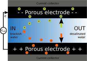 Adsorption of ions from the brackish water to desalinate it |
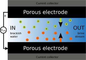 Desorption of ions from the brackish water to regenerate the electrodes |
Ion adsorption in Electrical Double Layers
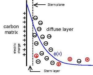
Any amount of charge should always be compensated by the same amount of counter-charge. For example, in an aqueous solution the concentration of the anions equals the concentration of cations. However, in the EDLs formed in the intraparticle pores, an excess of one type of ion over the other is possible, but it has to be compensated by electrical charge in the carbon matrix. In a first approximation, this EDL can be described using the Gouy-Chapman-Stern model, which distinguishes three different layers:[11][12][13]
- The porous carbon matrix, which contains the electrical charge in the carbon structure.
- A Stern layer is located between the carbon matrix and the diffuse layer. The Stern-layer is a dielectric layer, i.e. it separates two layers with charge, but it does not carry any charge itself.
- The diffuse layer, in which the ions compensate the electrical charge of the carbon matrix. The ions are diffusively distributed in this layer. The width of the diffuse layer can often be approximated using the Debye length, characterizing the distance for concentration of counter-ions to decrease by the factor 1/e. To illustrate this, the Debye length is about 3.1 nm at 20 °C and for a 10 mM NaCl solution. This implies that more than 95% of the electrical charge in the carbon matrix is compensated in a diffuse layer with a width of about 9 nm.
As the carbon matrix is charged, the charge has to be compensated by ionic charge in the diffuse layer. This can be done by either the adsorption of counterions, or the desorption of co-ions (ions with an equal charge sign as the one in the carbon matrix).
Besides the adsorption of ionic species due to the formation of EDLs in the intraparticle pores, ions can form a chemical bond with the surface area of the carbon particles as well. This is called specific adsorption, while the adsorption of ions in the EDLs is referred to as non-specific adsorption.[14]
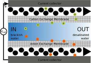
Membrane capacitive deionization
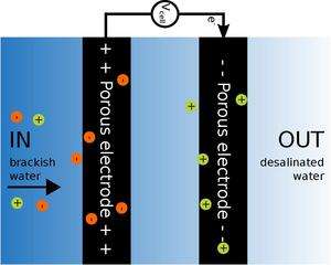
By inserting two ion exchange membranes, a modified form of CDI is obtained, namely Membrane Capacitive Deionization.[10] This modification improves the CDI cell in several ways:
- Co-ions do not leave the electrodes during the adsorption phase, as described above (see Ion adsorption in Electrical Double Layers for explanation). Instead, due to the inclusion of the ion exchange membranes, these co-ions will be kept in the interparticle pores of the electrodes, which enhances the salt adsorption efficiency.[15][16][17]
- Since these co-ions cannot leave the electrodes and because the electroneutrality condition applies for the interparticle pores, extra counter-ions must pass through the ion-exchange membranes, which gives rise to a higher salt adsorption as well.[15][16][17]
- Operating MCDI at constant current mode can produce freshwater with a stable effluent concentration (see constant voltage vs. constant current for more information).
- The required energy input of MCDI is lower than of CDI.[15][16][17][18]
| Capacitive deionization during the adsorption cycle |
 Membrane capacitive deionization during the adsorption cycle |
Constant voltage vs. constant current operation mode
A CDI cell can be operated in either the constant voltage or the constant current mode.
Constant voltage operation
During the adsorption phase of CDI using constant voltage operation, the salt effluent salt concentration decreases, but after a while, the effluent salt concentration increases again. This can be explained by the fact that the EDLs are uncharged at the beginning of an adsorption step, which results in a high potential difference (electrical driving force on the ions) over the two electrodes. When more ions are adsorbed in the EDLs, the EDL potential increases and the remaining potential difference between the electrodes, which drives the ion transport, decreases. Because of the decreasing ion removal rate, the effluent concentration increases again.[19][20]
Constant current operation
Since the ionic charge transported into the electrodes is equal to the applied electric current, applying a constant current allows a better control on the effluent salt concentration compared to the constant voltage operation mode. However, for a stable effluent salt concentration membranes should be incorporated in the cell design (MCDI), as the electric current does not only induce counter-ion adsorption, but co-ion depletion as well (see Membrane capacitive deionization vs. Capacitive deionization for an explanation).[19]
Cell geometries
Flow-by mode
The electrodes are placed in a stack with a thin spacer area in between, through which the water flows. This is by far the most commonly used mode of operation and electrodes, which are prepared in a similar fashion as for electrical double layer capacitors with a high carbon mass loading.
Flow-through mode
In this mode, the feed water flows straight through the electrodes, i.e. the water flows directly through the interparticle pores of the porous carbon electrodes. This approach has the benefit of ions directly migrating through these pores, hence mitigating transport limitations encountered in the flow-by mode.[21]
Flow-electrode capacitive deionization
This geometrical design is comparable to the flow-by mode with the inclusion of membranes in front of both electrodes, but instead of having solid electrodes, a carbon suspension (slurry) flows between the membranes and the current collector. A potential difference is applied between both channels of flowing carbon slurries, the so-called flow electrodes, and water is desalinated. Since the carbon slurries flow, the electrodes do not saturate and therefore this cell design can be used for the desalination of water with high salt concentrations as well (e.g. sea water, with salt concentrations of approximately 30 g/L). A discharging step is not necessary; the carbon slurries are, after leaving the cell, mixed together and the carbon slurry can be separated from a concentrated salt water stream.[22][23][24][25]
Capacitive deionization with wires
The freshwater stream can be made to flow continuously in a modified CDI configuration where the anode and cathode electrode pairs are not fixed in space, but made to move cyclically from one stream, in which the cell voltage is applied and salt is adsorbed, to another stream, where the cell voltage is reduced and salt is released.[26]
 Flow-through CDI cell during the adsorption cycle |
 Flow-electrode CDI cell during the adsorption cycle |
Electrode materials
For a high performance of the CDI cell, high quality electrode materials are of utmost importance. Carbon is the choice as porous electrode material. Regarding the structure of the carbon material, there are several considerations. As a high salt electrosorption capacity is important, the specific surface area and the pore size distribution of the carbon accessible for ions should be large. Furthermore, the used material should be stable and no chemical degradation of the electrode (degradation) should occur in the voltage window applied for CDI. The ions should be able to move fast through the pore network of the carbon and the conductivity of the carbon should be high. Lastly, the costs of the electrode materials are important to take into consideration.[27]
Nowadays, activated carbon (AC) is the commonly used material, as it is the most cost efficient option and it has a high specific surface area. It can be made from natural or synthetic sources. Other carbon materials used in CDI research are, for example, ordered mesoporous carbon, carbon aerogels, carbide-derived carbons, carbon nanotubes, graphene and carbon black.[3] Recent work argues that micropores, especially pores < 1.1 nm are the most effective for salt adsorption in CDI.[28]
However, activated carbon, at only US$ 4/kg for commodity carbon and US$ 15/kg for highly purified, specially selected supercapacitor carbon, remains much cheaper than the alternatives, which cost US$ 50/kg or more. Larger activated carbon electrodes are much cheaper than relatively small exotic carbon electrodes, and can remove just as much salt for a given current. The performance increase from novel carbons is insufficient to motivate their use at this point, especially since virtually all CDI applications under serious near-term consideration are stationary applications, where unit size is a relatively minor consideration.[2]
Energy requirements
Since the ionic content of water is demixed during a CDI adsorption cycle, the entropy of the system decreases and an external energy input is required. The theoretical energy input of CDI can be calculated as follows:
![{\displaystyle \Delta G=R*T*\Phi _{v,fresh}*(C_{feed}-C_{fresh})\left[{\frac {ln\alpha }{1-\alpha }}-{\frac {ln\beta }{1-\alpha }}\right]}](../I/m/40cb0a06f121f889fcc541a7858641f5ba26dab8.svg)
where R is the gas constant (8.314 J mol−1 K−1), T the temperature (K), Φv,fresh, the flow rate of the fresh water outflow (m3/s), Cfeed the concentration of ions in the feed water (mol/m3) and Cfresh the ion concentration in the fresh water outflow (mol/m3) of the CDI cell. α is defined Cfeed/Cfresh and β as Cfeed/Cconc, with Cconc the concentration of the ions in the concentrated outflow.
In practice, the energy requirements will be significantly higher than the theoretical energy input. Important energy requirements, which are not included in the theoretical energy requirements, are pumping, and losses in the CDI cell due to internal resistances. If MCDI and CDI are compared for the energy required per removed ion, MCDI has a lower energy requirement than CDI.[19]
Comparing CDI with reverse osmosis of water with salt concentrations lower than 20 mM, lab-scale research shows that the energy consumption in kWh per m3 freshwater produced can be lower for MCDI than for reverse osmosis.[3][29]
Large-scale CDI facilities
In 2007, a 10,000 tons per day full-scale CDI plant was built in China for improving the reclaimed water quality by ESTPURE.[30] This project enables the reduction of total dissolved solids from 1,000 mg/L to 250 mg/L and turbidity from 10 NTU to 1 NTU, a unit indicating the cloudiness of a fluid. The water recovery can reach 75%. Electrical energy consumption level is 1 kWh/m3, and the cost for water treatment is 0.22 US dollars/m3. Some other large-scale projects can be seen from the table below.
| Water source | Scale (m3/d) | Water recovery rate | Salt removal rate | Energy consumption (kWh/m3 produced water) | Reference |
|---|---|---|---|---|---|
| Municipal wastewater being treated by first and second order processes + circulating water | 10000 | 75% | 75% | 1.03 | [31] |
| Cooling water | 120000 | 75% | 85% of Cl− | 0.75 | [32] |
| Wastewater | 2400 | 75% | ≥50% | 1.33 | [30] |
References
- ↑ Suss, M.E.; Porada, S.; Sun, X.; Biesheuvel, P.M.; Yoon, J.; Presser, V. (2015). "Water desalination via capacitive deionization: what is it and what can we expect from it? [OPEN ACCESS]". Energy Environ. Sci. doi:10.1039/C5EE00519A.
- 1 2 Weinstein, Lawrence; Dash, R. (2013). "Capacitive Deionization: Challenges and Opportunities". Desalination & Water Reuse.
- 1 2 3 4 Porada, S.; Zhao, R.; Wal, A. van der; Presser, V.; Biesheuvel, P.M. (2013). "Review on the science and Technology of Water Desalination by Capacitive Deionization [OPEN ACCESS]". Progress in Materials Science. 58: 1388–1442. doi:10.1016/j.pmatsci.2013.03.005.
- 1 2 Anderson, M.A.; Cudero, A.L.; Palma, J. (2010). "Capacitive deionization as an electrochemical means of saving energy and delivering clean water. Comparing to present desalination practices: Will it compete?". Electrochimica Acta. 55 (12): 3845–3856. doi:10.1016/j.electacta.2010.02.012.
- ↑ "CDI & electrosorption". http://www.cdi-electrosorption.org. External link in
|website=(help); - ↑ Blair, J.W.; Murphy, G.W. (1960). "Electrochemical demineralization of Water with Porous Carbon Electrodes of Large Surface Area". 27. Washington D.C.: U.S. Dept. of the Interior.
- ↑ Reid, G.W. (1968). "Field operation of a 20 gallons per day pilot plant unit for electrochemical desalination of brackish water". 293. Washington D.C.: U.S. Dept. of the Interior.
- ↑ Johnson, A.M.; Venolia, A.W.; Wilbourne, R.G.; Newman, J.; Wong, C.M.; Gilliam, W.S. (1970). "The electrosorb processes for desalting water". 516. Washington D.C.: U.S. Dept. of the Interior.
- ↑ Farmer, J.C.; Fix, D.V.; Mack, G.W.; Pekala, R.W.; Poco, J.F. (1996). "Capacitive deionization of NaCl and NaNO3 solutions with carbon aerogel electrodes". Journal of the Electrochemical Society. 143 (1): 159–169. doi:10.1149/1.1836402.
- 1 2 Andelman (2004). "US6709560, Charge barrier flow-through capacitor".
- ↑ Kirby, B.J. "The diffuse structure of the electrical double layer".
- ↑ "Britannica - Electrical Double Layer".
- ↑ "TDA Research - Capacitive deionization".
- ↑ Ibach, H. (2006). Physics of Surfaces and Interfaces. Springer-Verlag.
- 1 2 3 Li, H.; Gao, Y.; Pan, L.; Zhang, Y.; Chen, Y.; Sun, Z. (2008). "Electrosorptive desalination by carbon nanotubes and nanofibres electrodes and ion-exchange membranes". Water Research. 42 (20): 4923–4928. doi:10.1016/j.watres.2008.09.026.
- 1 2 3 Kim, Y.; Choi, J. (2010). "Enhanced desalination efficiency in capacitive deionization with an ion-selective membrane". Separation and Purification Technology. 71 (1): 70–75. doi:10.1016/j.seppur.2009.10.026.
- 1 2 3 Zhao, R.; van Soestbergen, M.; Rijnaarts, H.H.M.; van der Wal, A.; Bazant, M.Z.; Biesheuvel, P.M. (2012). "Time-dependent ion selectivity in capacitive charging of porous electrodes". Journal of Colloid and Interface Science. 384: 38–44. doi:10.1016/j.jcis.2012.06.022.
- ↑ Lee, J.B.; Park, K.; Eum, H.; Lee, C. (2006). "Desalination of a thermal power plant wastewater by membrane capacitive deionization". Desalination. 196 (1): 125–134. doi:10.1016/j.desal.2006.01.011.
- 1 2 3 Zhao, R.; Biesheuvel, P.M.; van der Wal, A. (2012). "Energy consumption and constant current operation in membrane capacitive deionization". Energy & Environmental Science. 5 (11): 9520–9527. doi:10.1039/c2ee21737f.
- ↑ Kim, T.; Dykstra, J.E.; Porada, S; van der Wal, A.; Yoon, J.; Biesheuvel, P.M. (2014). "Enhanced energy and charge efficiencies by increasing the discharge voltage in capacitive deionization". J. Colloid Interface Science. 446: 317–326. doi:10.1016/j.jcis.2014.08.041.
- ↑ Suss, M.E.; Baumann, T.F.; Bourcier, W.L.; Spadaccini, C.M.; Rose, K.L.; Santiago, J.G.; Stadermann, M. (2012). "Capacitive desalination with flow-through electrodes" Check
|url=value (help). Energy & Environmental Science. 5 (11): 9511–9519. doi:10.1039/c2ee21498a. - ↑ Jeon, S.; Park, H.; Jeo, Y.; Yang, S.; Cho, C.H.; Han, M.H.; Kim, D.K. (2013). "Desalination via a new membrane capacitive deionization process utilizing flow-electrodes". Energy & Environmental Science. 6 (5): 1471–1475. doi:10.1039/c3ee24443a.
- ↑ Hatzell, Kelsey; Iwama, Etsuro; Ferris, Anais; Daffos, Barbara; Urita, Koki; Tzedakis, Theodore; Chauvet, Fabien; Taberna, Pierre-Louis; Gogotsi, Yury; Simon, Patrice (2014). "Capacitive deionization concept based on suspension electrodes without ion exchange membranes". Electrochemical Communications. 43 (43): 18–21. doi:10.1016/j.elecom.2014.03.003.
- ↑ Porada, S; Weingarth, D; Hamelers, H.V.M; Bryjak, M; Presser, V; Biesheuvel, P.M. (2014). "Carbon flow electrodes for continuous operation of capacitive deionization and capacitive mixing energy generation". Journal of Materials Chemistry A. 2: 9313–9321. doi:10.1039/c4ta01783h.
- ↑ Hatzell, Kelsey B.; Hatzell, Marta C.; Cook, Kevin M.; Boota, Muhammad; Housel, Gabrielle; McBride, Alex; Gogotsi, Yury (2015). "Effect of Oxidation of Carbon Material on Suspension Electrodes for Flow Electrode Capacitive Deionization". Environmental Science and Technology. 49 (5): 3040–3047. doi:10.1021/es5055989.
- ↑ Porada, S.; Sales, B. B.; Hamelers, H. V. M.; Biesheuvel, P. M. (2012). "Water Desalination with Wires". The Journal of Physical Chemistry Letters. 3 (12): 1613–1618. doi:10.1021/jz3005514.
- ↑ Oren, Y. (2008). "Capacitive deionization (CDI) for desalination and water treatment — past, present and future (a review)". Desalination. 228 (1): 10–29. doi:10.1016/j.desal.2007.08.005.
- ↑ Porada, S.; Borchardt, L.; Oschatz, M.; Bryjak, M.; Atchison, J. S.; Keesman, K. J.; Kaskel, S.; Biesheuvel, P. M.; Presser, V. (2013). "Direct prediction of the desalination performance of porous carbon electrodes for capacitive deionisation [OPEN ACCESS]". Energy & Environmental Science. 6 (12): 3700. doi:10.1039/c3ee42209g.
- ↑ Zhao, R.; Porada, S.; Biesheuvel, P.M.; van der Wal, A. (December 2013). "Energy consumption in membrane capacitive deionization for different water recoveries and flow rates, and comparison with reverse osmosis". Desalination. 330: 35–41. doi:10.1016/j.desal.2013.08.017.
- 1 2 ESPURE. "A chemical wastewater reuse and quality promotion project in Shanxi". Archived from the original on 2013-12-03.
- ↑ ESTPURE. "Inner Mongolia power group water recycling project". Archived from the original on 2013-12-03.
- ↑ ESTPURE. "A water reclaimed water plant upgrade project in Ningbo, Zhejiang". Archived from the original on 2013-12-02.