Numerical control
Computer Numeric Control (CNC[1]) is the automation of machine tools that are operated by precisely programmed commands encoded on a storage medium (computer command module, usually located on the device) as opposed to controlled manually by hand wheels or levers, or mechanically automated by cams alone. Most NC today is computer (or computerized) numerical control (CNC),[2] in which computers play an integral part of the control.
In modern CNC systems, end-to-end component design is highly automated using computer-aided design (CAD) and computer-aided manufacturing (CAM) programs. The programs produce a computer file that is interpreted to extract the commands needed to operate a particular machine by use of a post processor, and then loaded into the CNC machines for production. Since any particular component might require the use of a number of different tools – drills, saws, etc. – modern machines often combine multiple tools into a single "cell". In other installations, a number of different machines are used with an external controller and human or robotic operators that move the component from machine to machine. In either case, the series of steps needed to produce any part is highly automated and produces a part that closely matches the original CAD design.
History
The first NC machines were built in the 1940s and 1950s, based on existing tools that were modified with motors that moved the controls to follow points fed into the system on punched tape. These early servomechanisms were rapidly augmented with analog and digital computers, creating the modern CNC machine tools that have revolutionized the machining processes.
Description
Motion is controlled along multiple axes, normally at least two (X and Y),[3] and a tool spindle that moves in the Z (depth). The position of the tool is driven by direct-drive stepper motor or servo motors in order to provide highly accurate movements, or in older designs, motors through a series of step down gears. Open-loop control works as long as the forces are kept small enough and speeds are not too great. On commercial metalworking machines, closed loop controls are standard and required in order to provide the accuracy, speed, and repeatability demanded.
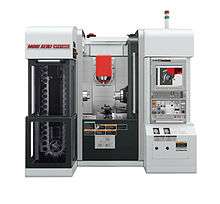
As the controller hardware evolved, the mills themselves also evolved. One change has been to enclose the entire mechanism in a large box as a safety measure, often with additional safety interlocks to ensure the operator is far enough from the working piece for safe operation. Most new CNC systems built today are 100% electronically controlled.
CNC-like systems are now used for any process that can be described as a series of movements and operations. These include laser cutting, welding, friction stir welding, ultrasonic welding, flame and plasma cutting, bending, spinning, hole-punching, pinning, gluing, fabric cutting, sewing, tape and fiber placement, routing, picking and placing, and sawing.
Examples of CNC machines
Mills
CNC mills use computer controls to cut different materials. They are able to translate programs consisting of specific numbers and letters to move the spindle (or workpiece) to various locations and depths. Many use G-code, which is a standardized programming language that many CNC machines understand, while others use proprietary languages created by their manufacturers. These proprietary languages, while often simpler than G-code, are not transferable to other machines. CNC mills have many functions including face milling, shoulder milling, tapping, drilling and some even offer turning. Standard linear CNC mills are limited to 3 axis (X, Y, and Z), but others may also have one or more rotational axes. Today, CNC mills can have 4 to 6 axes.
Lathes

Lathes are machines that cut workpieces while they are rotated. CNC lathes are able to make fast, precision cuts, generally using indexable tools and drills. They are particularly effective for complicated programs designed to make parts that would be infeasible to make on manual lathes. CNC lathes have similar control specifications to CNC mills and can often read G-code as well as the manufacturer's proprietary programming language. CNC lathes generally have two axes (X and Z), but newer models have more axes, allowing for more advanced jobs to be machined.
Plasma cutters

Plasma cutting involves cutting a material using a plasma torch. It is commonly used to cut steel and other metals, but can be used on a variety of materials. In this process, gas (such as compressed air) is blown at high speed out of a nozzle; at the same time an electrical arc is formed through that gas from the nozzle to the surface being cut, turning some of that gas to plasma. The plasma is sufficiently hot to melt the material being cut and moves sufficiently fast to blow molten metal away from the cut.
Electric discharge machining
Electric discharge machining (EDM), sometimes colloquially also referred to as spark machining, spark eroding, burning, die sinking, or wire erosion, is a manufacturing process in which a desired shape is obtained using electrical discharges (sparks). Material is removed from the workpiece by a series of rapidly recurring current discharges between two electrodes, separated by a dielectric fluid and subject to an electric voltage. One of the electrodes is called the tool electrode, or simply the "tool" or "electrode," while the other is called the workpiece electrode, or "workpiece."
When the distance between the two electrodes is reduced, the intensity of the electric field in the space between the electrodes becomes greater than the strength of the dielectric (at the nearest point(s)), which electrically break down, allowing current to flow between the two electrodes. This phenomenon is the same as the breakdown of a capacitor. As a result, material is removed from both the electrodes. Once the current flow stops (or it is stopped – depending on the type of generator), new liquid dielectric is usually conveyed into the inter-electrode volume, enabling the solid particles (debris) to be carried away and the insulating properties of the dielectric to be restored. Adding new liquid dielectric in the inter-electrode volume is commonly referred to as flushing. Also, after a current flow, a difference of potential between the two electrodes is restored to what it was before the breakdown, so that a new liquid dielectric breakdown can occur.
Wire EDM
Also known as wire cutting EDM, wire burning EDM, or traveling wire EDM, this process uses spark erosion to machine or remove material with a traveling wire electrode from any electrically conductive material. The wire electrode usually consists of brass or zinc-coated brass material.
Sinker EDM
Sinker EDM, also called cavity type EDM or volume EDM, consists of an electrode and workpiece submerged in an insulating liquid—often oil but sometimes other dielectric fluids. The electrode and workpiece are connected to a suitable power supply, which generates an electrical potential between the two parts. As the electrode approaches the workpiece, dielectric breakdown occurs in the fluid forming a plasma channel) and a small spark jumps.
Water jet cutters
A water jet cutter, also known as a waterjet, is a tool capable of slicing into metal or other materials (such as granite) by using a jet of water at high velocity and pressure, or a mixture of water and an abrasive substance, such as sand. It is often used during fabrication or manufacture of parts for machinery and other devices. Waterjet is the preferred method when the materials being cut are sensitive to the high temperatures generated by other methods. It has found applications in a diverse number of industries from mining to aerospace where it is used for operations such as cutting, shaping, carving, and reaming.
Other CNC tools
Many other tools have CNC variants, including:
- Drills
- EDMs
- Embroidery machines
- Lathes
- Milling machines
- Canned cycle
- Wood routers
- Sheet metal works (Turret punch)
- Wire bending machines
- Hot-wire foam cutters
- Plasma cutters
- Water jet cutters
- Laser cutting
- Oxy-fuel
- Surface grinders
- Cylindrical grinders
- 3D Printing
- Induction hardening machines
- Submerged welding
- Knife cutting
- Glass cutting
Tool / machine crashing
In CNC, a "crash" occurs when the machine moves in such a way that is harmful to the machine, tools, or parts being machined, sometimes resulting in bending or breakage of cutting tools, accessory clamps, vises, and fixtures, or causing damage to the machine itself by bending guide rails, breaking drive screws, or causing structural components to crack or deform under strain. A mild crash may not damage the machine or tools, but may damage the part being machined so that it must be scrapped.
Many CNC tools have no inherent sense of the absolute position of the table or tools when turned on. They must be manually "homed" or "zeroed" to have any reference to work from, and these limits are just for figuring out the location of the part to work with it, and aren't really any sort of hard motion limit on the mechanism. It is often possible to drive the machine outside the physical bounds of its drive mechanism, resulting in a collision with itself or damage to the drive mechanism. Many machines implement control parameters limiting axis motion past a certain limit in addition to physical limit switches. However, these parameters can often be changed by the operator.
Many CNC tools also don't know anything about their working environment. Machines may have load sensing systems on spindle and axis drives, but some do not. They blindly follow the machining code provided and it is up to an operator to detect if a crash is either occurring or about to occur, and for the operator to manually abort the cutting process. Machines equipped with load sensors can stop axis or spindle movement in response to an overload condition, but this does not prevent a crash from occurring. It may only limit the damage resulting from the crash. Some crashes may not ever overload any axis or spindle drives.
If the drive system is weaker than the machine structural integrity, then the drive system simply pushes against the obstruction and the drive motors "slip in place". The machine tool may not detect the collision or the slipping, so for example the tool should now be at 210 mm on the X axis, but is, in fact, at 32mm where it hit the obstruction and kept slipping. All of the next tool motions will be off by −178mm on the X axis, and all future motions are now invalid, which may result in further collisions with clamps, vises, or the machine itself. This is common in open loop stepper systems, but is not possible in closed loop systems unless mechanical slippage between the motor and drive mechanism has occurred. Instead, in a closed loop system, the machine will continue to attempt to move against the load until either the drive motor goes into an overcurrent condition or a servo following error alarm is generated.
Collision detection and avoidance is possible, through the use of absolute position sensors (optical encoder strips or disks) to verify that motion occurred, or torque sensors or power-draw sensors on the drive system to detect abnormal strain when the machine should just be moving and not cutting, but these are not a common component of most hobby CNC tools.
Instead, most hobby CNC tools simply rely on the assumed accuracy of stepper motors that rotate a specific number of degrees in response to magnetic field changes. It is often assumed the stepper is perfectly accurate and never missteps, so tool position monitoring simply involves counting the number of pulses sent to the stepper over time. An alternate means of stepper position monitoring is usually not available, so crash or slip detection is not possible.
Commercial CNC metalworking machines use closed loop feedback controls for axis movement. In a closed loop system, the control is aware of the actual position of the axis at all times. With proper control programming, this will reduce the possibility of a crash, but it is still up to the operator and programmer to ensure that the machine is operated in a safe manner. However, during the 2000s and 2010s, the software for machining simulation has been maturing rapidly, and it is no longer uncommon for the entire machine tool envelope (including all axes, spindles, chucks, turrets, tool holders, tailstocks, fixtures, clamps, and stock) to be modeled accurately with 3D solid models, which allows the simulation software to predict fairly accurately whether a cycle will involve a crash. Although such simulation is not new, its accuracy and market penetration are changing considerably because of computing advancements.[4]
Numerical precision and equipment backlash
Within the numerical systems of CNC programming it is possible for the code generator to assume that the controlled mechanism is always perfectly accurate, or that precision tolerances are identical for all cutting or movement directions. This is not always a true condition of CNC tools. CNC tools with a large amount of mechanical backlash can still be highly precise if the drive or cutting mechanism is only driven so as to apply cutting force from one direction, and all driving systems are pressed tightly together in that one cutting direction. However a CNC device with high backlash and a dull cutting tool can lead to cutter chatter and possible workpiece gouging. Backlash also affects precision of some operations involving axis movement reversals during cutting, such as the milling of a circle, where axis motion is sinusoidal. However, this can be compensated for if the amount of backlash is precisely known by linear encoders or manual measurement.
The high backlash mechanism itself is not necessarily relied on to be repeatedly precise for the cutting process, but some other reference object or precision surface may be used to zero the mechanism, by tightly applying pressure against the reference and setting that as the zero reference for all following CNC-encoded motions. This is similar to the manual machine tool method of clamping a micrometer onto a reference beam and adjusting the Vernier dial to zero using that object as the reference.
Positioning control system in NC
In NC system the position of the tool is defined by the part program of instruction that store by the machine control unit(MCU). Two type of positioning control system are used in the NC system:
- Open loop control system
- closed loop control system[5]
open loop control system
This system operates without verifying that actual position achieved by the worktable. After the executing the program by MCU, it does not use any feedback so it known as the open loop system.[6]
closed loop control system
A closed loop control system uses feedback measurements to confirm that the final position of the worktable is the location specified in the program.[6]
comparison of some parameter of the open loop and closed loop system
| S. No. | Open loop control system | closed loop control system |
| 1. | Less expensive | More expensive |
| 2. | Not use any feedback mechanism | Use feedback mechanism |
| 3. | Any type of motion control system | Mostly used for continuous path system |
| 4. | Generally used stepper motor | Servo motor |
| 5. | Less accurate at high speed | Accuracy is high compared to open loop system |
See also
- Binary Cutter Location
- Computer-aided technologies
- Coordinate-measuring machine (CMM)
- Direct numerical control (DNC)
- Design for Manufacturability for CNC machining
- Domotics
- Gerber format
- Multiaxis machining
- EIA RS-274
- EIA RS-494
- G-code
- Part program
- Robotics
- Wireless DNC
- Automatic Tool Changer
References
- ↑ "About CNC Machining". www.thomasnet.com. Retrieved 2016-06-04.
- ↑ "Computerized Numerical Control". www.sheltonstate.edu. Shelton State Community College. Retrieved March 24, 2015.
- ↑ Mike Lynch, "Key CNC Concept #1—The Fundamentals Of CNC", Modern Machine Shop, 4 January 1997. Accessed 11 February 2015
- ↑ Zelinski, Peter (2014-03-14), "New users are adopting simulation software", Modern Machine Shop.
- 1 2 P. GROOVER, MIKELL (2015). AUTOMATION, PRODUCTION SYSTEM, AND COMPUTER- INTEGRAE MANUFACTURING. india: PEARSON. pp. 166–167. ISBN 9789332549814.
- 1 2 patel, sushik (4 May 2016). "open loop system".
Further reading
- Brittain, James (1992), Alexanderson: Pioneer in American Electrical Engineering, Johns Hopkins University Press, ISBN 0-8018-4228-X.
- Holland, Max (1989), When the Machine Stopped: A Cautionary Tale from Industrial America, Boston: Harvard Business School Press, ISBN 978-0-87584-208-0, OCLC 246343673.
- Noble, David F. (1984), Forces of Production: A Social History of Industrial Automation, New York, New York, USA: Knopf, ISBN 978-0-394-51262-4, LCCN 83048867.
- Reintjes, J. Francis (1991), Numerical Control: Making a New Technology, Oxford University Press, ISBN 978-0-19-506772-9.
- Weisberg, David, The Engineering Design Revolution, archived from the original (PDF) on 9 March 2010.
- Wildes, Karl L.; Lindgren, Nilo A. (1985), A Century of Electrical Engineering and Computer Science at MIT, MIT Press, ISBN 0-262-23119-0.
- Herrin, Golden E. "Industry Honors The Inventor Of NC", Modern Machine Shop, 12 January 1998.
- Siegel, Arnold. "Automatic Programming of Numerically Controlled Machine Tools", Control Engineering, Volume 3 Issue 10 (October 1956), pp. 65–70.
- Smid, Peter (2008), CNC Programming Handbook (3rd ed.), New York: Industrial Press, ISBN 9780831133474, LCCN 2007045901.
- Christopher jun Pagarigan (Vini) Edmnton Alberta Canada. CNC Infomatic, Automotive Design & Production.
- Nguyen, Van Khai; Stark, John (2009), STEP-compliant CNC Systems, Present and Future Directions, Springer, doi:10.1007/978-1-84882-739-4_10
- What is a CNC machine? (2016). Retrieved July 19, 2016, from CNC Machine Training
External links
 Media related to Computer numerical control at Wikimedia Commons
| Main articles |  | |
|---|---|---|
| Types | ||
| Classifications | ||
| Locomotion | ||
| Research | ||
| Related | ||
| ||