Box girder


A box or tubular girder is a girder that forms an enclosed tube with multiple walls, rather than an I or H-beam. Originally constructed of riveted wrought iron, they are now found in rolled or welded steel, aluminium extrusions or prestressed concrete.
Compared to an I-beam, the advantage of a box girder is that it better resists torsion. Having multiple vertical webs, it can also carry more load than an I-beam of equal height (although it will use more material than a taller I-beam of equivalent capacity).
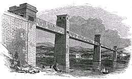
The distinction in naming between a box girder and a tubular girder is imprecise. Generally the term box girder is used, especially if it is rectangular in section. Where the girder carries its "content" inside the box, such as the Britannia Bridge, it is termed a tubular girder. Tubular girder is also used if the girder is round or oval in cross-section, such as the Royal Albert Bridge.
Where a large box girder contains more than two walls, i.e. with multiple boxes, it is referred to as a cellular girder.
Development of the box girder
The theoretical basis of the box girder was largely the work of the engineer Sir William Fairbairn, with the aid of the mathematician Eaton Hodgkinson, around 1830. They sought an optimal design for the most efficient design of beam in the new material of riveted wrought iron plates.
Cellular construction
Most girders are statically loaded such that one web is in compression, the other in tension. Fairbairn's original cranes used a cellular construction for the compression face for their jib, so as to resist buckling. This jib was curved, tapered and formed of riveted wrought iron plates. Three cells were formed inside the concave (lower) face of this girder, again of riveted plates.[1]
Where a tubular girder is used as a bridge span (i.e. loaded in the centre rather than at one end, like a crane) the compressive force is in the top web of the girder and so the cells are placed at the top. Dynamic forces (moving loads, wind) may also require both faces to be cellular, as may be seen in the Britannia Bridge section.
In some ways this isn't a "cellular girder" as such (compared to a spaceframe or geodesic construction) as the cells don't share loads from the entire girder, but merely act to stiffen one plate in isolation. Design of such complex integrated structures requires mathematical modelling techniques in advance of Fairbairn's day.
Box girders in bridges
Fairbairn's theoretical girder appeared at just the right time for the increasing demand for long railway bridges. Robert Stephenson engaged both him and Hodgkinson as consultants to assist with his Britannia and Conwy bridges, both of which contained the railway track within a large tubular girder. Shortly afterwards Brunel also chose to use a pair of small diameter round girders as part of a larger truss at Chepstow. The Coronado Bay Bridge has the tallest box girder.
Safety concerns over box girder bridges
In the early 1970s, a number of box girder bridges collapsed during construction: the Cleddau Bridge in Wales, West Gate Bridge in Australia and the Koblenz Bridge in Germany. These led to extensive studies of the safety of box girders and serious concern over their continued use. This was also an early use of computer modeling and a spur to the development of finite element analysis in civil engineering.
See also
Bridges
- Tubular bridges
- Box girder bridges
- Cleddau Bridge
- West Gate Bridge
- Koblenz Bridge
- Gateway Bridge, Brisbane, Queensland, Australia
References
- ↑ Fairbairn, William (1856). Useful Information for Engineers. London: Longmans. p. 283.