Bevel gear
Bevel gears are gears where the axes of the two shafts intersect and the tooth-bearing faces of the gears themselves are conically shaped. Bevel gears are most often mounted on shafts that are 90 degrees apart, but can be designed to work at other angles as well.[1] The pitch surface of bevel gears is a cone.


Introduction
Two important concepts in gearing are pitch surface and pitch angle. The pitch surface of a gear is the imaginary toothless surface that you would have by averaging out the peaks and valleys of the individual teeth. The pitch surface of an ordinary gear is the shape of a cylinder. The pitch angle of a gear is the angle between the face of the pitch surface and the axis.
The most familiar kinds of bevel gears have pitch angles of less than 90 degrees and therefore are cone-shaped. This type of bevel gear is called external because the gear teeth point outward. The pitch surfaces of meshed external bevel gears are coaxial with the gear shafts; the apexes of the two surfaces are at the point of intersection of the shaft axes.
Bevel gears that have pitch angles of greater than ninety degrees have teeth that point inward and are called internal bevel gears.
Bevel gears that have pitch angles of exactly 90 degrees have teeth that point outward parallel with the axis and resemble the points on a crown. That's why this type of bevel gear is called a crown gear.
Miter gears are mating bevel gears with equal numbers of teeth and with axes at right angles.
Skew bevel gears are those for which the corresponding crown gear has teeth that are straight and oblique.
Types
Bevel gears are classified in different types according to geometry:
- Straight bevel gears have conical pitch surface and teeth are straight and tapering towards apex.
- Spiral bevel gears have curved teeth at an angle allowing tooth contact to be gradual and smooth.
- Zerol bevel gears are very similar to a bevel gear only exception is the teeth are curved: the ends of each tooth are coplanar with the axis, but the middle of each tooth is swept circumferentially around the gear. Zerol bevel gears can be thought of as spiral bevel gears, which also have curved teeth, but with a spiral angle of zero, so the ends of the teeth align with the axis.
- Hypoid bevel gears are similar to spiral bevel but the pitch surfaces are hyperbolic and not conical. Pinion can be offset above, or below,the gear centre, thus allowing larger pinion diameter, and longer life and smoother mesh, with additional ratios e.g., 6:1, 8:1, 10:1. In a limiting case of making the "bevel" surface parallel with the axis of rotation, this configuration resembles a worm drive. Hypoid gears were widely used in automobile rear axles.

Mitre Gears

Mitre gears are a type of bevel gears that have equal numbers of teeth. The shafts are positioned at right angles from each other, and the gears have matching pitch surfaces and angles, with a conically shaped pitch surface.[2]
Mitre gears are useful for transmitting rotational motion at a 90 degree angle with a 1:1 ratio.
Geometry of a Bevel Gear

The cylindrical gear tooth profile corresponds to an involute, whereas the bevel gear tooth profile is an octoid. All traditional bevel gear generators (such as Gleason, Klingelnberg, Heidenreich & Harbeck, WMW Modul) manufacture bevel gears with an octoidal tooth profile. IMPORTANT: For 5-axis milled bevel gear sets it is important to choose the same calculation / layout like the conventional manufacturing method. Simplified calculated bevel gears on the basis of an equivalent cylindrical gear in normal section with an involute tooth form show a deviant tooth form with reduced tooth strength by 10-28% without offset and 45% with offset [Diss. Hünecke, TU Dresden]. Furthermore those "involute bevel gear sets" causes more noise.
List of Drawing Symbols
- Np - Number of teeth on pinion
- Ng - Number of teeth on given gear
- Dg - Pitch diameter of given gear
- Dp - Pitch diameter of given pinion
- F - Face width (length of single tooth)
- γ - Pinion pitch angle (radians)
- Γ - Gear pitch angle (radians)
- Ao - Cone distance (distance from pitch circle to intersection of shaft axes)
- rb - Back-cone radius
- P - Diametrical pitch (teeth per inch of pitch diameter (N/D))
- p - Circular pitch (inches of circumference per tooth (Π/P))
The tooth shape for bevel gears is determined by scaling spur gear tooth shapes along the face width. The further from the intersection of the gear and pinion axes, the bigger the tooth cross sections are. If the tooth face were to extend all the way to the axes intersection, the teeth would approach infinitesimal size there. The tooth cross-section at the largest part of the tooth is identical to the tooth cross-section of a tooth from a spur gear with Pitch Diameter of 2* rb, or twice the Back-Cone Radius, and with an imaginary number of teeth (N’) equal to times the Back-Cone Radius (rb) divided by the Circular Pitch of the bevel gear (p). This method of obtaining the dimensions and shape of the largest tooth profile is known as the “Tredgold” tooth-shape approximation. Refer to the profiles shown near the Back-cone radius dimension in the drawing above.[3]

Mean radius:
Hp=Tx n/63000 → T = Hp x 63000/n
T = Rm x Wt → Wt = Hp x 63000/ n x Rm
Teeth
There are two issues regarding tooth shape. One is the cross-sectional profile of the individual tooth. The other is the line or curve on which the tooth is set on the face of the gear: in other words the line or curve along which the cross-sectional profile is projected to form the actual three-dimensional shape of the tooth. The primary effect of both the cross-sectional profile and the tooth line or curve is on the smoothness of operation of the gears. Some result in a smoother gear action than others.
Tooth line
The teeth on bevel gears can be straight, spiral or "zerol".
Straight tooth lines
In straight bevel gears the teeth are straight and parallel to the generators of the cone. This is the simplest form of bevel gear. It resembles a spur gear, only conical rather than cylindrical. The gears in the floodgate picture are straight bevel gears. In straight bevel gear sets, when each tooth engages it impacts the corresponding tooth and simply curving the gear teeth can solve the problem.
Spiral tooth lines
Spiral bevel gears have their teeth formed along spiral lines. They are somewhat analogous to cylindrical type helical gears in that the teeth are angled; however, with spiral gears the teeth are also curved.
The advantage of the spiral tooth over the straight tooth is that they engage more gradually. The contact between the teeth starts at one end of the gear and then spreads across the whole tooth. This results in a less abrupt transfer of force when a new pair of teeth come into play. With straight bevel gears, the abrupt tooth engagement causes noise, especially at high speeds, and impact stress on the teeth which makes them unable to take heavy loads at high speeds without breaking. For these reasons straight bevel gears are generally limited to use at linear speeds less than 1000 feet/min; or, for small gears, under 1000 r.p.m.[4]
Zerol tooth lines
Zerol bevel gears are an intermediate type between straight and spiral bevel gears. Their teeth are curved, but not angled. Zerol bevel gears are designed with the intent of duplicating the characteristics of a straight bevel gear but they are produced using a spiral bevel cutting process.
Manufacturing Bevel Gear
Materials used in gear manufacturing process
The various materials used for gears include a wide variety of cast irons, non ferrous material and non – metallic materials. The selection of the gear material depends upon:
- Type of service
- Peripheral speed
- Degree of accuracy required
- Method of manufacture
- Required dimensions and weight of the drive
- Allowable stress
- Shock resistance
- Wear resistance.
Some materials chosen include:
- Cast iron, which is popular due to its good wearing properties, excellent machinability and ease of producing complicated shapes by the casting method. It is suitable where large gears of complicated shapes are needed.
- Steel, which is sufficiently strong & highly resistant to wear by abrasion.
- Cast steel, which is used where stress on the gear is high and it is difficult to fabricate the gears.
- Plain carbon steels, which find application for industrial gears where high toughness combined with high strength.
- Alloy steels, which are used where high tooth strength and low tooth wear are required.
- Aluminum, which is used where low inertia of rotating mass is desired.
- Gears made of non–metallic materials give noiseless operation at high peripheral speeds.
Bevel Gearing
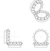
Two bevel gears in mesh is known as bevel gearing. In bevel gearing, the pitch cone angles of the pinion and gear are to be determined from the shaft angle, i.e., the angle between the intersecting shafts. Figure shows views of a bevel gearing.
Applications
The bevel gear has many diverse applications such as locomotives, marine applications, automobiles, printing presses, cooling towers, power plants, steel plants, railway track inspection machines, etc.
For examples, see the following articles on:
- Bevel gears are used in differential drives, which can transmit power to two axles spinning at different speeds, such as those on a cornering automobile.
- Bevel gears are used as the main mechanism for a hand drill. As the handle of the drill is turned in a vertical direction, the bevel gears change the rotation of the chuck to a horizontal rotation. The bevel gears in a hand drill have the added advantage of increasing the speed of rotation of the chuck and this makes it possible to drill a range of materials.
- The gears in a bevel gear planer permit minor adjustment during assembly and allow for some displacement due to deflection under operating loads without concentrating the load on the end of the tooth.
- Spiral bevel gears are important components on rotorcraft drive systems. These components are required to operate at high speeds, high loads, and for a large number of load cycles. In this application, spiral bevel gears are used to redirect the shaft from the horizontal gas turbine engine to the vertical rotor.

Advantages
- This gear makes it possible to change the operating angle.
- Differing of the number of teeth (effectively diameter) on each wheel allows mechanical advantage to be changed. By increasing or decreasing the ratio of teeth between the drive and driven wheels one may change the ratio of rotations between the two, meaning that the rotational drive and torque of the second wheel can be changed in relation to the first, with speed increasing and torque decreasing, or speed decreasing and torque increasing.
Disadvantages
- One wheel of such gear is designed to work with its complementary wheel and no other.
- Must be precisely mounted.
- The shafts' bearings must be capable of supporting significant forces.
See also
| Wikimedia Commons has media related to Bevel gears. |
References
- ↑ Fred Herbert Colvin; Frank Arthur Stanley (1914). American Machinists' Handbook and Dictionary of Shop Terms: A Reference Book of Machine Shop and Drawing Room Data, Methods and Definitions. McGraw-Hill book Company, Incorporated. p. 121. Retrieved 14 August 2014.
- ↑ "What is the definition of miter gear?". toolingu.com. Retrieved 2014-03-11.
- ↑ "Bevel Gear Geometry" (PDF). myoops.org. Retrieved 15 August 2014.
- ↑ Doughty and Vallance, Design of Machine Members.