Barring engine
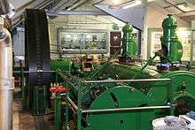

Note the drive by internal gear teeth.
A barring engine is a small engine, usually a steam engine, that forms part of the installation of a large stationary steam engine. It is used to turn the main engine to a favourable position from which it can be started. If the main engine has stopped close to its dead centre it is unable to restart itself.[1]
Barring may also be done to turn the engine over slowly (unloaded) for maintenance, or to prevent belt drives being left too long in one position and taking a "set".
Development
The first barring engines or barring gear were manual. At their simplest, they were a hefty engineer with a crowbar (hence the term "barring"). The engine's flywheel could be provided with a series of holes or teeth and a roller fulcrum set into the frame at a convenient place. Later manual barring engines had geared drives and a crank handle. With suitable reduction gears, even very large engines could be barred by hand. This only needed to be done once a day and was not a hurried operation, so speed was not crucial.
Where a steam barring engine was used, this was a small twin-cylinder engine (to avoid its own dead centre problems) with a reduction gear of high ratio, usually involving a worm gear. Final drive was by a pinion gear engaging temporarily with the teeth or barring holes cut into the rim of the main flywheel. The drive pinion was arranged on a swinging link so that it was thrown out-of-mesh automatically, once the main engine started to rotate at full speed. As the ratio was perhaps 1000:1 and the main engine ran at 60 rpm, this would otherwise have been a disastrous overspeed.[1] Some engines instead used a final pinion on a helical spline, similar to that later used for the starters of internal combustion engines: once the main engine started, the pinion would be thrown out of engagement axially along this spline as the flywheel over-speeded the pinion relative to the shaft.[2]
As mill engines became more powerful, from around 1870 there was a shift from single belt drives to multiple rope drives.[3] The barring engine needed to turn these rope drives over as well (although they were disconnected from the machinery at the remote end) and a simple manual gear was no longer sufficient. Around 1881–1883 there was a shift to the use of steam-powered barring engines.[3]
Each mill engine manufacturer had their own style of barring engine.[1] Unlike other smaller components, such as feed water pumps, they were rarely bought-in from other makers. Usually, though, a standard design was used for all sizes of engine, with additional gearing if it was required to bar a particularly large engine.
Preservation today
As barring engines are small, numerous examples have survived into preservation. The Bolton Steam Museum has a collection of several.[1]
See also
References
- 1 2 3 4 "Barring Engines". Northern Mill Engine Society.
- ↑ "Barring Engine". The Engineer: 500. 25 June 1886.
- 1 2 Hills, Richard L. (1989). Power from Steam. Cambridge University Press. pp. 211–212. ISBN 0-521-45834-X.
External links
| Wikimedia Commons has media related to Barring engines. |
- Video of barring engine at work – starting a large rotative beam engine at Crossness Pumping Station, London